Search
Close this search box.

KRRASS CNC Press Brake installation

KRRASS CNC Press Brake installation

The tonnage of the press brake is gradually increasing with the continuous improvement of technology, followed by the increase in the size of the machine itself. This brings a lot of problems for logistics and transportation. In order to solve the problem of large size of the press brake, we usually need to disassemble the machine for transportation during transportation.

However, after the user receives the machine, he needs to reassemble the machine for use. Today, we will teach users how to assemble a brand new press brake:

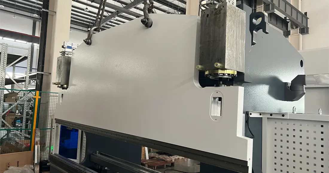
1. When we receive the press brake, we must first lift the slider of the press brake, as shown in Figure 1:

Lift the slider by means of the lifting rings above the slider
Figure 1: Lift the slider by means of the lifting rings above the slider

2. Lock the nuts on the left and right sides of the slider, as shown in Figure 2-1 and 2-2:

Lock the nuts on the left and right sides of the slider
Figure 2-1: Lock the nuts on the left and right sides of the slider
Lock the nuts on the left and right sides of the slider
Figure 2-2: Lock the nuts on the left and right sides of the slider

3. Install the grating scales on both sides of the fuselage in sequence, as shown in Figure 3-1 and 3-2: (If the machine has not been disassembled, this step can be skipped, depending on the machine model)

Install the grating ruler bracket through the screw hole
Figure 3-1: Install the grating ruler bracket through the screw hole
The effect of the installation of the grating ruler bracket
Figure 3-2: The effect of the installation of the grating ruler bracket

4. Install the proportional valves above the Y1 and Y2 axes in sequence, as shown in Figure 4-1 and 4-2. When installing, ensure that the position where the proportional valve is installed above the oil cylinder is clean and free from any pollutants; if there is any pollution, the proportional valve will be stuck, resulting in the Y1 and Y2 axes falling. Be sure to lock the screws tightly during installation.

Make sure that the position where the proportional valve is installed above the cylinder is clean
Figure 4-1: Make sure that the position where the proportional valve is installed above the cylinder is clean
Tighten the four screws on the proportional valve, pay attention to the direction of the proportional valve
Figure 4-2: Tighten the four screws on the proportional valve, pay attention to the direction of the proportional valve

5. Install the power lines of the Y1 and Y2 axis proportional valves, as shown in Figure 5. Be sure to lock the screws tightly during installation.

Connect to the power cord of the proportional valve
Figure 5-1: Connect to the power cord of the proportional valve
Connect the power line of the proportional valve, pay attention to the angle and direction of the socket
Figure 5-2: Connect the power line of the proportional valve, pay attention to the angle and direction of the socket

6. To install the oil pipe, make sure that the oil pipe joint is clean, the plane of the oil pipe and the joint should be connected equally, and the buckle screw of the oil pipe should be locked, as shown in Figure 6.

Pay attention to the cleanliness of the oil pipe joints
Figure 6-1 Pay attention to the cleanliness of the oil pipe joints
Snap screw to lock the tubing
Figure 6-2: Snap screw to lock the tubing
Tighten the buckle screw of the oil pipe according to the mark
Figure 6-3: Tighten the buckle screw of the oil pipe according to the mark
Facebook
Twitter
LinkedIn
Pinterest

Everyone also look:

NEWSLETTER

Sign Up with your email address to receive news and updates.

Leave feedback about this

  • Rating
Choose Image

Request A Quote

Fill in the form below and our team will be happy to assist you

=

Surprise, 10% Free Now!

Send an inquiry now and enjoy 10% off your purchase

=

10% off on your first order

Quote Now