C-frame Hydraulic Press Machine Operating Manuals is detailed guide for people who work as metal press machine industry, this manual help you solve all the probelems you meet.
Main Technical Specifications
Please refer to table-1 to check technical specification of press
Table-1, Technical Specifications.
Application and Working Conditions
1. Application
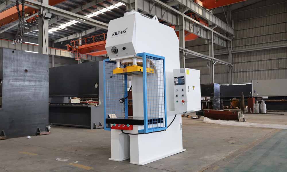
Y41B-100T C-frame hydraulic press machine is a kind of multifunctional machine which has strong generality. It is suitable for the press fitting of shaft components and axle sleeve parts as well as the movements of coining and overprinting. It can also be used to press powder and plastic products which the requirements are not strict. At the same time, it mainly applies to the fields of machine tool, engineering machinery, electrical components, bearings, washing machine, automobile parts and motor components. It can even be used as assembly line. The pressure, stroke, and time of pressure maintaining can be regulated.
2. Work Condition
A),The machine with independent power organization and electrical system,adopts centralized control buttons, adopt PLC programmable controller control process,TPC parameters setting control the stroke, that can make sure the adjustment and semi-automatic operations.
B),The machine's working pressure, stroke scope can adjustment it according to the process.
C),The working environment of the machine is 5~45℃.
D),Power supply adopts 220V,60Hz, 3 phase four wire system,voltage range is 220V±10%,max. relative humidity is 75%.
Structure
This machine is mainly composed of machine body, cylinder, hydraulic system, electrical system working platform, limited process devices, pipes and so on. The structure and function of each part will now be described as follows:
1. Machine Body
Machine body is made up of welded steel plate. Steel body welded with CO2 shielded welding and deal with tempering to ensure high intensity of machine body. To avoid rusting, machine body deal with shot blasting and print with matt paint. To ensure the planarity, verticality and concentricity precision, work table is made in the machine of Boring.
2. Hydraulic Pump Station (Power Systems)
Hydraulic system consists of pumps, control integrated valve, fuel tank, control system and piping components.
- Allpiping connected with high pressure flanges to avoid leakage of hydraulic oil. All the piping have been pickling before welding, soldering and then go through the welding slag, deburring and secondary pickling to ensure clean hydraulic lines.
- Hydraulic systemequipped with reliable sealing, no leakage; major pipe connected with flange and shock measures (shock tube clip).
- Hydraulic oil gauge is installed in the left rear side and the scale display with temperature gauge, oil leveland temperature can be observed. Please stop working and cold oil when oil temperature exceeds 45º.
3. Hydraulic Control System
Equipment operator interface and use of the logo using bilingual interface, console can move freely within a certain range, console cloth with buttons, time relay, etc..
The machine has adjustment and semi-automatic working types, and you can select according to your products requirements.
Please check Diagram-1 to refer to hydraulic principle of hydraulic control system.
Diagram1- Hydraulic control system

4. Electronic System
1). Introduce
The machine adopts AC 220V/60Hz/3 phases power supply. Power transformer will transfer it to 220V voltage for motor and DC 24V for TPC.
The machine has dedicated electrical control cabinet and work station. The work station can be put arbitrary, the operation panel set optional switch, control button and light, that can control the machine. The inner electrical cabinet has switch, thermal relay, ac contactor, time relay, transformer and intermediate relay control circuit. The machine has adjustment and semi-automatic working types, and you can select according to your products requirements. The adjustment mainly used to adjust the machine and molds.
On the situation of semi-automatic, just put the hands run button, then can finished the produce in one time.
Hands run button must put at the same time, and the time can’t be more than 0.5 second, then the machine can working in right way.
Please check electrical Schematic diagram.
Diagram2-Electrical schematic of operation panel

Diagram3-Electrical schematic of PLC

Diagram4-Electrical schematic of Main system

Diagram5-Electrical schematic of hydraulic valves

2) Electric drive device and electrical parameters
- The oil pump rotating three-phase squirrel cage asynchronous motor, the size and specification is as follows:
Y-4-7.5KW-B5 7.5KW ~220V one piece
- The machine hydraulic system of the electromagnetic reversing valve is driven DCwet-type electromagnet; solenoid number is nine, action voltage for DC24V.
- Sign of main technical parameters for the machine electrical data:
Total power: 7.5 KW
Voltage: ~220V
Phase: 3
Frequency: 60HZ
3)Other actions
Emergency stop: In case of emergency status, Operator can click Emergency stop button to stop machine immediately.
4) Electric interlocking and electrical protection device
Main power circuit adopts automatic switch short circuit protection, motor with thermal relay overload protection, control circuit adopts high marks broken small circuit breaker short circuit protection.
Every electrical device has reliable grounding device for special purpose, to ensure safety.
Security and Protection Device
1. Button of Emergency Stop
In case of emergency status, click the Emergency stop button, machine will stop working immediately.
2. Button of Hands Operation
To operate the machine with left and right hands at the same time, the hands limit of synchronization time is 0.5 to 1S
3. Security Sensor Device
There is a security sensor device in front of operation table to protect operator. In the period of machine working, insert your body into security sensor, the machine will be stop and return RAM automatic.
4. Overload protection
Pressure of pressure sensor can be displayed on the TPC. In case of pressure overload 24.7 Mpa, machine stop working automatic, and light alarm with three-color light. To ensure the machine work normal, restart the power of machine.
5. Protection net
To ensure the security of operator, there are a maintenance platform with protection net mounded at the sides of machine.
c-frame hydraulic press Machine Lifting and Installation
1. Lifting
Please read the notes before lifting.
Notes:
- Carefullywipe off the rust oil when the machine arrived at factory.
- Pay attention tothe center of gravity and choice correct lifting holes when lifting parts.
Lifting the press machine to the correct position with lift holes on the top of machine. Please check the diagram-5 of lifting.
Diagram-5 lifting the press machine
To ensure the security of operator, there are a maintenance platform with protection net mounded at the sides of machine.

2. Installation Procedure
Refer to diagram-6 to connect the power cable into electronic box.
Diagram-6 Power cable connection

Notes:
Please change the connection order of L1 L2 and L3 in case of motor running direction is Counterclockwise.
Notice of Machine Test
- Ensure the oil box is clean and all the screw of and screw boltare tight.
- Please clean the oil box before inject hydraulic oil if there is some impurity and water in it. Otherwise, inject hydraulic oil is forbidden.
- Open the oil cover in the back of host machine and inject anti-wear hydraulic oil#46 (about 200kg).Stop injecting when the oil reach the red graduation.
- Check the run direction of fan, ensure it’s run in clockwisedirection and without block. Check the run direction of motor to ensure it running in clockwise direction too. Please start to operation machine one mintues later,after motor run correct.
- Don’t keep the hydraulic system under full pressure status for a long time, to avoid hydraulic components damaged when hydraulic oil in high temperature for a long time.
Acceptance
1.Inspection No.: KLT-S001
Inspect Project: Planarity of upper and lower Worktable
Inspect Method:
2.Inspection No.: KLT-S002
Inspect Project: Parallelism between slider and work table
a, from left to right
b, from front to back
Inspect Method:

3.Inspection No.: KLT-S003
Inspect Project: Verticality between lower side of slider and work table
a, from left to right
b, from front to back
Inspection Method:

Maintenance of c-frame hydraulic press Machine
- Clean the oil box and change the oil per 6 month Don’t change the oil less than 6 months at the first time and second hands oil can be used again after filtration.
- The used rule of hydraulic oil(#46): hydraulic oil must be filtered before used, the capacityof hydraulic oil must reach the indicate place and it’s temperature must keep in [5º, 45º].
- Pressure gage must be authenticate per 6 months.
- Machine long-term disabled, each should be exposed machined surfaces cleaned and oiled.
- The max. pressure is 100T (23MPa) +1T, too large pressure to make the column eccentric strain or other undesirable phenomena occur.
Instruction of Operating Safety
- The operator must understand the structure and features of machine very well, otherwise not be allowed to start the machine.
- Stop machine immediately when c-frame hydraulic press machine has a serious oil spill or work abnormal (action is not reliable, noise, vibration, etc.). and analyze the causes and troubleshoot, Don’t running the machine enforced in justification sickstatus.
- Don’t use the machine in overload pressure status.
- Don’t overload the max. stroke and dies close height must more than 200mm.
- Don’t adjust and repair the mold in work area when the c-frame hydraulic press machine is running. Before installation of mold, open the cylinder to the maximum to the top, locking safety hydraulic cylinder to prevent the slider fall out by themselves to cause personal injury.
Set Technical Parameter (Important)
1.After finish cable connection, please check them again and ensure everything is correct. When oil box is on the top of the host machine, please upper the oil pumping and oil drum at a suitableposition to inject the hydraulic oil. Check the oil capacity in oil tank level display meter, view the oil temperature at the same time.
2.Power on the breaker in electrical box, close the door of electrical box and rotate switch(the left one below) on to power on position.

3.Click button operation panel to run oil pump and start and stop pump immediately. Check running direction of motor, it must be a clockwise direction. Otherwise, please correct it with change the electric phase.


Learn more about our products, please visit and subscribe to our Youtube channel


