Have you ever wondered how sheet metal transforms into intricate shapes? Are you eager to explore the world of press brake machines, versatile tools widely utilized in various industries? Look no further!
Embark on a captivating expedition as we unravel the intricacies of press brake machines, immersing ourselves in technical parameters, classification, and evolutionary strides. Prepare to be captivated by the inner workings of hydraulic transmission circuits and the artistry of synchronized ram control as we delve deep to offer you a panoramic comprehension of this indispensable marvel of metal-forming.
Prepare yourself for an exhilarating journey of knowledge as you fasten your seatbelts and brace for an enlightening experience ahead!
Introduction to the Mighty Press Brake Machine
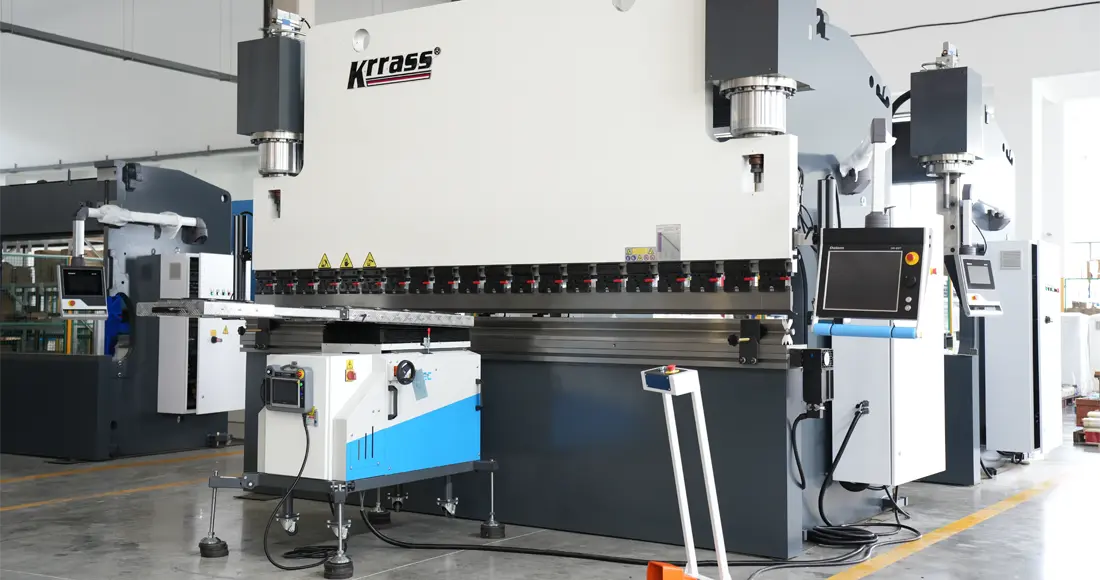
A press brake machine is a powerhouse behind the complete bending of sheet metal.
The sheet metal can be bent into specific cross-sectional geometries with a single ram movement.
Adjusting the press brake dies and repeating the bending process can achieve even more complex cross-sectional shapes.
In the realm of forging equipment, the press brake machine reigns supreme as one of the most widely used metal-forming tools. Its applications span diverse industries, including aviation, shipbuilding, railway, electrical engineering, mining, engineering machinery, metallurgy, automobile, agricultural machinery, light industry, instrumentation, textile, electronics, etc.

As human civilization progresses, demanding higher-quality materials, the industrial sector and everyday life industries require high-precision press brakes. These machines find their place in the production of high-speed rail, electric power, elevators, decoration, machinery manufacturing, kitchenware, security products, and more.

Vital Technical Parameters of the Press Brake

- D – Throat depth
- E – Daylight (distance from top to top of the table)
- Ram stroke – Maximum extension distance of the cylinder
- Reasonable distance - a vital parameter, refers to the measured expanse spanning from the inner edges of the steadfast left and right columns.
- M – Worktable height
- b – Total height of the lower die
- d – Effective height of the top punch
- k – Clamping device height of the top punch
- Ram speed – Fast down, work feeding, return speed
Choosing the Right Press Brake Machine: General Calculation Method

Calculation formula:

- P – Bending force (in kilonewtons)
- S – Sheet thickness (in millimeters)
- S – Sheet width (in meters)
- V – Width of the lower die opening (in millimeters)
- 650 – Calculation coefficient
Note: The above formula yields results based on a Q235 ordinary steel plate with a tensile strength of 450-500 N/mm2. When bending different materials, the bending force is the product of the above results and specific factors.
| Bronze (soft) | 0.5 | Stainless steel | 1.5 |
| Aluminum (soft) | 0.5 | Chromium molybdenum steel | 2.0 |
Different lower die openings ("V") correspond to various plate thicknesses.
| S | 0.5~2.6 | 1.5~8 | 8~12 | >12 |
| V | (6~8)S | 8S | 10S | 12S |
Remember: Selecting a larger die opening "V" during bending reduces the required bending force and increases the inner radius of the bent workpiece.
Diving into the Classification of Press Brakes
The Upward-Acting Hydraulic Press Brake Machine is the most widely employed model in the current market, favored by numerous press brake manufacturers.
At the heart of this machine lies its defining characteristic—impeccable synchronization and precision control of the ram. This key element stands as the linchpin, dictating not only the operational efficiency but also the exquisite quality of the final output.
Based on the different ram control methods, press brake machines can be classified into two types:
- Torsion Shaft Synchronous Press Brake Machine
- Electro-Hydraulic Synchronous Press Brake Machine
Embarking on the Development of Electro-Hydraulic Proportional Technology
During the latter part of WWII, the speed of jet fighters continually increased, necessitating advanced control systems with higher requirements for speed, dynamic accuracy, and dynamic rate.
In 1940, the first electro-hydraulic servo system made its appearance in aircraft. The 1960s witnessed the development of various types of electro-hydraulic servo valves, marking the maturity of electro-hydraulic servo technology.
Yet, as the late 1960s approached, the demand for electro-hydraulic servo technology in civil engineering experienced an unprecedented surge. Yet, traditional electro-hydraulic servo valves imposed strict requirements on fluid medium and consumed substantial energy, resulting in high manufacturing and maintenance costs.
In response to the pressing demands of engineering and the quest for dependable electro-hydraulic servo control technology, the 1970s witnessed an era of remarkable strides in electro-hydraulic proportional control technology. Concurrently, the realm of industrial servo control technology underwent a profound transformation.
Electro-hydraulic proportional technology seamlessly combines hydraulic power transmission with the flexibility and precision of electronic control. With the progress of numerical control technology and the availability of reliable, balanced hydraulic components, electro-hydraulic proportional control technology has become widespread. One notable application lies in the synchronous control of press brake machines.
Exploring the Fundamentals of Hydraulic Transmission Circuitry
The foundation of hydraulic transmission lies in Pascal's principle.

The pressure remains equal at all points in a closed cavity formed by an oil pump, hydraulic valve, pipeline, and oil cylinder.
The hydraulic system generates oil pressure based on the load of the oil cylinder, adjusting accordingly.
A hydraulic transmission circuit typically consists of an oil tank, oil pump, hydraulic valve group, oil cylinder, and connecting pipes.
The oil pump draws oil from the tank, creating a flow that propels the movement of the oil cylinder through the hydraulic valve group.
By controlling the flow direction and pressure of the oil, the hydraulic valve group ensures that the oil meets the movement requirements of the machine tool.
Unleashing the Power of Hydraulic Transmission in Press Brakes

The heartbeat of a press brake machine is divided into three distinct working conditions, each with its role to play:
- Lightning-fast: This condition propels the ram downward at a rapid pace.
- In the trenches: The working condition sees the ram move downward at a controlled speed, completing the bending process.
- Return to the base: The ram moves upward swiftly, completing the entire machine cycle.
These working conditions are defined by three specific points that determine their starting and ending positions:
- Top dead center: The highest amount of the ram.
- Speed change point: The ram transitions from fast-moving to working speed.
- Bottom dead center: The lowest amount of the ram.
Consequently, the ram operates at three speeds throughout its cycle:
- No load speed: Swiftly descending from the pinnacle of stillness to the precipice of velocity at the speed change juncture.
- Working speed: With precision and control, the ram glides downwards from the speed change point to the bottom dead center, skillfully bending the workpiece.
- Return speed: Ascending rapidly from the depths of the bottom dead center to the zenith of the top dead center, accomplishing a complete revolution of the machine's cycle.
These three speeds and the positions of the specific points can be adjusted using the numerical control system, offering precise control over the machine's operation.
In the case of an Electro-Hydraulic Synchronous CNC Press Brake Machine, there is an additional critical point known as the clamping point. This point corresponds to the upper surface of the sheet on the lower die and is automatically calculated by the numerical control system. The bending of the workpiece commences from this point.
Hydraulic oil serves as the transmission medium for hydraulic systems, directly impacting the performance and lifespan of the machine. In particular, the Electro-Hydraulic Synchronous CNC Press Brake Machine has a proportional servo valve, demanding even higher quality hydraulic oil than other bending machines. Users are advised to filter the hydraulic oil at least once a year regularly.
Synchronization Principles in Different Press Brakes

The Torsion Shaft Forced Synchronization Control Technology takes center stage in the ram operation in a bending machine.
The synchronous shaft is situated on the left and right panels of the machine's frame interconnected with the ram through a connecting rod.
While in action, any discrepancy in speed between the two ends of the ram sets in motion a captivating twist along the synchronous shaft facilitated by the interconnecting rod. The rigid synchronous shaft exerts a counterforce, reducing the ram's rate and ensuring synchronized movement (Y1, Y2) while maintaining a parallel alignment with the worktable.
Attaining impeccable precision in ram positioning is made possible through the innovative application of Rigid Positioning Control Technology. This innovative approach incorporates mechanical stops cleverly integrated within the left and right oil cylinders. These stops halt the downward movement of the piston rod upon contact with the automatic stop's locating surface, thereby controlling the final stroke position of the oil cylinder.
By synchronously adjusting the mechanical stops of the left and right oil cylinders using the connecting rod, the relative parallel state of the rams (Y1, Y2) to the worktable is controlled.

In contrast, the Electro-Hydraulic Servo CNC Press Brake Machine utilizes two oil cylinders to drive the ram's up and down movement during bending. Achieving synchronization between the two cylinders and accurate positioning of the bottom dead center is paramount.
The Electro-Hydraulic Servo CNC Press Brake Machine employs the CNC system to precisely control the synchronization of the two oil cylinders and ensure accurate positioning at the bottom dead center. This ensures smooth ram movement and precise alignment at the bottom dead center.
Uninterrupted monitoring of the ram's position is accomplished by meticulously employing grating rulers on either side of the machine, ensuring precise and real-time feedback to the CNC system. The numerical control system compares the feedback data from the two grating rulers and adjusts the proportional servo valve in the synchronous valve groups. This control mechanism regulates the valve's opening size and the oil intake of the oil cylinder, maintaining the ram's operation within an acceptable error range. Consequently, the rams (Y1, Y2) run in sync and maintain a parallel alignment with the worktable.
Additionally, the numerical control system compares the feedback data from the grating ruler with the system's set bottom dead center position, ensuring accurate alignment at the bottom dead center.
The Electro-Hydraulic Servo CNC Press Brake Machine utilizes a complete closed-loop electro-hydraulic servo control technology for synchronization, with the ram's position signal fed back to the numerical control system via the grating rulers on both sides. The numerical control system then adjusts the synchronous valve's opening size and oil intake of the oil cylinder, ensuring synchronized movement (Y1, Y2) and parallel alignment with the worktable.

Synchronous schematic diagram of electro hydraulic synchronous CNC hydraulic press brake machine
In the event of positioning errors on both sides of the ram, the numerical control system sends correction instructions to the two synchronous valves to maintain the parallel alignment of the ram with the worktable.

The diagram illustrates the components of the synchronous system in the Press Brake Machine, primarily encompassing hydraulic oil control and electrical signal transmission.
The pressure oil is regulated by the two synchronous valve groups, entering the oil cylinders to drive the synchronized movement of the ram. Unceasing vigilance is maintained over the ram's position through the vigilant gaze of grating rulers adorning both sides, diligently relaying this vital information to the CNC system.
Harnessing the power of advanced algorithms and computational prowess, the CNC system meticulously scrutinizes and computes the gathered data, orchestrating precise control over the two synchronous valve groups through the adept servo amplifier. Furthermore, the feedback signal emanating from the proportional servo valve's spool position is meticulously received, analyzed, and integrated into a dynamic closed-loop control system, perpetuating seamless synchronization and unwavering precision.
Throughout the ram's movement, the numerical control system sets parameters according to the program. It dynamically controls the synchronous valve group using the grating ruler's feedback and the proportional servo valve's spool position feedback, achieving synchronized operation and accurate positioning at the bottom dead center.
Thus, the Electro-Hydraulic Synchronous CNC Press Brake Machine's synchronization control system predominantly consists of the CNC system, grating ruler, and proportional valve.

As depicted above, the bending principle of the Electro-Hydraulic Synchronous Press Brake Machine is similar to that of a standard Press Brake Machine. With utmost precision, the former method regulates the desired bending angle by skillfully modulating the depth of sheet pressing within the lower die cavity, either through the deft maneuvering of the top punch or by molding the workpiece to match the angle of the die.
The critical difference lies in the ram's control mode, governed by the numerical control system through the electro-hydraulic proportional valve and feedback from the grating ruler. This establishes a complete closed-loop, digital control mode for precise bending depth.
Differentiating the Two Synchronization Modes in Press Brakes
The conventional press brake machine relies on a torque tube to ensure synchronous movement of the ram. In contrast, the electro-hydraulic press brake machine achieves synchronization through hydraulic oil circuit balance.
The torsion shaft press brake operates on an open-loop control system, while the electro-hydraulic press brake employs closed-loop control.
Advantages of the Electro-Hydraulic Synchronous Press Brake

The electro-hydraulic press brake machine boasts several distinct advantages:
- Fully closed-loop control: The system enables continuous monitoring and management of the cylinder's stroke. If the cylinder begins to tilt, the system issues prompt commands based on the readings from scales positioned on either side of the cylinder. These commands, in turn, adjust the proportional valves to maintain synchronization between the cylinders.
- Differential loading: A remarkable feat is accomplished within the electro-hydraulic press brake machine: one cylinder valiantly carries the burden of full load while its counterpart operates gracefully in a zero-pressure, off-load pressurized state.
- Flexibility in bending angles: The electro-hydraulic synchronization system allows the ram to tilt at various angles, facilitating bending workpieces at different angles - an advantage not in traditional press brake machines.
- Automatic pressure regulation: The system automatically adjusts the pressure in each operating condition using the proportional pressure valve based on system parameters.
- Smooth speed transition: The electro-hydraulic press brake machine transitions from fast to slow speed, reducing hydraulic impact and enhancing system stability.
- Precise cylinder positioning: The electro-hydraulic press brake machine's precise control of the cylinder position enables bending with the same die at different angles, making it an exceptionally versatile machine tool.
- Automation and error reduction: Harnessing the power of automated control, the entire process transforms, leaving behind the errors associated with human intervention. Each working condition becomes a malleable entity, capable of being meticulously adjusted and flawlessly corrected through carefully manipulating CNC parameters.
In conclusion, the electro-hydraulic press brake machine enhances production efficiency, increases part accuracy, and transforms the device into a valuable tool for operators.
Critical Components of the Electro-Hydraulic Synchronous CNC Press Brake Machine
The electro-hydraulic synchronous CNC press brake machine comprises three main components:
Electric Control System
This system encompasses the electrical control cabinet, numerical control system console, and operator station.

Main Machine
The main machine consists of the oil cylinder, hydraulic system, grating ruler position feedback system, ram, frame, and various tools. The hydraulic system's central component incorporates internal gear pumps from Voith in Germany. The main machine also features a range of valves, including filling valves, cartridge valves, lifting valves, proportional relief valves, electromagnetic directional valves, proportional pressure valves, and proportional servo valves.

Auxiliary Mechanism
The additional mechanism includes various functional components that can be selected based on user requirements. These components may include a worktable compensation mechanism, back gauge, quick-release die clamping device, material carrier, oil temperature control system for cooling or heating, photoelectric protection device, centralized lubrication system, and more.
Press Brake Backgauge
The press brake machine's axes are typically configured according to the workpiece processing requirements.
- X-Axis: This semi-closed-loop mechanical movement axis controls the rear stop. When equipped with the X1 axis, it becomes the control axis for the left finger.
- R Axis: This control axis manages the vertical lift of the rear stop.
- Z1 Axis: This mechanical axis controls the lateral movement of the left stop fingers on the back gauge beam.
- Z2 Axis: This mechanical axis governs the lateral movement of the right stop fingers on the back gauge beam.

Precision in Bending
Angle and Straightness Errors

Analysis of Stress and Strain in Sheet Metal Bending

Analyzing Straightness Errors

After the bending process, the edge of the bent workpiece naturally exhibits deflection, which is measured by its maximum deflection (δ).
Based on stress analysis, the deformation zone experiences tensile stress on the outside and compressive stress on the inside. These opposing forces generate a bending moment necessary to maintain the workpiece's straightness during bending. However, this moment disappears once the bending process concludes, causing the workpiece to deflect upwards.
The longer the bending plate, the greater the deflection (δ). Similarly, a narrower plate width produces a more significant deflection (δ).
Nevertheless, reducing the bending angle from 150° to 90° decreases the deflection (δ).
Moreover, as the plate thickness increases, the deflection (δ) also increases proportionally.
Applying pressure to the bending sheet's edge, such as through correction bending or three-point bending, can enhance the workpiece's straightness.
Influential Factors on Bending Accuracy
The primary factors affecting bending accuracy in a press brake machine include press brake stiffness, bending mode, and bending force.
Press Brake Stiffness
How can we determine the stiffness index during press brake machine design?
Deflection Deformation of the Press Brake Machine

Bending Mode
Air Bending

Three-Point Bending

Coining

Bending Force
How does the bending force change during the bending process?
Free Bending with sharp angle punch
As depicted in the accompanying figure, the free-bending mode utilizes Q235 steel, which exhibits ideal elastic-plastic behavior with linear hardening. The material's yield strength (σS) is 250 MPa, and its hardening modulus (tangent modulus) is 1050 MPa.

The ANSYS analysis results are as follows:

Bending Force Curve:

Analytical Method Results:

Obtuse punch Bending
The accompanying figure illustrates that the upper die features a wide R180 arc, and the sheet material is X80. This material exhibits ideal elastic-plastic behavior with linear hardening, possessing a yield strength (σS) of 552 MPa. The hardening modulus (tangent modulus) is 840 MPa.

The ANSYS analysis results are as follows:

Bending Force Curve:

Design Principles and Implementation of Convex Worktable
During press brake machine operation, deformation occurs due to force application at both ends. This force, generated during the bending process, causes deformation in the ram and worktable, resulting in inconsistencies between the workpiece's two ends and its central angle.
The finite element method, known for its speed and accuracy, is widely employed to analyze the press brake machine.

Convex curve of a 100-ton, 3-meter press brake machine obtained through the finite element method:

Several methods can compensate for deflection deformation:
- Saddle-shaped worktable with fixed deflection compensation.
- Top punch wedge compensation.
- Worktable cylinder compensation in pressure control mode.
- Automatic payment of the worktable in position control mode.
Worktable Cylinder Compensation
The worktable features a three-layer splint design, incorporating compensating oil cylinders throughout the structure.
When pressure is applied to the compensating cylinders, the middle splint of the three-layer sling is pushed up, compensating for deformation.

Mechanical Compensation of the Worktable
To control the position, compensation is provided at the corresponding point during bending to counteract the machine's elastic deflection deformation.
Automatic compensation is achieved through a group of wedges with inclined planes capable of providing reverse payment.

Before bending loading, pre-convex state:

After loading the bending, the actual compensation state changes:

Loading simulation animation of the convex worktable:

Driving mode of the convex worktable:

Electric Control System
The electric control system serves as the driving force behind the machine tool, controlling every action and function.
Amidst the rhythmic dance of a CNC press brake machine, the solenoid valve wields authority over the ram's graceful movements and adaptability to shifting working conditions. Serving as the sentinel of control, the electric control system dutifully assumes the responsibility of altering the power dynamics within the solenoid valve, ensuring seamless transitions amidst diverse operational scenarios.
The solenoid valve is the electric system's executing component and the hydraulic system's control component. The electromagnetic valve connects the electro-hydraulic system and the hydraulic system's electrical control.
For traditional torsion shaft machine tools, simplicity reigns within the electric control system, as it solely necessitates mastery over the ebb and flow of power for a handful of solenoid valves. The intricate dance of synchronization holds no dominion over the operation process, allowing for a more straightforward control framework.
However, in the case of electro-hydraulic press brake machines, the synchronization of the two cylinders is controlled using a servo valve due to changes in the synchronization mode. The electric control system solves the challenge of synchronous control.
Therefore, any electro-hydraulic servo press brake machine must be equipped with a numerical control device that continuously detects the ram's position at both ends, calculates the servo valve's opening at each moment, and controls the servo valve amplifier to ensure synchronization during operation. Two proportional servo valves and two grating rulers are essential for detecting and preventing the position on both sides.
Behold the intricate symphony of the electric control system within the electro-hydraulic servo press brake machine, vividly depicted in the following schematic diagram.

The schematic diagram focuses solely on the control of the press brake machine's ram.
Torsion Shaft Numerical Control System
Standard CNC systems for torsion shaft synchronous press brake machines include:
- E21
- E300P
- DA41T
Electro-Hydraulic Numerical Control System
Renowned for their exceptional quality and reliability, the Cybelec brand from Switzerland and the Delem brand from Holland have earned widespread acclaim in the realm of electro-hydraulic numerical control systems. These esteemed brands stand at the forefront, being the most widely adopted choices in the industry.
- DA53T
- DA58T
- DA66T
- DA69T
Immerse yourself in touch control, for it has become the reigning champion among mainstream systems. Delve deeper into the intricacies of this fascinating technology by visiting the following page, where a treasure trove of information awaits your eager exploration.
In Conclusion
As we conclude this enlightening journey, you now possess a profound comprehension of the press brake's inner workings. Yet, it is essential to acknowledge that the realm of press brake machines and toolings harbors even more knowledge. May these blog posts serve as a wellspring of valuable insights, bestowing you countless benefits in your pursuit of excellence.


