This manual gives a detailed introduction to the use of fiber laser cutting machine FSCUT3000 Control System, including technical features and installation instructions, etc. If you want to know moreinformation about TubePro cutting control software, TubesT/TubesT-Lite 3D nesting software and BCS100 height controller which are used in FSCUT3000 Control System, please refer to related manual. For other matters you can contact us directly. Operating personnel should read the manual in detail which will be helpful for a better use of the product.
1.Product introduction
1.1 Brief introduction
FSCUT3000S Control System is an open loop laser cutting control system of high performance developed by Shanghai Friendess Company. It is widely used in the field of metal and non-metal laser cutting area and gained popularity among the customers at home and abroad for its outstanding performance in medium power laser cutting application.
Please read through this manual carefully before operation.
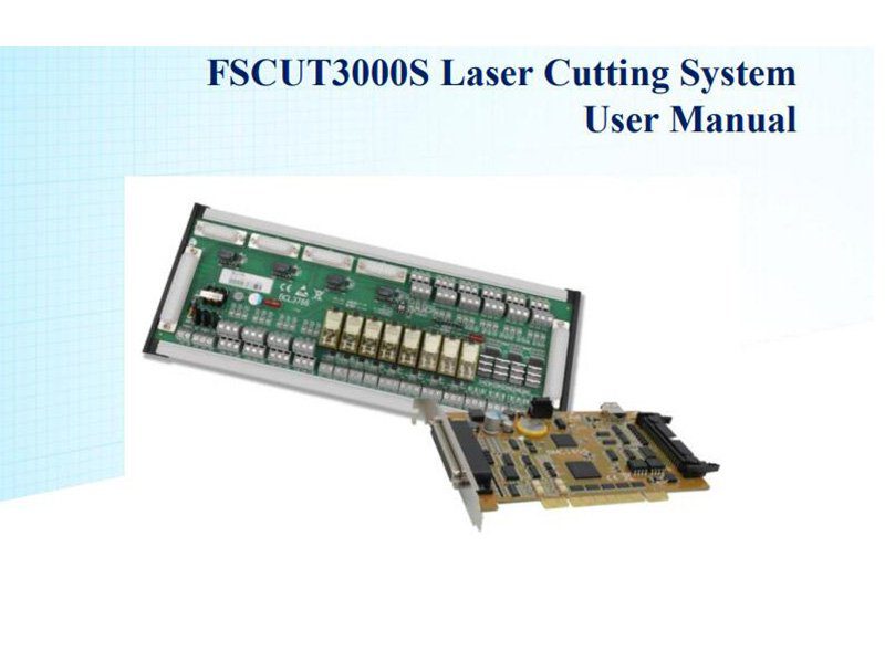
FSCUT3000S Laser Cutting System contains the following accessories:

1.2 System Connection Diagram
BMC1805 card adopts PCI interface. Dimension:213mm*112mm.There are 2 sockets on control card, JP1 is type DB62M socket connected by C62-2 cable to BCL3766 IO terminal board ; JP2 is extension socket connected with flat cable to the back of the computer case first then connected to BCL3766 IO terminal board by C37-2 cable.
Wiring diagram shown below:

1.3 Technical Reference

1.4 Control Card Installation
1.4.1 Install steps
Please wear anti-static gloves to prevent possible electrostatic damage to the motion control card.
- Turn off computer, insert the control card into PCI slot, and fix the control with screw; After start up computer, "Find New Hardware Wizard" pops out and click "Cancel" button, as shown below. If this dialog box does not appear, indicating that the card is not inserted properly, please repeat the first step.
- After start up computer, "Find New Hardware Wizard" pops out and click
"Cancel" button, as shown below. If this dialog box does not appear, indicating that the card is not inserted properly, please repeat the first step.
- Install TubePro software, meantime the driver of BMC1805 card and
softdog will be installed automatically. - Close the anti-virus software during installation in case it's misdiagnosed as virus and fail the installation process. Pass all the message box during the installation.
- Open device manager to confirm installation is succeed

1.4.2 Troubleshooting
- If "Find New Hardware" dialog box does not pop out after start up computer or control card does not shown in device manager, indicating that the control card is not inserted properly. Please replace the PCI socket or computer, insert the control card and reinstall software.
- If the device has a yellow exclamation mark, double-click to open its attributes page, and select "Detail Information" as shown.


2. BCL3766 Connection
2.1 BCL3766 Connection Instructions


2.2 Signal Type
2.2.1 Input Signals
The input signal includes: Positive and negative limit switch, origin switch, general input signal. Input signal to BMC1805 card is low level active: It supports normally open and normally close input patterns (signal logic setting is in TubePro 'config tool'). When set as normally open, input is valid when conducting with 0V.
When set as normally closed, input signal is valid when disconnected with 0V.
The input logic can be switched by jump wire, supported by IN13, IN14, IN15 inputs. There are 2 states of jumper, ACT_LOW state shown in image, indicates low level active; ACT_HIGH state shown in image, indicates high level active. Default state is ACT_LOW.

The typical wiring of optoelectronic switch shown below, it must be NPN type 24V switch.

The typical wiring of contact switch shown below.

The typical wiring of magnetic switch shown below, it must be NPN type 24V switch.

2.2.2 Relay Output
The load capability of the relay outputs in BCL3766 are: AC 250V/5A、DC 30V/5A. Support to control AC 220V load of small power. If you need to carry high power load, please connect external contactor.
The wiring between relay output and contactor as shown below:

2.2.3 Thyristor Output
There are 12 thyristor outputs OUT9~OUT20 on BCL3766 IO terminal board which can directly drive DC 24V device, capacity of each output is 500mA.Wiring diagram shown below:

2.2.4 Differential Output
The pulse instruction form send to servo driver is "pulse + direction, negative logic". Highest pulse frequency:3MHz。 Pulse pattern shown below:

The differential signal output pattern shown below:

2.2.5 Analog Output
2 analog outputs of 0~10V

2.2.6 PWM Output
There is one PWM output on the BCL3766 terminal board, which can be used to control laser average power output. PWM signal level is 24V or 5V as option. The duty cycle is adjustable from 0%~100%, the highest carrier frequency 50KHz.The output of the signal is shown in the following figure:

It’s highly recommended that connect PWM+/- with relay in series to prevent laser leakage by interference. See details in section 2.5.In addition, set the right voltage of PWM signal. Select 5V or 24V by DIP switch.
2.3 BCL3766 Instructions
2.3.1 External Power Supply
BCL3766 requires 24V DC external power supply. 24V and COM input terminal connect with switch power supply 24V and OV output.


+24V、0V: Supply 24V DC power for servo driver.
SON: Servo ON, output servo drive enable signal;
ALM: Alarm, receiving servo driver alarm signal;
PUL+、PUL-: Pulse (PULS), differential output signal;
DIR+、DIR-: Direction (DIR), differential output signal;
A+、A-、B+、B-、Z+、Z-: Encoder three-phase, input signal.
You can switch active level of SON and Alarm signal by jump wire;

2.3.3 Servo Control Signal Pin Wiring
FSCUT3000S motion control system adopts 'pulse+ direction' signal pattern to control servo driver. The highest signal frequency can reach to 3Mpps.
It's recommended that select high speed differential signal. Set pulse equivalent within 1000~2000 to improve the interpolation precision.


2.4 Wiring Diagram

2.5.2 CO2 Laser Connection
Here take the example of NT-3200SM model of Valley Nuo.

2.5.3 IPG-YLR series wiring diagram

2.5.4 German IPG_YLS Series Wiring Diagram

3.Platform Configuration Tool
3.1 Installation
Configuration tool will be installed automatically in TubePro software installation.
In Windows 'Start' menu-'All programs'-'TubePro Laser Cutting Control System' click 'Machine config tool' the icon is .
![]()
3.2 Password
You have to input password to start config tool.
Initial password 61259023 click Ok open the config tool.

Note: Parameter setup must accord with the actual mechanism structure, wrong setting will cause unknown serious consequences! In config tool, input ports are in yellow color, output ports are in green color.
3.3 User interface
Click buttons at the top of the screen you can enter in different parameter page like picture above.
For example: Click 'Machine' enter into the mechanism parameter setting page.
Users can click 'Import' to directly load the configuration file; Click 'Save' preserve the setting.

Note:
- Data folder contains all configuration information of TubePro.
- You can backup file in config tool-file-parameter backup.
3.4 Machine Mechanism Configuration

Servo alarm logic: Select the signal logic as normally open or normally close.
Speed: The maximum speed and acceleration allowed.
Return origin direction: You can set different return origin direction according the axis structure.
Origin signal: If user selects limit switch, it will sample limit signal when execute return axis to origin function. Note: B axis must separate limit switch and origin switch, and sampling origin signal when execute return origin process.
Z phase signal: Whether use Z phase signal decide the two different process of return origin. The corresponding process image will be displayed at lower position.
Rough speed: Axis will find origin switch 2 times. The first time to find origin signal at fast speed, recommended value of XY is 50mm/s, B axis is 30RPM.
Fine speed: Axis will find origin the second times at fine speed, recommended value is 10mm/s, B axis is 3RPM.
Fallback: The distance can keep machine origin not too close to limit switch.
Limit logic: The signal logic of X, Y, B axis limit and origin switch. Limit switch is not necessary for B axis.
B axes return origin separately: B axes decoupled then return origin separately.
3.5 Laser Configuration
TubePro supports most of the laser in market includes YAG, CO2, IPG, Raycus, SPI etc., there are different parameter settings for each type laser.
3.5.1 CO2 laser configuration

Mechanical shutter: Output port to control mechanical shutter.
Electronic shutter: Output port to control electronic shutter.
Response input: After mechanical shutter open will send a response signal to this port.
Laser model: Laser model 1 and model 2 will form the laser as continuous wave, gate or strong pulse.
DA port: There are 2 analog DA ports on BCL3766 terminal board, choose either of them to control laser peak power.
DA voltage range: The analog voltage range to control laser power.
Minimum power: The minimum power of the laser.
3.5.2 IPG Laser configuration

PWM Enable: Assign any of the relay output to switch PWM signal on and off.
This can prevent laser leakage or false triggering.
DA port selection: There are 2 analog DA ports on BCL3766 terminal board, choose either of them to control laser peak power. When use RS232 or network control doesn't use DA port.
IPG Fiber Laser Configuration:
Remote start-up button:
When switch key to remote control mode, you can startup laser by remote button.
Select this option you have to assign an output port for remote control button. (It is not recommended to use this function, which might cause laser error)
IPG remote control:
When enable IPG remote control mode, TubePro will monitor the laser status in real time and realize the functions including laser emission control, guide beam and set laser peak power etc. When you use network or RS232 control laser, DA setting won't take effect.
IPG provides serial and network communication methods, users can set serial port or IP address under the circumstances. If the communication between PC with laser and PC with BCS100 both choose network communication, the network segment cannot be repetitive. For example, the segment of BCS100 is 10.1.1.x. Laser can set 192.168.1.x. It's recommended to use network communication control laser. If use serial communication the serial cable shielded layer must be well grounded.
3.5.3 Mars/Rofin/RayCus/SPI/GSI/JK laser configuration

The configuration of Mars, Raycus and SPI are similar and support serial communication.
Debug mode: Enable debug mode, it will show communication code on TubePro message window at bottom of screen.
3.5.4 Other Brand of Laser

Laser enable: This related with the Emission button in TubePro control panel.
Standby: This related with the Emission button in TubePro, assign this signal there will be an extra output to open shutter.
Delay: This related with the Emission button in TubePro, the delay of enabling laser.
3.6 BCS100 Configuration

If you choose to use BCS100, only need to set IP address in TubePro config tool, which must be the same with the network address in BCS100.
Details setting IP see in BCS100 manual P2.5.6.
BCS100 demo: When select this mode, users can set related parameters in TubePro without connect with BCS100.
3.7 Gas Configuration

Master Valve: Output to turn on/off cutting gas.
Air (High pressure): Output to turn on/off air.
O2 (High pressure): Output to turn on/off O2.
N2 (High pressure): Output to turn on/off N2.
DA Gas Control: Users can choose one of the DA ports on BCL3766 for gas control.
Max DA pressure: The maximum gas pressure pass proportional valve.
3.8 Chuck

Enable Double chucks auto-feed: the solution that to cut longer tube in short motion range. Require mechanical structure that mid-chuck is hollow structure and mounted with assist chuck with clamp jaws.
Assist chuck: To assist-clamp the tube in chuck center. It's recommended that select 'No Y/B axis Jog with Mid assist chuck' in case of chuck damage. It means when mid-chuck jaws clamped tube, forbid Y and B axis motion functions.
Gas Assist DA: Assign one of the DA ports on BCL3766 to control gas pressure of chuck.
Chuck Type: Chuck types that FSCUT3000S system supports contain electric chuck and pneumatic chuck, from which pneumatic chuck divides into ordinary structure chuck and DaiRuiKe chuck with seal pin structure.
Seal Pin: The DaiRuiKe chuck with seal pin structure can only be used as mid-chuck in 3000S system. One thing to note about DaiRuiKe seal pin structure is that after B axis (chuck) return origin the seal pin must aim at inlet on the rotate body of chuck. After seal pin inserted in air inlet, chuck is not allowed to rotate until seal pin pulls out in case of chuck damage.
Clamp action: Select 'open', program will consider the initial status of the output is close.
Clamp outport: This output will send command of clamp signal.
Default ok time: The time required to complete clamping actions.
Loose action: Select 'open', program will consider the initial status of the output is close.
Loose output: This output will send command of un-clamp signal.
Default ok time: The time required to complete un-clamping actions.
Close output when ok: Program sent clamp and un-clamp output signal then close the output after this time interval.
Y extra motion range: When the tube cross section or mid-chuck status match the condition, Y axis extra motion range will be available.
Chuck assistant actions: Limit Y speed when mid-chuck loose: this function applied in the case that main chuck cannot drag the tube in high motion speed when mid-chuck in loose state. Forbid main chuck loose at specified position: this applied in the case that clamping jaws of main chuck hit the mid-chuck.
3.9 Holder

Holder Type: The holder driven by cylinder defined as 'IO holder', driven by servo motor defined as 'Follow up holder', driven by servo motor and cylinder defined as 'Cylinder follow type' in TubePro program.
Holder auto-up enable: Holder can lift up automatically when user enable this function and set lift up position. When Y axis coordinate smaller than this position holder will lift up. When assign a 'holder auto up' input, only when this input signal activate and Y axis coordinate smaller than auto up position that holder will lift up automatically.
Limit Y speed in holder-down range: Program will limit Y axis dry-run speed in the range of holder drops down. Limited speed ≈ 0.9 *(limit position - down position)/default Ok time.
Up parameters:
Up action: Choose open or close this signal port to control holder lift up.
Up outport: Assign the output port to control holder lift up.
Up inport: When this signal port valid, program will consider holder has reached position.
Inport logic: The signal logic of up-inport.
Default ok time: Controller sent holder lift command, after this time interval it will consider holder has reached position.
Down parameters:
Down action: Choose open or close signal port to control holder drop down.
Down outport: Assign the output port to control holder drop down.
Down inport: When this signal port valid, program will consider holder has reached position.
Inport logic: The signal logic of down-inport.
Default ok time: Controller sent holder drop down command, after this time interval it will consider holder has reached position.
Holder down position setting:
Down position: When Y axis reached this position, program will send holder drop down signal.
Limit position: The limiting position Y axis can reach when holder not drop down in position.
Alarm inport: When this signal port active, program will generate holder alarm.
Alarm logic: Signal logic of alarm.
Close output when ok: When holder lift up or drop down reached position, close.
Note:
1. If enable soft limit function and set 'auto up position' as 0, holder will not lift
up at Y=0 position.
2. If use single output to control holder up and down, output will not close when
holder has reached position.
3.10 Alarms

3.10.1 Warning message
Display the warning message in yellow color when machine is running. You can customize the warning message.
3.10.2 Emergency stop button
Assign an emergency input port, when this signal port turns active program will generate emergency stop alarm.
3.10.3 Diagnose mode
When diagnose input port turns active, program will enter in diagnose mode, under which it will limit Z/Y/X axis speed and laser burst PWM.
3.10.4 Safe SIG port
When this signal port turns active, program will consider Z axis is in safe position. Otherwise program will generate 'Z axis not in safe position' alarm and disable Z axis motion function.
3.10.5 Custom alarm
Users can add customized alarm and edit alarm name, assign signal pin and select signal logic. Commonly used alarms are gas low-pressure, water temperature too high,
and laser head collision etc.
Note: All alarm status will be released in 2 seconds automatically after alarm signal eliminated.
3.11 General input

Click 'Features' button, users can select function item and assign an input port to the function.
Part of the function items have sub-function items, take 'Laser control' for example:

Select the function item as needed.
As shown below.

3.12 General output

3.12.1 Output Assignment
Aiming: Output to control guide /pilot laser.
Working: Assign this port as indicator light of machining status. The indicator will be flashing when machine is in machining status.
Alarm Signal: Assign this port as indicator light of alarm, the indicator will be flashing when there is alarm.
Lasering: Assign this port as indicator light of laser firing status, the indicator will be flashing when laser is firing.
Alarm Tone: Assign this port as alarm bell, when there is alarm detected alarm bell will be ringing.
Light flashing: Enable this function users can customize the interval of indicator light turns on and off to realize the flashing effect.
3.12.2 Auto Lubricate
Select 'Lubrication by time' mode, it will start time counting since TubePro software opened and open the signal output at each cycle and maintain a pre-set 'duration' time; Select 'Lubrication by distance' mode, it will start counting running distance since TubePro software opened and open the signal output at each cycle and maintain a pre-set 'duration' time;
3.12.3 Custom Output
Customize the output port. Assign an output port there will be a control button of the same displayed in TubePro CNC page. The control mode of the button can be contact or self-lock.
3.12.4 Position-compare Output
Used in automatic application, when axes mechanical/program coordinates meet the specified conditions it will open the output port to realize some automatic actions.
3.13 Wireless Remote

In FSCUT3000S system, direction of Y axis defined as positive when move towards laser head and linked with ↑ button on WKB remote. In TubePro config tool-WKB select ‘Reverse left-right’ press ↑on WKB Y axis will move to the opposite of laser head.
In this page you can set functions of 6 compound buttons. Press K button only, it will execute the function set in green zone. Press Fn+K together, it will execute the function set in blue zone.
3.14 CNC Panel

In TubePro config tool- CNC Panel you can activate BCP5045 panel. When use BCP5045 in standalone environment, TubePro program will pair BCP5045 Mac address automatically. When use BCP5045 in LAN environment, please enter the device ID number of BCP5045.There are 12 custom buttons on BCP5045 which can be assigned for pallet changer control or other PLC control.
3.15 Focus Control

Focus range: Set software limit and travel range.
Focus position at ORG: The focus scale at origin position.
Pulse per unit: Command pulses send to servo correspond with focus moving distance.
High speed: The speed to find origin switch.
Low speed: The speed to relocate the origin switch after find the origin in high speed.
Return origin direction: Negative direction is upward, positive direction is downward.
Origin signal: Use limit switch to sample the origin signal.
Rollback distance: After find the origin switch it will move backwards a distance.
Jog speed: Speed of jogging axis driving focus.
Locate speed: The speed of axis driving focus.
Acceleration: The acceleration of axis driving focus.
3.15.1 Precitec-ProCutter
Cypcut with BCS 100-pro can support ProCutter perfectly. Setting is recommended as below: One DA and one 24V output required to control focus position; One 24V output required to execute return origin action. Provide 24V power supply to pin 1, 2 and pin 3, 4.

3.16 IO list
You can check all input and output assignment in this page and customize the port name. Customized name will be shown in blue color.

4.Electrical System Debug
4.1 Power Supply Debug
Connect BCL3766 with BMC1805 card by C62 and C37 cable, provide 24V power supply to BCL3766 IO terminal board. Before provide power supply to the system, make sure power line correctly connected.
Note: It's forbidden hot plug BMC1805 card from C62 or C37 cable
4.2 Hardware Signal Debug
Startup computer and run TubePro software. At TubePro top menu-Tool- Motion control monitoring.

Check the positive/negative/origin switch signal, input/output, DA signal, PWM signal and servo enable signal make sure they are all valid.
For dual-drive axes, you can ‘Reset gantry error’ and ‘Reset mechanical coordinate’ to clear the encoder count. Then send 1000 command pulses to each axis test the motion performance and encoder feedback.
4.3 Motion Performance Debug
Set conservative parameters in servo driver. Also set conservative values related with motion parameters in TubePro. Open global parameter page in TubePro main program. As shown below:

Test each axis if it will move in right distance and direction.
Make sure limit and origin switch can work normally then execute axes return mechanical origin to build coordinate.
4.4 TubePro Function Test
Press Jog, Gas, Laser, Aiming and other buttons in control panel on TubePro main program check if functions work normal. Make sure system can normally control peripherals including laser, BCS100, gas valve etc.
5.Motion Performance Optimization
5.1 Calculate Inertia Ratio and Machine Performance Features
The inertia ratio is a key indicator of machine performance features. You can calculate the inertia ratio of each axis by a Servo Tool provided by Friendess Company. You can download Servo Tool on http://downloads.fscut.com/.As shown in the following figure:

The inertia ratio is smaller than 200% indicating machine in light load that can reach high speed cutting.
The inertia ratio within 200% to 300% indicating machine in medium load, cutting precision is declined compared with light load in high speed, you need to lower the cutting speed and low pass filter.
The inertia ratio is in 300% to 500% indicating machine in heavy load that cannot reach high speed cutting performance.
Inertia ratio is bigger than 500%. There are serious design defects. It’s difficult for servo tuning.
You can calculate the max cutting speed, max running speed and max acceleration which can be directly set in CypOne motion control parameters. Experienced users can also calculate inertia ratio accurately through servo adjust tool.
Note: The servo parameters calculated in ServoTool can only be reference value for FSCUT4000 close-loop system. FSCUT2000 and FSCUT3000S system users should set the servo parameters of position mode.
5.2 Servo Gain Adjustment
5.2.1 Requirements
It requires professionals who are experienced with servo tuning tools: PANATERM servo tuning tool for Panasonic servo, SigmaWin+ for Yaskawa servo, experienced with servo tool can simplify the process.
5.2.2 Panasonic Servo Gain Adjustment
- Step 1: Open PANATERM [Gain tuning] page. Open the [Real time auto-gain tuning] to calculate the inertia ratio.
- Step 2: Set rigidity in a conservative value. For example, start from level 13. Then Jog the axis in high speed. Watch if there are abnormal noise or vibration. Then slowly rise the rigidity level. When axis started to have noise and vibration, lower the rigidity 1~2 level to ensure axis motion stability. The final rigidity recommended within 10~20. For dual-drive axes you need to change the parameters of both axes then test the motion function.
- Step 3: When you finish measuring the servo rigidity of X/Y axis, recommend set the same rigidity to both X/Y axes to make sure XY axes response is uniform. The final rigidity should take the smaller level. For example, X axis servo rigidity is level 19, Y axis 16, final level should be 16.And set servo rigidity as 16 to both XY axes.Step
- Step 4: Close [Real time auto-gain tuning] and save the setting.
5.2.3 Yaskawa Servo Gain Adjustment
Yaskawa servo adjustment process is similar with the Panasonic, the difference is: No inertia ratio and auto-gain tuning function in SigmaWin+.You can calculate the inertia ratio by Servo Tool download in our web www.fscut.com.Experienced users can manually calculate the inertia ratio by the torque variation and acceleration time during an acceleration motion.
- It is recommended to close Pn140 function.
- It is recommended to close Pn170 function.
- There is no concept of servo rigidity in Yaskawa servo. You can set the parameter take reference in Panasonic servo rigidity level table:
Pn102 –correspond with Panasonic Pr100
Pn100 –correspond with Panasonic Pr101
Pn101 –correspond with Panasonic Pr102
Pn401 -correspond with Panasonic Pr104 - The table as below please notice the unit and decimal point. The unit of Pn101 parameter in Yaskawa is 0.01ms, while in Panasonic Pr102 unit is 0.1ms.

5.2.4 Delta Servo adjustment
Delta servo adjustment can also refer to Panasonic servo rigid table. Reference methods are as follows:
P2-00 KPP is equivalent to Panasonic Pr100.For example, when P2-00 = 90, it is equivalent to Panasonic Pr100 = 900.
5.3 Motion Control Parameter Adjustment
5.3.1 Motion Control Parameter
FSCUT3000S open the parameters setting to users including speed and acceleration etc., which will take effect to the working stability, machining performance and efficiency. Program will optimize the other motion related parameters
automatically. The description of parameter is shown in below table:
5.3.2 Adjust Cutting Acceleration
Jog axis at a high speed, 500mm/s for example, make sure axis move a long distance and reach the set speed.
Monitor the torque curve in servo tool when jog the axis, increase the work acceleration if peak torque under 80% or reduce work acceleration if peak torque larger than 80%.
Adjust the acceleration until top torque reaches to 80%.The acceleration lead screw structure can bear is usually no more than 0.5G. And usually no more than 2G for rack gear structure.
5.3.3 Adjust running acceleration
You can set this value according the result calculated by the ServoTool. Or set a value larger than work acceleration by 1.5~2 times of it. When axis running without load, servo torque should be within 150%, and there is no mechanical deformation and vibration under this acceleration. The acceleration lead screw can bear usually no more than 0.5G.And usually no more than 2G for rack gear structure.
Learn more about our products, please visit and subscribe to our Youtube channel


