Are you curious about tube bender machines and their significance across various industries? Look no further, as this Ultimate Guide to Tube Bender machines will give you all the necessary answers!
This comprehensive article provides in-depth information on this essential equipment, covering various types of tube bender machines and their working principles.
Understanding tube bender machines is paramount whether you're involved in electrical construction, railway, highway development, or any other industry requiring pipe installation and construction applications.
This guide elaborates on the pros and cons of different types of tube bender machines and their features and functionalities.
You will gain insights into the structure and working principles of automatic and hydraulic tube bender machines and an understanding of the components and parts that make up a tube bender machine.
With detailed explanations and helpful diagrams, this guide is ideal for anyone seeking an in-depth understanding of tube bender machines and their role in modern industries.
So, what are you waiting for? Dive into this Ultimate Guide now and discover everything there is to know about tube bender machines!
Introduction to Tube bender machines
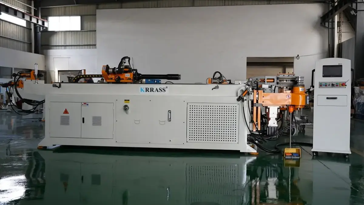
A tube bender machine for bending pipes can be categorized into CNC (Computer Numerical Control) and hydraulic. These machines find wide applications in various industries, such as electrical construction, railway and highway development, bridges, and shipbuilding.
Unlike sheet metal bending machines, tube bender machines are primarily used for bending steel pipes. They are commonly employed in electrical construction, railway construction, boiler manufacturing, bridge construction, shipbuilding, furniture decoration, and other pipe installation and construction applications.
Tube bender machines are considered essential equipment in the pipe machinery industry. They boast various functionalities, well-designed structures, and ease of operation.
What is a tube bender machine?
A tube bender machine is a machine used to bend pipes. It is typically used to turn hollow or solid lines made of rigid materials into various shapes, including angles and curves. This includes bending pipes such as iron, steel, aluminum alloy, etc.
Tube bender machines can be categorized into CNC and hydraulic tube bender machines. They find wide applications in power plants, highway and railway construction, boiler pipe installation and maintenance, bridge construction, shipbuilding, furniture decoration, and more.
Tube bender machines offer several advantages, including versatility, well-designed structures, and ease of operation.
Types of Tube Bender Machines
Tube bender machines are machines used to bend tubes into various shapes, such as I-beams, channel steel, angle steel, wire, and more. They can also create coils, "U" shaped semi-pipes and spiral pipes. The categories of tube bender machines include hydraulic electric tube benders, horizontal hydraulic tube benders, and multifunctional coil tube benders.
Electric tube benders derive power from electricity, motors, gearboxes, and chain drives. In contrast, hydraulic tube benders rely on hydraulic pressure to perform various bending operations, including clamping, bending, auxiliary forward and backward movement, feeding, and core retraction.
Hydraulic tube benders are commonly used flat-circle automatic bending machines with multifunctionality, well-designed structures, ease of operation, convenient mobility, and quick installation. They find wide applications in electrical construction, highway and railway construction, boiler manufacturing, bridge construction, shipbuilding, furniture decoration, and more.
On the other hand, CNC tube benders utilize servo motors instead of hydraulic power. They can control feed and retraction, angle rotation, tube bending and retraction, auxiliary forward and backward movement, and head lifting. CNC and hydraulic tube benders differ in continuous production, processing precision, and the three-dimensional forming of pipe fittings.
CNC tube benders can cause cold bend pipes with a single or double bending radius and are widely used in various industries, including automotive and air conditioning, for bending multiple pipe fittings and conductors.
Methods of Tube Bending
Tube bender machines use two bending methods:
- Cold bending includes hydraulic tube bending machines, electric tube bending machines, and three-roll tube bending machines.
- Hot bending, represented by the model known as the medium-frequency tube bending machine.
Working Principles of Tube Bender Machines
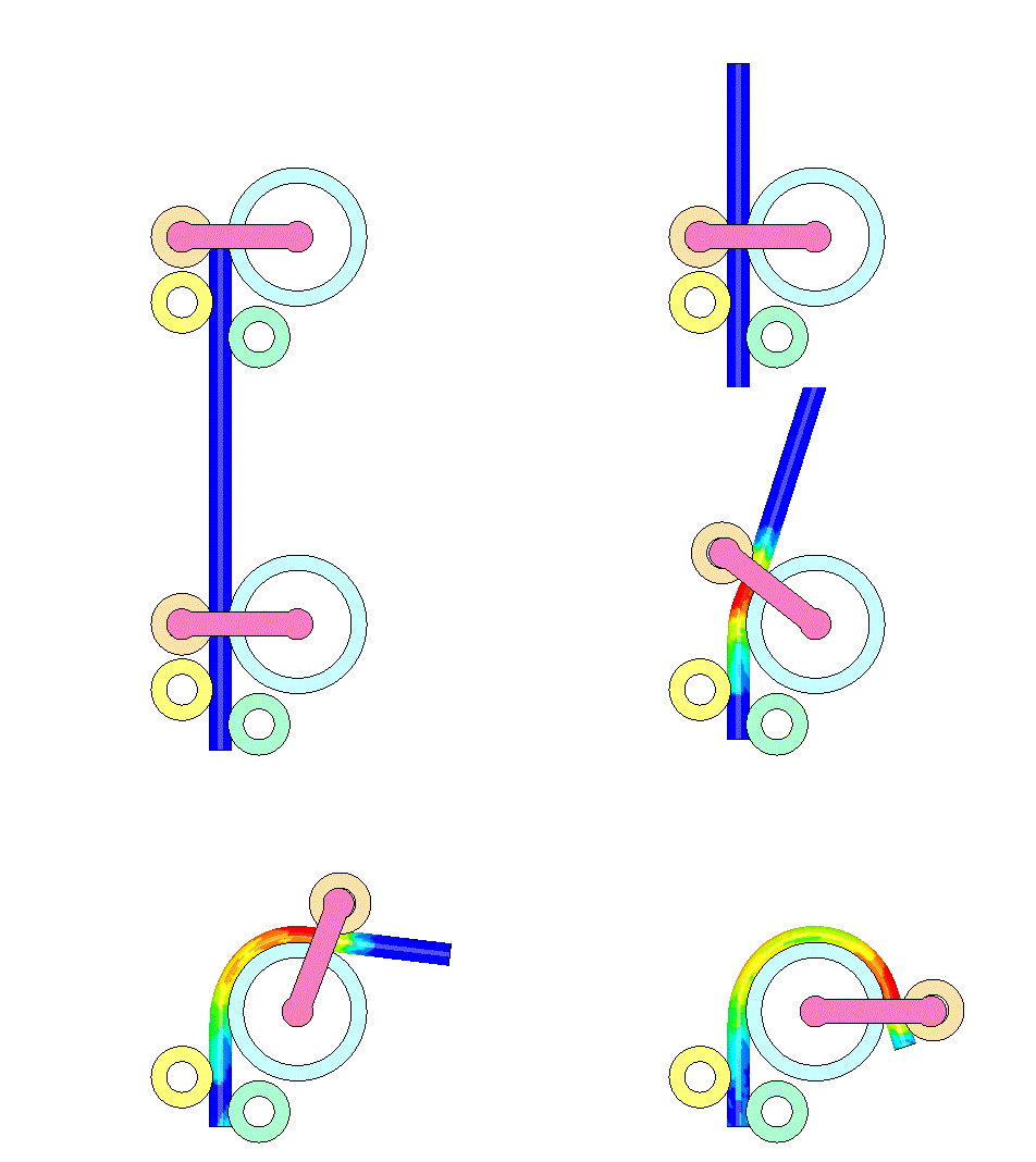
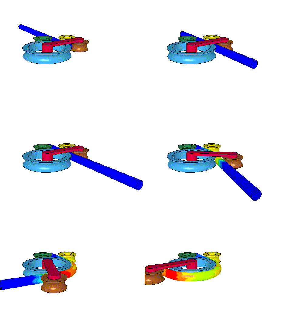
Tube bender machines can be categorized into different types based on their bending methods, including push bending, roll bending, compression bending, and ring bending. Among these techniques, ring bending stands out as it offers relative ease in automation, making it the preferred choice for most tube bender machines. Visual illustrations can facilitate an understanding of the bending process's principles, effectively depicting the various steps involved.
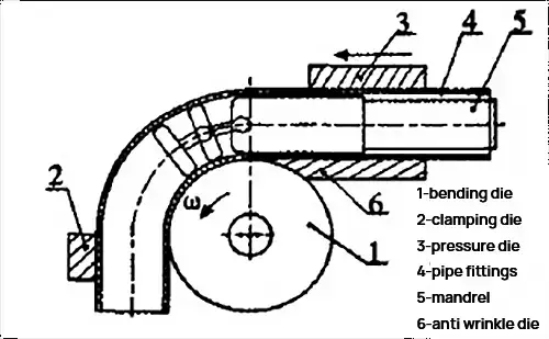
The bending process utilizes a mandrel, clamping dies, and pressure dies. The mandrel is mounted on the spindle, while the clamping dies are used to secure the workpiece, preventing axial movement. The force fails to consist of a guiding die and a following die. During bending, the guiding die applies appropriate pressure to the workpiece to prevent wrinkling while the next die moves along with the workpiece. A mandrel is also used to support the inner cavity of the workpiece, preventing wrinkling, flattening, thinning, or other deformations during bending.
The spindle rotates, causing the tube to wrap around the mandrel and form a curve. The process also involves feeding the workpiece, preparing the space for the next bend, etc. The radius of the mandrel determines the bending radius, and different bending radii can be achieved by replacing mandrels of different radii.
Structure and Working Principles of Automatic Tube Bending Machines and Electro-Hydraulic Tube Bending Machines:
The hydraulic system of a tube bending machine consists of an electric oil pump, high-pressure oil pipes, quick connectors, working cylinders, and plungers. The bending head of the device includes upper-pressure plates, lower-pressure plates, die heads, and rollers—the electric oil pump outputs high-pressure oil sent to the working cylinders through high-pressure oil pipes. The high-pressure oil drives the plungers in the working cylinders to generate thrust, thus achieving bending through the bending head.
Characteristics of a Tube Bender Machine
The tube bender machine features the following:
- Touchscreen control with the addition of a numerical control (NC) module, allowing for convenient program settings through a dialogue-based interface.
- It possesses a stable structure resistant to deformation, ensuring reliable performance.
- Each file can store up to 16 bending angles, and the machine's memory can store 16 sets of files, providing a wide range of bending options.
- The machine incorporates a slow-speed positioning function and maintains stable bending angles, guaranteeing a repeat accuracy of ±0.1°.
- In case of errors, the relevant information is displayed on the screen, assisting operators in promptly resolving issues.
- The equipment is equipped with development software, enabling the conversion of pipe processing values into coordinates and allowing for editing and calculations on a desktop computer, enhancing processing efficiency and flexibility.
Advantages and Disadvantages of Tube Bender Machines
When using a tube bender machine, high-pressure oil is delivered to the working cylinder through a high-pressure oil pipe from an electric oil pump. The high-pressure oil propels the plunger in the operating cylinder, generating the required force to bend the tube through the bending components.
Tube bender machines offer several advantages:
- They feature a touchscreen interface and numerical control (NC) module, allowing for easy and straightforward program settings through a dialogue-based operation.
- The machine's bed structure ensures stability and minimizes deformation.
- The mobile foot switch provides functions such as automatic start, emergency stop, and quick stop, ensuring high levels of safety.
- It offers the option for manual, semi-automatic, and full-cycle functions.
- The machine head and bending die design provides an elegant and optimal bending space.
- A large-capacity cooling circulation system ensures stable machine operation.
- The mold replacement process is convenient, allowing for flexible production.
During the processing, the movable controller's screen displays the bending die's current processing values, allowing for the setting of single-step, semi-cycle, and full-cycle operations.
Tube bender machines are primarily used for bending pipes and are commonly employed in road construction, automotive manufacturing, and shipbuilding industries.
Tube bender machines offer high stability, user-friendly operation and maintenance, low operational noise, improved safety, and environmental performance.
Components and Functions of a Tube Bender Machine
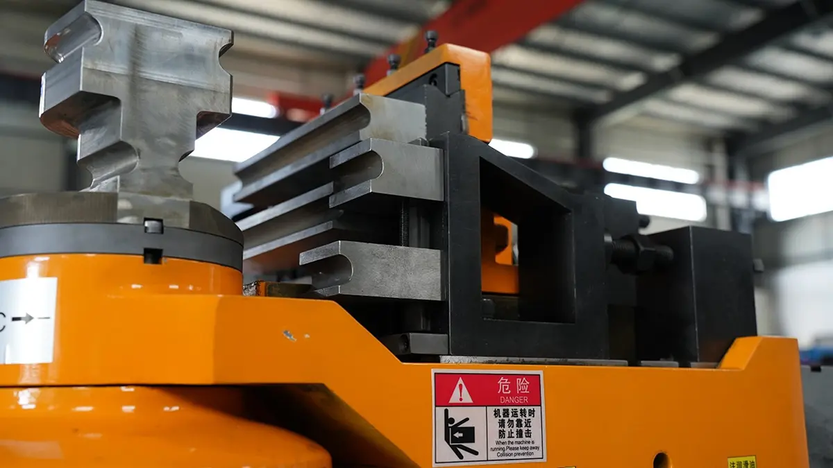
Tube bender machines are widely used daily, but many must familiarize themselves with their constituent parts. Let me now introduce the critical components of a tube bender machine.
1. Fully Automatic Bed:
The bed features a spindle frame welded with channel steel, and the upper and lower bearing support plates of the spindle are mounted on a 15mm thick steel plate frame.
2. System Components:
The hydraulic system components can utilize commercial parts or aviation hydraulic components.
3. Transmission Components:
The transmission components include oil cylinders, racks, gears, and shafts.
4. Die Components:
The die components, made of bearing steel or rolled steel, serve as supporting tools and undergo heat treatment to achieve a hardness of HRC48~52 based on the surface diameter.
5. Clamping Components:
The hydraulic clamping components include a slide plate, rocker arm, and hydraulic cylinder. The expansion and contraction of the hydraulic cylinder drive the movement of the rocker's arm.
6. Electrical Components.
Tube Bending Technology
Tube bending machines share similarities with sheet metal bending machines.
When a tube is subjected to pure bending due to external torque M, the outer wall of the neutral axis undergoes tensile stress σ1, causing it to thin out, while the inner wall experiences compressive stress σ1, resulting in thickening.
The cross-sectional shape of the pipe tends to become elliptical due to the combined forces of F1 and F2. Excessive deformation can lead to cracks on the outer wall and wrinkles on the inner wall.
The extent of pipe deformation is influenced by the relative bending radius (R/D) and the relative thickness (T/D). Smaller values of R/D and T/D result in greater degrees of deformation.
Ensuring the pipe's integrity throughout the forming process is of utmost importance, necessitating precise control over the extent of deformation within acceptable limits. The bending capacity of the line relies not solely on the material's mechanical properties and the bending technique employed but also on the specific demands placed upon the pipe.
Limitations in Tube Bender Forming
The forming limitations of pipe components should consider the following factors:
- The maximum extension of the transverse tensile deformation zone around the neutral axis should not exceed the material's plastic allowance to prevent fracture.
- Thin-walled structures experiencing tangential compressive stress in the internal deformation zone around the neutral axis should be within the instability threshold to avoid wrinkling.
- If the pipe component requires a specific degree of ovality, forming limitations need to be controlled to achieve the desired twist.
- Forming limitations should be regulated to prevent excessive wall thickness thinning if the pipe component has strength requirements to withstand internal pressure.
Tube Bender Machine Components
- The rocker's arm ensures that the bending radius of the pipe meets the specified requirements, while the clamping seat restricts the pipe's spring back during the bending process.
- The pump station is divided into high-pressure and low-pressure sections, providing power for the operation of guide wheels, clamping seats, oil cylinders, pushing devices, carriage plates, and straightening wheels.
- The guide wheel device comprises two guide wheels, a support frame, and a clamping drive system. The opening and closing of the guide wheels are driven by hydraulic pressure, aiming to ensure horizontal bending of the steel pipe under the interaction of the rocker's arm.
- The driving device serves as the power source for the pushing device.
- The straightening wheel prevents vertical deformation during bending. At the same time, the use of a floating anti-ovality fixture ensures that the ovality of the steel pipe after bending meets the specified requirements.
- The pushing device, composed of a carriage plate, bed frame, transmission shaft, and traction chain, advances the steel pipe forward, enabling its bending under the action of the rocker arm and guide wheels.
Tube Bender Machine Structure
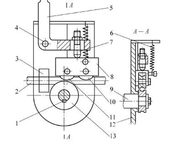
Key Components:
- Steel Pipe
- Steel Pipe Clamp
- Pivot Shaft
- Handle
- Spring
- Adjustment Screw
- Roller Seat
- Spindle
- Guiding Pulley
- Rollers
- Turntable
- Bending Module
(1) Bending
Installation:
Unscrew the bending fixing nut counterclockwise.
Insert the steel pipe and tighten the bending fixing nut.
(2) Clamp Tooling
Installation:
Pull out the clamp tooling to secure the center shaft.
Insert the clamp tooling and then insert the fixed core shaft.
Adjustment:
A. Secure and release the clamping seat, then switch the control panel to manual mode. Press the clamp button until it reaches the end of the clamping stroke (ensuring a gap between the clamp toolings, which can be adjusted using the clamp seat adjustment screw).
B. Adjust the clamp seat adjustment screw to ensure a complete seal between the clamp tooling and the steel pipe.
C. Press the reverse button to retract the clamp tooling, then adjust the clamp screw by rotating it clockwise about 1/2 to 1/4 turn.
D. Finally, tighten the locking nut on the clamping seat.
(3) Press Tooling
Installation:
A. Remove the fixing screw from the press tooling and then insert the press tooling.
B. Secure the guiding mold screw.
Adjustment:
A. Secure and release the clamping seat, then switch the control panel to manual mode. Press the clamp button until it reaches the end of the clamping stroke (there should be a gap between the clamp toolings that can be adjusted using the clamp seat adjustment screw).
B. Adjust the clamp seat adjustment screw to ensure a complete seal between the clamp tooling and the steel pipe.
C. Press the reverse button to retract the clamp tooling, then adjust the clamp screw by rotating it clockwise about 1/2 to 1/4 turn.
D. Finally, securely tighten the locking nut on the clamping seat.
(4) Core Shaft
Installation:
A. Insert the core shaft into the mandrel in a clockwise direction.
B. Then secure the screw of the core shaft.
(Note: The core shaft must be installed facing the bending direction.)
Standardization of Tube Bending Types
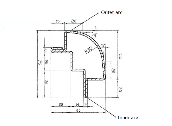
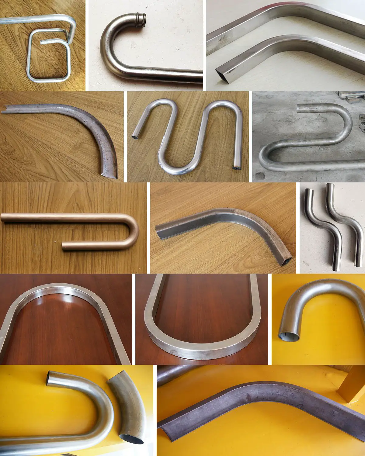
When designing exhaust pipes, it is essential to avoid using large-radius arcs, arbitrary curves, and compound bends, especially arcs exceeding 180°.
Large-radius arcs increase the workload and are limited by the size constraints of the tube bending machine.
Unreasonable designs involving arbitrary curves and compound bends hinder mechanization and automation, making it easier for operators to escape labor-intensive manual work.
Bends with a radius greater than 180° pose challenges for tube bending machines in achieving the desired output.
Tube Bending Machine Bending Speed
The bending speed significantly affects the quality of the forming process. The primary considerations are as follows:
- If the speed is fast enough, it can result in flattened areas and adequate roundness, leading to pipe cracking and failure.
- If the speed is too slow, it can cause wrinkling and slippage of the pressure blocks, particularly in larger-diameter pipes, resulting in pipe deformation at the bending location.
When establishing the maximum bending speed for the machine, it is advisable to set the final bending speed within 20-40% of its total capacity.
Standardization of Tube Bending Radii
Choosing appropriate bending radii is crucial to achieve consistency in both "one tube per die" and "multiple tubes per die" scenarios.
- In cases where a pipe has only a few bending locations or angles, and the die modules of the tube bending machine cannot be changed during the bending process, only one bending radius can be used, known as "one tube per die."
- However, when employing the "multiple tubes per die" approach, pipes with the same diameter should utilize the exact bending radius, and the same die modules should be used to bend different shapes of tubes. This approach helps reduce the number of required die modules.
Tube Bending Mandrel and Its Position
The mandrel supports the pipe's inner wall during bending, ensuring the desired bending radius and preventing deformation. The presence of the mandrel is vital for maintaining the quality of the bent tube.
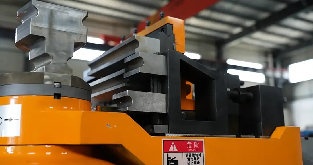
Various mandrels are available, including cylindrical, universal single-head, double-head, triple-head, and four-ball mandrels, and positioning single-ball and multi-ball mandrels.
The position of the mandrel during the pipe-forming process has a significant impact. In theory, the tangent of the mandrel should be at the same level as the tangent of the bending dies. However, extensive experiments have shown that advancing the mandrel forward by 1-2 millimeters yields better results, resulting in optimal bending quality.
Of course, excessive movement of the mandrel can lead to the formation of a "gooseneck" on the outer wall of the bending area.
Installation and Adjustment of Tube Bending Tooling
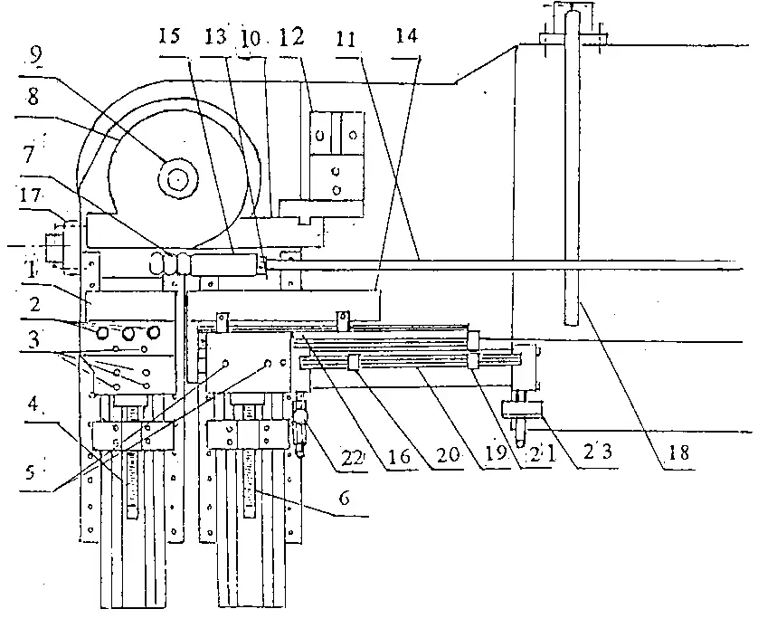
- Clamp Die
- Clamp Die Pivot Shaft
- Clamp Die Seat Fixing Screw
- Clamp Die Adjustment Screw
- Pressure Die Sleeve Fixing Screw
- Pressure Die Sleeve Adjustment Screw
- Mandrel Ball
- Bending Die
- Bending Die Locking Nut
- Anti-Wrinkle Plate
- Mandrel Rod
- Anti-Wrinkle Plate Seat
- Mandrel Rod Fixing Nut
- Guide Die
- Mandrel
- Guide Die Seat
- Material Stop Bar Seat
- Material Support Bar
- Auxiliary Push Limit Sliding Plate
- Auxiliary Push Front Limit
- Auxiliary Push Rear Limit
- Auxiliary Push Speed Control Valve
- Auxiliary Push Pressure Gauge
Please note that the above information describes the components related to installing and adjusting tube bending tooling.
Installation of Fully Automatic CNC Tube Bending Machine Tooling (Refer to the diagram)
Bending Die Installation
Clockwise, tighten the bending die locking nut (9) until it is secure. Loosen and remove the nut, replace it with the required bending die, and pull the locking nut.
Main Clamp Die Installation
Remove the main clamp die pivot shaft (2) and replace it with the desired clamp die. Insert the pivot shaft. Loosen the clamp die seat fixing bolt (3) and manually operate the main clamp to engage the clamp to die with the bending die. Rotate the clamp die adjustment screw (4) forward until the clamp dies firmly holds the bending die. Then, release the main clamp and rotate the clamp die adjustment screw by 1/3 to 1/2 turn. Finally, tighten the clamp die seat fixing screw.
Guide Clamp Die Installation
Install the guide die using the same method as above. However, adjust the clamping force to be slightly looser than the main clamp die. If there are wrinkles inside the tube, move the pressure die sleeve adjustment screw forward by approximately 1/4 turn and continue test bending until the wrinkles are eliminated. Pay special attention to synchronizing the extra push-forward speed with the bending rate during the test bend.
Mandrel Rod and Mandrel Cylinder Seat Installation and Adjustment
Install the mandrel ball (7) on the mandrel rod (11). Screw the mandrel rod into the mandrel (15). Connect the mandrel to the cross joint of the mandrel cylinder. The adjustment typically involves extending the front end of the mandrel rod by 2-5mm beyond the center cutting point of the bending die (the distance depends on the diameter of the bending die; a larger diameter requires a slightly longer length). Install the mandrel cylinder seat on the guide rail of the mandrel cylinder. The guide rail is equipped with a scale, where the measurement displayed corresponds to the radius size of the bending die. Consequently, the mandrel cylinder seat should be adjusted to align with the new die size when replacing the bending die.
Anti-Wrinkle Device Installation
Fix the anti-wrinkle plate (10) onto the anti-wrinkle seat (12). Ensure the curvature of the anti-wrinkle plate fits tightly against the bending die (8), with the front end reaching as close to the center of the die as possible. The parallelism between the rear end of the anti-wrinkle plate and the guide should differ by 1-2 degrees to minimize friction between the anti-wrinkle plate and the workpiece.
Transportation and Installation of Tube Bending Machine
1. Transportation
The entire machine can be lifted using steel wires passed through the bottom of the device. Cotton or fabric should be placed between the steel wire and the machine's contact areas to prevent damage to the machine's surface. Securing the movable parts during transportation is essential to avoid sliding or collisions.
2. Installation
The machine can be directly placed on the floor, and the equipment can be leveled by adjusting the leveling pads under the machine's feet. The positioning of the oil cooler relative to the device can be determined based on actual operational requirements.
3. Preparations for Testing
1) Before starting the machine, the operator should read the instruction manual to familiarize themselves with safety precautions, machine performance, and operating procedures.
2) Connect the cables between the control panel and the main machine.
3) Fill the hydraulic oil tank with hydraulic oil up to the midpoint of the oil level gauge.
4) Fill the rotary body and gearbox with No. 20 mechanical oil up to the midpoint of the oil level gauge.
5) Apply lubricating grease to the linear guide slide block and lubrication cups at various points.
6) Check for foreign objects on and around the moving parts' trajectories.
7) After connecting the power supply, press the hydraulic motor start button (MOTOR) and quickly press the emergency stop button (FSTOP) while observing if the motor rotation aligns with the direction indicator. If it does not match, adjust the power supply wiring and try again.
8) Check the hydraulic system pressure (after starting the hydraulic motor, use a suitable tool to actuate the solenoid relief valve core). The pressure indicated on the pressure gauge should be less than 14 MPa (generally set correctly during factory calibration).
Applications of Tube Bending Machines
1. Applications in the Power Generation Equipment Manufacturing Industry
The demand for power generation equipment is increasingly evident due to the global scarcity of resources and rising oil prices. Tube bending machines play a significant role in the manufacturing process of power generation equipment. The cost involved in using CNC tube bending machines is substantial.
2. Applications in the Mold Manufacturing Industry
Tube bending machine tools are used in various stages of mold manufacturing, including forming molds, hot molds, cold molds, plastic molds, and more. The primary users of CNC tube bending machines in this industry include the automotive, train, general machinery, and furniture manufacturing sectors.
3. Applications in the Aerospace Industry
Tube-bending machines are commonly used in aerospace to turn aircraft structural components. These components are typically significant in size and have traditionally been made of aluminum alloys. However, with the increasing use of titanium alloys and composite materials, the demand for CNC tube bending machines with higher precision and efficiency is also growing.
What is the price of a tube bending machine?
The configuration of a hydraulic tube bending machine plays a crucial role in determining its price. There is a saying that price equals the product. Each price has its reasons and requirements. Users who prioritize quality for hydraulic tube bending machines, requiring high bending accuracy and efficiency, consider the internal configuration of the equipment as a determining factor. Some customers place importance on price while still having specific quality requirements. Balancing these factors can be challenging. The current market prices for tube bending machines range from 30,000 to 1 million RMB, depending on material thickness and turning radius requirements.
Tube Bending Machine Adjustments and Operations
1. Machine Adjustments
Select the appropriate tooling based on the pipe's outer diameter, wall thickness, and bending radius to achieve the desired geometric shape for bending pipes. Then, adjust the corresponding components as follows:
- Bending Angle: Input the desired angle on the operation screen according to user requirements (refer to the electrical manual).
- Clamping and Assist Sliding Mechanism Adjustment: The clamping and assist mechanisms use a linkage force-boosting structure. To ensure self-locking in the connected state, loosen the screw of the clamping and help the mechanisms' lead screw. In manual mode, position both agents in the clamping position, then tighten the lead screw. The one-way throttle valve can regulate the sliding block's speed, ensuring synchronization with the main spindle.
- Adjust the transverse shifting lead screw of the rotating part to align its centerline with the center of the bending section of the tooling based on the selected pipe material and tooling.
- Tailstock Adjustment: Align the center of the mandrel with the center of the bending area of the tooling, then adjust the lead screw on the tailstock piston rod to extend the mandrel to the appropriate position.
2. Machine Dry Run
- In manual mode, press the action buttons to drive the corresponding cylinders and observe if the movements are regular. There should be no creeping, pulsation, or oil leakage.
- Use the jog function to move the carriage along the guide rail and rotate the rotating sleeve to observe its flexibility and accuracy.
- Drive the clamping cylinder of the chuck to monitor the sleeve's movement and the clamping's reliability.
- Select several different angles and observe the coordination and continuity of the activities in automatic mode. Once all these aspects are typical, the machine can be put into regular operation.
Tube Bending Machine Operation Tips
After purchasing a tube bending machine, consider the following points:
- Before the operation, check if all lubrication points are adequately oiled, the safety devices are reliable, and the moving mechanisms are secure. Only proceed with the process after one person has confirmed these conditions.
- Activate the bending head pump and verify if the system pressure falls within the designated range. Excessive force can damage hydraulic components and energy wastage, while inadequate stress can affect the machine's performance.
- Adjust the positions and angles of the members to position the workpiece to the desired length.
- Adjust the vertical lifting guide rail to clamp the iron pipe with the pressure die cylinder.
- Ensure that the die clamping cylinder can firmly hold the iron pipe.
- During regular operation, place the workpiece into the bending die with the front end in contact with the positioning point. Step on the foot pedal switch to complete the bending process.
- After completing the work, cut off the power supply and perform appropriate cleaning and lubrication.
- In an emergency during operation, press the emergency stop button, switch the rotary switch to the manual position, and manually reset. If a malfunction occurs, report it for timely repair.
Daily Maintenance and Precautions for Tube Bending Machine
- the machine should be regularly maintained by trained and qualified personnel.
- Check if the pressure of each hydraulic system is standard.
- The oil pipes of the bending arm should not touch the ground.
- Regularly check the hydraulic oil level in the tank, which should be maintained at 80% or above.
- The temperature of the oil level indicator should not exceed 60°C.
- Apply lubricating grease regularly to the gear and rack engagement area.
- Lubricating grease should be added regularly to sliding and rotating parts.
- When operating below 5°C, prevent water from freezing.
- Do not strike or place magnetic objects near the servo motor.
- When cleaning the LCD, disconnect the power first and avoid using liquid cleansers or liquefied gas.
- Do not place the machine in areas exposed to rain or moisture.
Maintenance of Tube Bending Machine
Here are eight methods for maintaining the tube bending machine:
Method 1:
Strictly follow the operating procedures and guidelines when operating the tube bending machine.
Regular maintenance of the machine is necessary, and maintenance personnel must receive proper education and training.
Method 2:
Keep the tube bending machine clean, and apply rust preventive oil to unpainted areas.
Check if the pressure of each hydraulic system is standard.
Method 3:
Before each start-up, add lubricating oil at specified points and in the required quantity according to the lubrication chart.
The oil must be clean and free from sediment.
Ensure that the oil pipes of the bending arm do not touch the ground.
Method 4:
Regularly inspect and maintain switches, fuses, and handles to ensure reliable operation.
Regularly check the hydraulic oil level in the tank, which should be at least 80% of the oil level gauge.
Method 5:
Regularly replace and replenish the lubricating oil in the motor bearings and monitor the motor's performance.
The temperature indicator of the oil level gauge should not exceed 60°C.
Method 6:
Regularly inspect the condition of the V-belts, handles, knobs, and keys. Replace them promptly if heavily worn.
Periodically lubricate the gear and rack engagement area with lubricating grease.
Method 7:
Non-designated personnel should refrain from operating the equipment. Generally, people should stay away from the machine and keep it stationary.
Sliding and rotating parts must be regularly lubricated.
Method 8:
Before starting work each day, Perform lubrication and clean the tube bending machine for 10 minutes.
When operating below five °C, avoid water accumulation to prevent freezing.
Avoid placing magnetic objects near the servo motor or striking it.
When cleaning the LCD, disconnect the power first, and avoid using liquid cleansers or liquefied gas.
Do not place the machine in areas exposed to rain or moisture.
Common Malfunctions of Tube Bending Machines and Troubleshooting Methods
If oil leakage is detected in the cylinder, it is necessary to replace the sealing ring.
If the machine has insufficient pressure, check if the oil level in the tank is sufficient and if the oil temperature is too high.
The display screen will show the corresponding fault reason when the proximity switch is undetected. Identify the problem based on the displayed fault information and perform maintenance and troubleshooting.
If the angle is inaccurate, check if the jaw cylinder is fully positioned or if the jaw oil pressure is too high.
If the servo does not rotate or the servo motor fails to feed during operation, examine the servo drive for fault codes. The most frequent issue encountered is a momentary low voltage condition. If you experience this situation, turn off the main power supply, wait for 30 seconds, and restart the machine. If the problem persists, please notify the company. Please do not attempt to disassemble or repair it; you will be responsible for the consequences.
If the bending angle is incorrect, check if the fixing screws of the encoder coupling are loose and if there is an input angle for slow bending.
If there is no response to any action in the hydraulic system, check if the corresponding solenoid valve is abnormal.
How to Choose the Right Tube Bending Machine?
First, the range of pipe diameters for the bending head must be determined based on actual production needs.
Tube bending machines are utilized in metal processing factories for various fittings. Still, it is essential to note that each device has limitations, and its specific parameters determine its bending capacity.
Next, it is necessary to determine the bending parameters of the most extensive fitting within the bending range, including:
- Material of the fitting (steel pipe, stainless steel pipe, aluminum pipe, etc.)
- Type of pipe (a round tube, square pipe, angle iron, etc.)
- Tube outer diameter
- Tube wall thickness
- Bending radius (referring to the pipe's inner diameter) and other relevant parameters.
Finally, provide these parameters to the manufacturer. They will usually recommend the model you need based on your parameters.


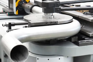

I find it interesting when you said that high-pressure oil is delivered to the working cylinder of the machine used by tube bending services through the pipes to the electric oil pump. I can’t imagine how those types of machines are important in order for you to achieve the outcomes you want for your project. And having the right tools and people will also give you the assurance that you are providing the best outcome when you are catering to the requests of your clients.