Click the button to select the Part you want to view:
Thank you for choosing our products!This manual makes a detail introduction about the use of BM111 series auto-focusing lase rcutting heads, including installation, operation and maintenance instructions etc. If you have otherthings need to know, please contact us directly.Please read the manual carefully before using the series cutting heads. This will help you use itbetter.Due to the continuous updating of product features, please note the product you havereceived may differ in some aspects from the illustrations in this manual. We apologize for theinconvenience to you.
Chapter 1 - Introduction
This manual includes the general description, basic installation, factory settings, operation andmaintenance services and other aspects of BM111 series products, which have too many opticaland mechanical customization configurations, so only the main parts will be introduced in thismanual.The BM111 series laser heads are auto-focusing cutting heads for fiber laser, which arereleased by Switzerland RAYTOOLS AG in 2017.
The products are equipped with internal servomotor drive units, which use the linear mechanism to drive the focusing lens to change position inthe range of about 22mm automatically. Users can use the program settings to achieve continuousadjustment of the focus position to complete the rapid perforation of thick plates and automaticcutting of different thickness, material plates. The products can be equipped with D30 compositelens groups to integrate the beam. Diversified interface configurations can be adapted to a varietyof fiber lasers, optimized optical and water-cooled design allows the laser heads work under highpower for a long time continuously and steadily.
1.1 Product Features
- Optimized optical configuration and smooth and efficient airflow design;
- Automatic focusing range + 10 ~ -12mm, adjustment accuracy 0.05mm;
- Equipped with D30 composite lens groups, the maximum fiber power is up to 3KW;
- Maximum acceleration of focus lens driver 10m / s
- The drawer-type of lens mount makes the replacement of protective lens more quickly andeasier;
- The composite lens groups are used for beam collimating and focusing to obtain the bestoptical quality and cutting effect;
- Equipped with QBH, QD and other fiber interfaces can match with various fiber lasers.
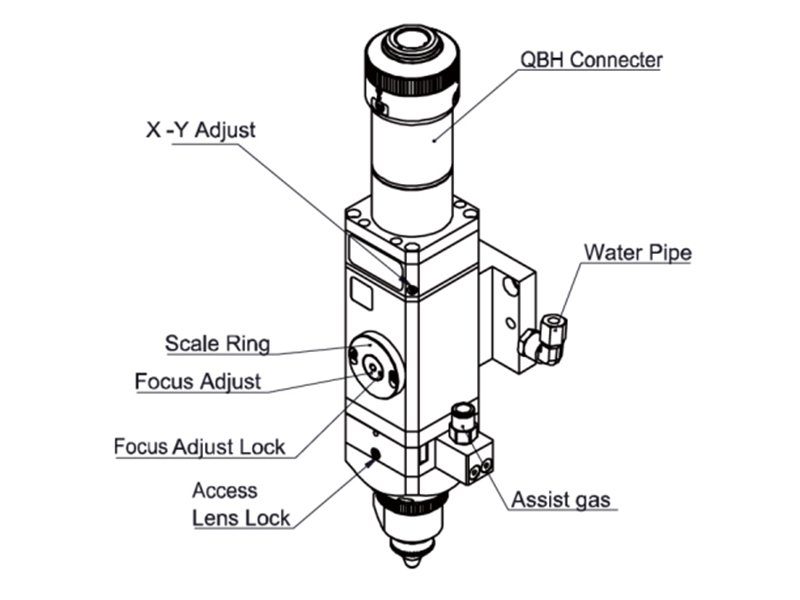
1.2 Structure & Function
As shown in Figure 1, the laser head consists of four basic units, such as collimating module,focusing driver module, protective lens module and nozzle module.
- Collimating module: Can collimate the incident laser into a parallel beam and adjust the beamspot from the center of the nozzle
- Focusing driver module: The collimating beam is focused into a small beam spot which has highpower density, and the focus position is adjusted by the driving device automatically;
- Protective lens module: The protective lens protects the focusing lens from damage by thereturning slag and prolongs the service life of the focusing lens;
- Nozzle module: Guide the focus beam to the work piece and produce high velocity jet cutting toachieve high quality cutting.

Chapter 2 - Product Configuration
2.1 Configuration Type
[wptm id=44]
2.2 Configuration
[wptm id=45]
Note: The above form is only for standard factory configuration.

2.3 Cutting Head Shape
2.4 Cutting Head Configuration Diagram
2.4.1Interface Type

2.4.2Focus length

[wptm id=46]
Chapter 3 - Mechanical Installation
3.1 Mounting Holes
The mounting holes size and position of the BM111 laser cutting head are shown in Figure 3.1,which can be used to fix the laser head and machine tool. We strongly recommend customers toinstall the laser head perpendicular to the process material surface as requested and make sure thelaser head is locked, this is one of the preconditions to ensure the follow-up stable cutting effect.

Note:The Z-axis motor slide plate for fixing the laser cutting head should be connected withmachine tools and make sure there is a good grounding.
3.2 Connection of Water Pipe and Gas Pipe
3.2.1Water-cooled interface
BM111 laser cutting head has 2 sets of water-cooled channels, the direction of water entry andexit can be arranged arbitrarily. It is important to note that when the laser power is greater than 500watt, we recommend users to use water-cooled. As you can see from Figure 3.2, the position andquantity of the water interfaces, and the table below details the recommended water flow rate.The design of this water-cooled interface is closed loop water-cooled system, and it also can be used equipped with external water supplied, the precondition is to meet the requirements in the list.

[wptm id=47]
3.2.2 Assist gas interface
The impurities in cutting gas such as hydrocarbons and water vapor can damage the lens and cause laser power fluctuation as well as inconsistencies between the sections of the work piece.The following table is the recommended cutting gas specifications.
The higher the purity of the gas,the better the quality of the cutting section.Impurities can be filtered out in gas supply tube, but Oxygen and water vapor can permeatelight path through non-metallic materials, which is the source of the appearance of dust andhydrocarbons. Stainless steel fittings are recommended, at the same time customers must use filters which can remove a minimum of 0.01 micron particle to purify.
We recommend customers to use the pressure gauges with stainless steel diaphragm.Industrial pressure gauges suck in air. Rubber diaphragm produces hydrocarbons by aging or otherfactors.About the nozzle cooling gas, Nitrogen or finely filtered air is recommended. The pressureshould be less than 10 bar. Do not use oxygen as a cooling gas.
[wptm id=48]Note:Gas interfaces can not be replaced arbitrarily, especially do not use PTFE TAPE.Otherwise, the gas path will be blocked, the normal cutting will not be possible and thelaser head parts will be damaged at the same time.
3.3 Connection of Cutting Head Cable
3.3.1Connection of Cutting Head and Cable
Connect the corresponding connector of cutting head with motor power cable, encoder cable,sensor cable respectively (as shown in figure 3.3). After the proper length is reserved, the cable isinserted into the track groove of the machine tool and fixed.

3.3.2Connection of Cable and Driver
Connect motor power cable and signal cable with the corresponding interfaces of driveraccording to the definition in cable sleeve.(Note: The low level output of the limiting sensor isnormally closed output mode.)
Note:All wiring is in the state of power-off, and the power can be debugged afterinspection.
3.4 Fiber Input Interface
BM111 is suitable for most industrial fiber lasers. It is equipped with collimating lens assembly.The connection between the end of the fiber and the cutting head is called fiber interface.Commonly used fiber connectors include QBH, QD and so on, and every fiber interface has itsunique fixation method. Please refer to corresponding instruction of fiber interface. Figure 5 showsthe installation interface of QBH connector.
Note:The optical devices must be kept clean and all dust must be removed before use. Ifthe optical fiber is vertically inserted in the laser head, the laser head must be rotated 90degrees to the horizontal level and then inserted the optical fiber in it to prevent dustfrom entering the interface and falling on the surface of the lens. Insert the optical fiber beforefixing the laser head.
3.5 Fiber Insertion and Interface Direction Adjustment
In this section, an optical fiber insertion method is described in conjunction with QBHconnector.First, align the red point at the end of the QBH connector with the red point of the handwheel;then remove QBH dust proof cover ,the red mark of fiber output end is aligned to QBH redmark ,insert the fiber interface straight to bottom; Then turn the QBH handwheel clockwise. It is inplace when you hear the "Da" sound, then pull the handwheel up and turn clockwise again.
When the fiber interface insert into the QBH connector, the red point on fiber is too far awayfrom the red point on laser head interface, causing an out of alignment insertion, users can refer tothese steps below to adjust the position of fiber interface on laser head for solving the problem. Asshown in Fig. 3.4, loosen the 4 locking screws of the part with a wrench, rotate the QBH interface ,then tighten the locking screws after the red mark is in place.

Learn more:
Learn more about our products, please visit and subscribe to our Youtube channel


