Click the button to select the Part you want to view:
Chapter 4 - ETC_F100 Installation
4.1 Interface and Signal
Interface
[wptm id=49]
SignalPin signals of the CON1 Interface:
[wptm id=50]
Pin signals of the CON2 Interface:
[wptm id=51]
Note:"N / A" is an interface without definition, please leave it blank
Pin signals of the CON4 Interface:
[wptm id=52]
Note:"N / A" is an interface without definition, please leave it blank.The above table shows the ETC-F100 controller only for factory default settings.To adapt the external circuit, there is a jumper cap inside the ETC_F100 to select the active-lowor active-high input signal. The output signal is selected active low or active high. To change thesignal level, contact us to change it.
4.2 Wiring


4.3 ETC_F100 Dimensions

Chapter 5 - Adjustment of Beam Center and Focus Position
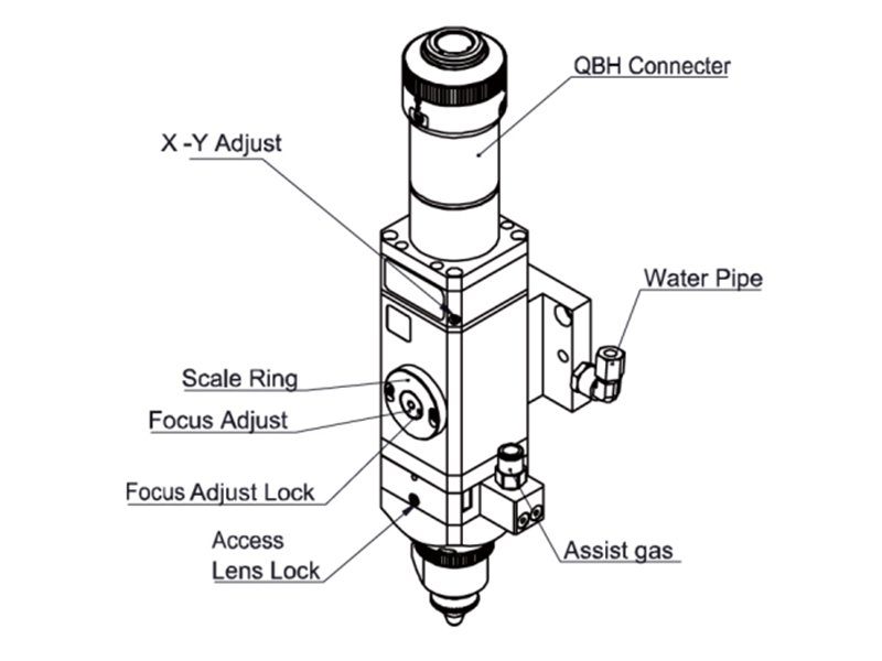
5.1 Beam Center Position Adjustment (QBH interface)
Cutting quality in a great extent depends on whether the beam spot is in the center of nozzleor not. If the beam spot is not in the center, the laser beam may hit the nozzle or inner wall of thelaser head, that leads to produce high temperature deformation. Beam center position adjustmentshould be considered when nozzle is replaced or the cutting quality is decreased.
Beam center position adjustment of the laser cutting head can be finished by adjustingCollimating lens, X-Y direction. The adjusting screws are located on the top of the cutting head asshown in Figure 5.1. By using inner hexagon spanner users can loosen or tighten the adjusting screwuntil the beam spot is located in the center of nozzle. Make sure the laser beam output from thecenter of nozzle. A method commonly used, tape dotting method:
- Pick a scotch tape, flatten it, and stick it to the nozzle end face.
- Open the inner guiding red light of the laser. Finding and observing the position that thered light on the scotch tape relative to nozzle center;
- Open and adjust laser generator at the range of 80W-100W ,then laser dotting.
- Tear off the tape and check the hole is in the center of the nozzle or not;
- Repeat the above steps until the beam spot is in the center of the nozzle .This center adjustment requires a series of steps, which is the basic operation of generallaser adjustment.

5.2 Beam Focus position Adjustment
Even BM111 is equipped with automated focusing system, it still need dot manually tore-determine the focus position when users replace the lens or lasers. For details about operatingsystem parameters, please refer to the system instructions.
Manual dotting can refer to the following steps:
- The laser head scale is displayed to the maximum, and the laser power range is set to80-100w;
- Then, within each moving 0.5mm (as small as possible), activate the laser to make a hole inthe textured paper;
- Dotting several times, finally compare and find out the scale corresponding to the smallesthole, which is the zero focus position, that is, the focus spot is just at the end of the nozzle end face.
Chapter 6 - Maintenance
6.1 Cleaning Lens
It's necessary to maintain lens regularly because of the characteristic of laser cutting process.Once a weak cleaning the protective lens is recommended. The collimating lens and focusing lensneed to be cleaned once every 2~3 month. In order to facilitate the maintenance of the protectivelens, the protective lens mount adopts a drawer type structure.(Fig6.1)

Lens cleaningTools: Dust-proof gloves or finger sleeves, polyester fibers cotton stick, ethanol, rubber gasblowing.Cleaning instruction:
- The left thumb and forefinger wear the finger sleeves;
- Spray ethanol onto the polyester fibers cotton stick;
- Hold the slide edge of the lens with left thumb and forefinger gently.(note: avoid thefingertip touching the surface of the lens)
- Put the lens in front of eyes, hold the polyester fibers cotton stick with the right hand. Wipethe lens gently in single direction, from bottom to top or from left to right, ( Should not be able towipe back and forth, to avoid secondary lens pollution)and use rubber gas blowing to sway thesurface of the lens. Both sides should be cleaned. After cleaning, make sure that there are noresidues: detergent, absorbent cotton, foreign matter and impurities.
6.2 Removal and Installation of Lens
The whole process need to be completed in a clean place. Wear dust-proof gloves or fingersleeves when removing or installing the lenses.
6.2.1Removal and Installation of Protective Lens
- The protective lens is a fragile part and needs to be replaced after damage.
- As shown in Figure 6.1, loosen two locking screws, hold the two sides of the drawer typelens mount and pull out the protective lens mount.
- Remove the pressure ring of the protective lens, remove the lens after wearing fingersleeves.
- Clean the lens, lens mount and sealing ring. The elastic sealing ring should be replaced ifdamaged.
- Install the new cleaned lens (Regardless of the front or back side) into the drawer type lensmount.
- Put the pressure ring of the protective lens back.
- Insert the protective lens mount back to the laser cutting head and tighten the lockingscrews.

Note:Do not directly pull the edge of the elastic sealing ring out so that it is easy todamage.
6.2.2 Removal and Installation of Collimating Lens
- The procedures for removing and installing collimating lens are as follows.
- Remove the laser head and move to a clean place. Clean all dust on the laser head surface.
- Use a 3mm inner hexagon spanner loosen the screws of collimating components( asshown in figure 6.3), and seal the part(connected to collimating components) with CrepePaper to prevent dust from falling inside the laser head.
- Unscrew the collimating lens mount and remove the spring pressure ring and thecollimating lens with the lens removing tool;
- Clean or replace the collimating lens.
- As shown in figure 6.4, reassemble the collimating lens components in sequence.
- Note that the spring pressure ring is tightened properly and re-screwed into the collimating component.
- Tighten the locking screws of collimating component.
- Check the focus position is at the center of the nozzle or not before using, if not , theposition should be reset.

6.4 Fault Analysis of ETC_F100
6.4.1Alarm Information
ETC-F100 may generate the following alarm information:
1.Upper and lower limit alarm
This alarm is generated when the system detects a sensor signal of the Z-axis upper limit orlower limit. If not meet the requirements, please reset the sensor position. If this alarm is alwaysdisplayed, check:
- Limit signal is not connected to the ETC-F100;
- Limit the sensor is obscured by unknown objects;
- Limit sensor installed improperly (this possibility is extremely small);
- The limit signal is disturbed. At this time, the corresponding limit signal may flicker in thefunction test, especially after the motor is enabled.
The ETC-F100 and the 24VDC limit signal can be independently powered A power filter is needed for the 220V AC of the Servo driver,and to ensure that the ground wire grounding well.
2."Zero returning"Alarm
After the system is powered off and restarted, the controller needs to go back to zero toestablish a reference coordinate system. If there is no back to zero, the panel will prompt " Zeroreturning ",It can be solved by the following methods:
- Perform a zero return operation through the ETC-F100.
- Select "Yes" and save it in the "power-on Reset" , and it will automatically return to zeroafter power-on again.
- High level can be input through "Zero returning" interface to realize backing to zero.
3."Exceeding z-axis stroke"Alarm
This alarm is generated when the actual Z-axis coordinate exceeds the Z-axis travel. When this alarm occurs, please note:
- Z-axis travel setting is appropriate;
- Whether the location of dial overtravel.
4."Servo Alarm
"Under normal circumstances, when the drive alarm, "Servo Alarm"will be displayed byETC-F100. If the drive is normal, and the ETC-F100 displays the "Servo Alarm" , it may be caused by the following conditions:
- Servo driver wiring is incorrect;
- External interference.
6.4.2 Common Problems Analysis
1."Servo Calibration" process terminated abnormally
- dial in the upper limit
When the dial is in the upper limit position, this error occurs when servo calibration isperformed. - dial position near the upper limit
The dial position near the upper limit (about 1mm), this error will occur in servo calibration.In this condition, please move the dial to the middle of the stroke (more than 1mm), and thentake the servo calibration.
2. The screen is abnormal displayed
The external interference may cause the screen to display abnormally, please reboot theETC-F100 when this abnormality occurs.
3. Z-axis coordinate offset
Under the static state, the Z axis coordinate keeps changing slowly, in this condition, the servocalibration can be restarted.
4. Input signal jitter or invalid
If the input signal is Jittering or invalid, enter the I / O port detection interface of the functiontest, directly connect 24V (active high) or 0V (active low) of the 24V DC power supply to thecorresponding input port, and observe whether the corresponding number is inverted :For high effective input signal, 24V can be directly connected to the corresponding input port if the corresponding number is inverted, then the board is normal;
For low effective input signal, 0V can be directly connected to the corresponding input port, if the corresponding number is inverted, then the board is normal.
After ensure the board is normal, access the input signal. If the number is jittering, the input signal may be unstable. Please make sure that the 24V power of the input signal is in common ground with the ETC-F100 power supply and then remove the interference and test again.
If the number is not inverted, please check the input signal is valid or not.
Learn more:
Learn more about our products, please visit and subscribe to our Youtube channel


