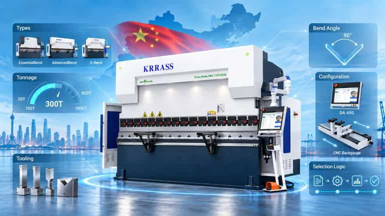
For buyers researching press brake China options, the right machine starts with the parts it must produce. Choose a bending architecture that suits your production mix, calculate the force for the actual material and tooling, and check that the workpiece fits throughout the bend sequence. Then specify the controller, backgauge, tooling, compensation and handling equipment needed to make those parts consistently.
KRRASS’s five published families provide a useful way to organize the choices: EssentialBend for straightforward hydraulic bending, StandardBend for varied CNC hydraulic work, AdvancedBend for more demanding configuration requirements, E-Bend for all-electric bending, and SyncBend for synchronized tandem applications. These are product families with overlapping applications; their names alone do not establish a machine’s capacity or finished-part accuracy.
This guide explains how to choose a press brake from China by machine type, tonnage, working space and configuration. Once the technical requirements are clear, use the China press brake manufacturer shortlist to compare suppliers, and the China press brake purchasing guide for the subsequent procurement process.
Editorial note: KRRASS publishes this guide and supplies press brakes. Product-family descriptions are based on its public catalogue reviewed on October 14, 2026. The numerical examples are hypothetical engineering estimates, not machine test results. Available equipment and performance must be confirmed for the proposed model, tooling and application.
Start Press Brake Selection with Your Part Requirements
A quotation for a “160-ton CNC press brake” leaves important questions unanswered. It does not define the material strength, required bend length, usable space, gauging surfaces or tolerance that will govern the work. A more useful starting point is a representative part package containing your recurring jobs and the parts that are hardest to form.
| Selection input | What to record | Why it matters |
|---|---|---|
| Material and thickness | Grade, condition, thickness range and tensile strength where available | Changes force, springback and feasible bending radius |
| Bend length and geometry | Longest bend, shortest flange, inside radius, box depth and return flanges | Determines tooling choice and whether the workpiece fits |
| Quality requirements | Angle tolerance, flange dimensions, measurement datums and surface finish | Defines the process controls and inspection needed |
| Production mix | Batch sizes, parts per shift, bends per part and changeover frequency | Determines the value of programming, quick clamping and gauge axes |
| Handling conditions | Blank size, weight, rotations and available lifting or support equipment | Influences operator workload, layout and cycle time |
| Workshop conditions | Available floor area, access route, power supply and adjacent processes | Determines whether the complete installation is practical |
Identify the worst case for each constraint. The thickest part may determine force, the longest part may determine bed length, and a much smaller box may determine daylight or punch clearance. Selecting from one convenient demonstration part can miss the job that actually limits production.
Separate routine work from occasional exceptions. If a rare part drives the purchase toward a much larger machine, compare that investment with an alternative production route for the exception. The decision should reflect your actual workload and business priorities.
Press Brake Types: Five KRRASS Families and Their Applications
The five families below are a selection framework drawn from the published KRRASS range. They are not five mutually exclusive engineering types. StandardBend and AdvancedBend both belong to hydraulic CNC bending, while tandem describes a coordinated machine arrangement rather than a separate source of bending force.
| Family | Published machine direction | Suitable starting point for evaluation | Configuration that deserves attention |
|---|---|---|---|
| EssentialBend | Hydraulic bending with mechanical torsion-bar synchronization and NC/CNC control choices | Recurring, relatively straightforward parts with manageable setup requirements | Actual control functions, gauge adjustment, ram synchronization and available crowning |
| StandardBend | CNC hydraulic bending with multi-axis configuration choices | General sheet metal fabrication, cabinets, brackets and mixed batches | Controller workflow, gauge axes, usable workspace and compensation |
| AdvancedBend | Hydraulic CNC family with more extensive published control and backgauge choices | Complex geometry, asymmetric parts and demanding process requirements | Independent gauge-finger movements, programming, measurement options and application testing |
| E-Bend | All-electric servo-driven bending | Repeated smaller parts and work that fits the selected electric machine’s capacity and envelope | Force, bend length, tooling access, handling and production-cycle performance |
| SyncBend | Synchronized tandem bending | Workpieces whose length or forming requirements justify a coordinated dual-machine arrangement | Combined working envelope, permitted loading, synchronization, support and installation layout |
EssentialBend: Straightforward Hydraulic Bending
EssentialBend uses a mechanical torsion bar to link the movement of the left and right sides of the ram. Its published control choices include NC and CNC options, so the family should not be described simply as “all NC.” Equally, a CNC controller on a torsion-bar machine does not make its synchronization equivalent to independent electro-hydraulic ram control.
Consider this direction for recurring brackets, simple channels and other parts where the necessary bends and adjustments are manageable within the proposed configuration. Check how programs are stored, how the backgauge moves, how bend depth is set and which adjustments remain manual. For longer bends, establish whether a suitable crowning arrangement is included.
The important tradeoff is the operator’s work between bends and between jobs. A simpler configuration can be appropriate for stable production; frequent changes in geometry may make additional control and gauging functions more valuable.
StandardBend: General CNC Hydraulic Production
StandardBend is the KRRASS family to examine for varied everyday CNC hydraulic work. Its published backgauge choices include X and R positioning, with an additional arrangement offering Z1 and Z2 movement. The correct choice depends on the surfaces available for gauging your actual parts.
For a workshop making cabinets, equipment covers and brackets in changing batches, evaluate how efficiently the operator can create, recall and correct a program. Check the proposed machine’s bend length, daylight, throat depth, tooling package and crowning alongside its controller.
A general-purpose machine should demonstrate both your recurring work and a difficult representative part. A familiar controller or a generous tonnage rating is useful only when the installed configuration supports the complete bend sequence.
AdvancedBend: More Demanding Geometry and Configuration
AdvancedBend’s published options include a backgauge arrangement with independently controlled X1, X2, R1, R2, Z1 and Z2 axes. This can be relevant when stopfingers need different depths or heights for asymmetric workpieces, or when a varied part mix requires more flexible positioning.
The distinction from StandardBend should be evaluated through the proposed configuration. If both proposals satisfy your drawings, tolerances and setup needs, a family label alone does not establish an advantage. If additional independent finger movements or a particular programming function remove repeated manual adjustments, that is a concrete reason to compare the more extensive package.
For tight tolerances, examine the entire process: material variation, tooling, ram feedback, crowning, gauging and measurement. Do not translate a published axis-positioning figure into a guaranteed flange or bend-angle tolerance.
E-Bend: All-Electric Servo Bending
E-Bend uses an all-electric servo drive for ram motion. That differs from a servo motor powering a hydraulic pump: the latter still generates bending force through a hydraulic circuit. Confirm the architecture rather than relying on the word “servo” in a quotation.
An electric press brake is worth evaluating for repeated smaller brackets, electronic housings and similar work when the selected model provides the required force and working space. Compare complete part cycles, including loading, gauging, bending, repositioning and unloading. Fast ram movement contributes less when most of the cycle is spent handling the part.
All-electric bending removes the ram drive’s hydraulic circuit, but it does not remove maintenance of guides, drive components, tooling or other installed equipment. Energy and productivity comparisons should use equivalent parts, operating periods and measurement boundaries. This guide does not apply a universal savings percentage.
SyncBend: Synchronized Tandem Bending
SyncBend is intended for long workpieces using coordinated dual-machine control. Potential applications include long formed sections and pole-related fabrication, subject to the proposed tooling and machine arrangement.
Treat tandem bending as an engineered system. Adding two nameplate force ratings is insufficient to establish the permitted load for every position along a long part. The proposal must define the combined usable length, loading restrictions, coordination between machines and support through the full forming sequence.
Layout becomes part of the selection. Long blanks need room for loading, rotation and removal, as well as suitable support or lifting equipment. If individual-machine operation is required, confirm that capability and its limits explicitly. Compare a tandem arrangement with a suitable single long-bed machine where both are technically feasible.
You can review the published families through the press brake product range. Use the range to identify candidate configurations, then evaluate them against drawings rather than buying from the series name.
NC, CNC, Hydraulic and Electric: Compare Different Features Separately
These terms describe different aspects of a press brake. Hydraulic and all-electric describe how the ram is driven. NC and CNC describe control capabilities. Torsion-bar and electro-hydraulic synchronization describe how the two sides of the ram are coordinated. Tandem describes the relationship between multiple machines.
For a CNC hydraulic press brake proposal using independent Y1 and Y2 control, check the feedback and synchronization arrangement on the actual machine. For a torsion-bar proposal, establish which ram and gauge functions are programmed and how adjustment is performed. Both questions are more informative than asking whether the machine has a touchscreen.
Also distinguish a controller’s supported functions from the equipment and software actually supplied. Graphical programming, automatic bend sequencing, offline programming and collision checking may depend on the selected model, licenses and configured machine data. A controller brochure does not establish that every feature is active in your order.
The press brake control-system overview can help compare control workflows. For a deeper drive-system comparison, use the hydraulic vs electric press brake guide.
Calculate Press Brake Tonnage for the Actual Bend
Press brake tonnage is the forming force required for a specified job. Thickness alone cannot define it. Material strength, active bend length, V-die opening and forming method must be considered together.
Use the press brake tonnage calculator to make an initial estimate. Select the appropriate material, enter the thickness and bend length, and use the actual V opening of a feasible tool. A preset opening is a starting point; it still needs to produce the required radius and support the flange.
The calculator’s published air-bending baseline is:
P = 650 × S² × L ÷ V × (UTS ÷ 450)
Here, P is force in kN; S is thickness in mm; L is active bend length in meters; V is die opening in mm; and UTS is tensile strength in MPa. The baseline is 450 MPa mild steel. Divide kN by 9.80665 to obtain metric tonne-force. Metric tonnes of force and US short tons of force are different units, so keep the unit label when comparing quotations.
The material values in a calculator are representative inputs. Actual grade, temper and material certificates take precedence over a generic preset. The formula is an air-bending estimate; it does not approve bottoming, coining, hemming, offset tooling or a special forming operation.
A Worked Air-Bending Example
Assume a straight air bend in 3 mm mild steel with tensile strength of 450 MPa, a 2,000 mm active bend length and a 24 mm V-die opening. This is a hypothetical sizing exercise, not a production recommendation.
Convert the bend length to meters before calculating:
P = 650 × 3² × 2 ÷ 24 = 487.5 kN
487.5 ÷ 9.80665 ≈ 49.7 metric tonnes of force
The calculator suggests a 20–25% allowance for initial air-bending machine sizing. Applying 25% to this example gives approximately 62.1 metric tonnes. That is a preliminary capacity target, subject to the machine’s permitted loading, actual material variation and tooling limits. It does not identify a suitable model by itself.
| Hypothetical air-bending condition | Estimated force | Preliminary capacity with 25% allowance |
|---|---|---|
| 3 mm, 450 MPa material, 2 m bend, V = 24 mm | 487.5 kN / 49.7 metric tonnes | 62.1 metric tonnes |
| Same material, thickness and length, V = 18 mm | 650.0 kN / 66.3 metric tonnes | 82.9 metric tonnes |
| 3 mm, 650 MPa material, 2 m bend, V = 24 mm | 704.2 kN / 71.8 metric tonnes | 89.8 metric tonnes |
The second row shows why a smaller V opening can change machine sizing. The third shows the effect of higher tensile strength under the same calculation assumptions. Neither change should be made without checking the resulting radius, flange support, springback and tooling suitability.
Check Tooling and Local Load Limits as Well as Total Force
The force estimate must be checked against the load ratings of the punch, die, holders, adapters and machine. Short bends can concentrate force over a small tool length. Off-center work and multiple tooling stations can also introduce loading conditions that a total-tonnage comparison misses.
Steven D. Benson’s presentation on the four pillars of press brake tonnage limits distinguishes forming demand from tool-load, tool-seating and centerline-load limits. These checks explain why available nameplate tonnage alone cannot approve a setup. Use the documented ratings for your machine and every loaded tooling component.
If a required part exceeds a limit, increasing the machine size is only one possible route. A different feasible die opening, forming method or production process may change the requirement. The chosen route still needs application-specific verification.
Check Bending Length and Working Space Through the Full Sequence
Working space often rules out a machine that appears suitable from its force rating. Check the finished shape at each bend, including rotation and removal after the last operation.
| Machine dimension or limit | What it controls | Selection check |
|---|---|---|
| Usable bending length | Length available for the proposed tooling and bend | Confirm the required tool arrangement and full active bend fit |
| Distance between uprights | Clear width inside the side frames | Check whether projecting flanges or deep sections interfere with the frames |
| Throat depth | Space available at the side-frame throat | Check insertion and rotation of the actual part at those positions |
| Daylight or opening height | Vertical opening available at maximum ram opening, as defined in the specification | Evaluate usable clearance after holders, adapters, punch and die are installed |
| Ram stroke | Available ram movement | Check approach, forming travel and clearance needed for part removal |
| Backgauge travel and access | Reachable positioning range and usable contact locations | Confirm each flange can be located without a collision or unsupported contact |
A deep box may need taller tooling and more opening height than a flat bracket. A long panel may fit the nominal bending length while its return flange interferes with a side frame. A narrow part may fit everywhere but offer no suitable surface for the proposed stopfingers.
Machine datasheets may measure daylight from different reference surfaces. Obtain a clear drawing showing the stated dimensions and the installed tooling stack. Subtracting punch and die heights is an initial clearance check, not a substitute for evaluating the three-dimensional part.
Check the workshop envelope too. The machine footprint excludes space for blank staging, operator movement, long-part rotation and finished-part storage. For large sheets, include the handling system in the layout review.
Choose Backgauge Axes from the Surfaces You Need to Locate
Additional axes are useful when they position the part in a way your jobs require. Count the relevant movements rather than comparing an unexplained “six-axis” or “eight-axis” label.
X commonly controls gauge depth and R controls gauge height. Z1 and Z2 position the stopfingers along the bending length. Arrangements using X1/X2 or R1/R2 allow the fingers to have different depth or height positions. The exact axis map and travel belong in the configuration sheet.
An X-and-R arrangement may suit many conventional parts. Powered Z movement can help with changing contact positions, while independent finger movements may be useful for asymmetric geometry. None of these arrangements removes the need for a stable gauging surface or appropriate tooling clearance.
For each representative part, identify the contact surface used on every bend. Check whether the surface exists at that stage, whether the fingers can reach it, and whether a previous flange blocks access. Irregular blanks, tapered parts and already formed sections deserve particular attention.
Confirm how the supplier counts axes. A quoted total may include ram axes and crowning rather than describing only the backgauge. Two machines with the same advertised count can therefore have different positioning capabilities.
Match Tooling, Crowning and Angle Control to the Part
Choose tooling before treating the force estimate as final. The die opening affects forming demand and bend geometry, while punch shape determines access around return flanges and already formed features. Check minimum flange support, required inside radius, surface marking, segmentation and mounting compatibility as a complete package.
Gooseneck tooling may provide clearance for a return flange, but its geometry and load rating must suit the job. Taller tooling may help a box sequence while reducing available daylight. Hemming and offset tools create different load conditions from a conventional single air bend. These decisions should be made from the actual drawing and tool data.
The press brake tooling selection guide covers punch, die and V-opening choices in more detail. Specify actual tool profiles, lengths and load ratings rather than accepting “standard tooling included” as a complete description.
Crowning compensates for deflection of the loaded machine and tooling system to help control angle variation along the bend. Establish whether the proposed system is manual or CNC controlled, how it is set for the job and which loading arrangements it supports. Compensation cannot authorize overload or correct every material and setup problem.
Angle measurement is a separate function. It may help assess springback and support corrections, but its coverage depends on the installed system, accessible measurement locations and part geometry. Check whether a quotation includes measurement hardware, the necessary software and the relevant control function. A laser alignment aid, a safeguarding laser and an angle-measurement system serve different purposes.
Evaluate Productivity, Handling and Safety Together
For high-mix work, setup can matter as much as bending speed. Compare program creation, tool selection, clamping, first-part correction and job recall. For repeated work, compare the complete cycle and the operator’s handling burden.
Supports or followers can be valuable where a large blank needs assistance during forming. Confirm the proposed support’s load capacity, travel, interference clearance and suitability for the part. An accessory that works with a broad panel may not suit a small or irregular component.
In US workplace guidance, OSHA’s powered press brake eTool identifies hazards at the tooling and between a moving workpiece and the machine, as well as accidental cycling risks. This is a US safety reference; the appropriate safeguarding arrangement must be assessed for the destination, machine, tooling, part and operating method.
Include access from the sides and rear, tool changes, maintenance and any multiple-operator work in that assessment. A component name on a quotation does not establish that the complete installation is suitable. Safety devices and operating procedures need to work with the intended application.
Training also affects whether the selected configuration can be used effectively. PMA’s METALFORM EDU course catalogue includes press brake operations and safety training. For a new installation, define training around the actual controller, tooling, gauging, inspection and safe handling tasks your team will perform.
Match Common Applications to a Configuration
The following examples are selection scenarios, not customer case studies or automatic machine recommendations. Each starting point still requires the force, geometry and process checks described above.
| Production scenario | Machine direction to investigate | Configuration likely to matter most |
|---|---|---|
| Recurring simple brackets and channels | EssentialBend; compare StandardBend if setup requirements justify it | Suitable tooling, reliable gauging, program recall and manageable manual adjustment |
| Mixed cabinets, covers and general fabrication | StandardBend; compare AdvancedBend for demanding geometry | Programming workflow, gauge contact positions, crowning and space for box sequences |
| Asymmetric or complex precision components | AdvancedBend or another configuration meeting the demonstrated requirement | Independent finger movements, collision review, material control and inspection |
| Repeated smaller parts within an electric model’s envelope | E-Bend, compared with a suitable hydraulic CNC alternative | Actual cycle, tool access, handling, force and working space |
| Long formed sections | SyncBend or a suitable single long-bed machine | Usable length, permitted loading, coordinated control and workpiece support |
| Thick or high-strength material | An appropriately rated hydraulic or tandem proposal, subject to application review | Calculated forming demand, local tool loads, radius feasibility and heavy-part handling |
For an enclosure shop, the deepest box and the most awkward return flange may matter more than maximum nominal thickness. For a bracket producer, the gauge sequence and repeat setup can matter more than a large bed. For long-section production, safe handling and permitted loading form part of the machine specification.
Choose the configuration that solves those particular constraints. An industry label such as “automotive” or “aerospace” does not, by itself, define the necessary accuracy, traceability or acceptance criteria.
Validate the Proposed Machine with Representative Parts
A meaningful application trial should use material, tooling and geometry representative of your intended production. Include a recurring part and at least one part that challenges the proposed configuration’s space, gauging or load requirements.
Record the material condition, tooling identifiers, V opening, bend sequence, control configuration and corrections made. Measure the specified angle and dimensional features using defined datums. For a long bend, inspect more than one position along its length.
Observe how the part is loaded, supported, repositioned and removed. Record the complete cycle where throughput matters, including setup and first-part correction when evaluating high-mix work. A video of rapid unloaded ram motion cannot establish parts per shift.
Machine positioning repeatability and finished-part accuracy are different measurements. A trial should show whether the complete process meets your drawing under agreed conditions. Document which deviations require a tooling change, control adjustment or different machine configuration before finalizing the technical specification.
Turn the Selection into a Clear Machine Specification
Your selection should finish with a configuration that another engineer can check. Include the material and part package, forming method, force estimate, active bend length, workspace requirements, axis map, controller functions, tooling and load ratings, crowning, measurement options, handling and safeguarding scope.
Distinguish required equipment from optional additions. If offline programming, special tooling, independent gauge movements or sheet support are necessary for the proposed workflow, identify them explicitly. This makes proposals from different manufacturers easier to compare on the same production task.
At this stage, use the manufacturer shortlist to select which companies can supply and demonstrate the configuration. The purchasing guide then addresses RFQs, trading-entity verification, inspections, import arrangements, acceptance and after-sales responsibilities.
To discuss a KRRASS configuration, send your bending requirements with drawings, material grades, thickness range, longest bend, shortest flange, required radius, tolerances and production mix. Include the tonnage-calculator inputs and any workspace or handling constraint. Those details support a more useful recommendation than a requested tonnage alone.
Frequently Asked Questions About Press Brake China Selection
Which Type of Press Brake Should I Choose from China?
Start with the parts and workload. Evaluate a simpler hydraulic configuration for manageable recurring bends, CNC hydraulic bending for varied work, all-electric bending where the selected model fits the application, and tandem equipment where long-workpiece requirements justify it. Complete the force, tooling, space and handling checks before choosing a family.
Is a CNC Press Brake Always Better Than an NC Press Brake?
CNC functions can be valuable for varied geometry, programmed positioning and frequent changes. A simpler NC configuration may suit recurring straightforward work. Compare the actual functions, synchronization, gauge hardware and operator adjustments required for your parts. The control label alone does not establish suitability.
Is a Servo-Hydraulic Press Brake the Same as an Electric Press Brake?
A servo-hydraulic machine uses a servo-driven hydraulic power arrangement; an all-electric machine drives ram motion through an electric mechanical system. Confirm the architecture, available force and working envelope. The presence of a servo motor alone does not mean the bending drive is all-electric.
How Do I Know What Tonnage Press Brake I Need?
Estimate the force from material strength, thickness, active bend length, V opening and forming method. Use the linked calculator for initial air-bending sizing, then verify machine loading limits and all tooling ratings. Also confirm that the required bend sequence fits the proposed machine.
Can a 100-Ton Press Brake Bend the Same Thickness at Every Length?
No. For the same material, thickness, die opening and air-bending assumptions, estimated forming force increases with active bend length. A capacity statement needs those conditions and the applicable tooling and machine limits. “100-ton” alone does not define a maximum thickness.
How Many Backgauge Axes Do I Need?
Choose the movements needed to locate each part during its bend sequence. X and R may cover many conventional jobs; Z movement and independent finger axes can help with changing or asymmetric contact surfaces. Obtain the axis map because advertised counts may include ram control and crowning.
When Should I Consider a Tandem Press Brake?
Consider tandem bending when the workpiece length or forming requirements justify coordinated machines. Confirm combined usable length, permitted load distribution, tooling, synchronization and handling. Compare it with a suitable single long-bed machine where both can perform the work.
Does More Tonnage Guarantee Better Bending Accuracy?
More capacity provides force headroom under the permitted loading conditions. Finished-part quality also depends on material consistency, tooling, gauging, ram control, compensation and measurement. Select sufficient capacity and validate the complete process against your drawing.
Share