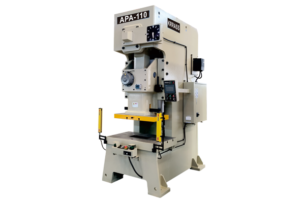
APA C Frame Pneumatic Power Press

APA C Frame Pneumatic Power Press
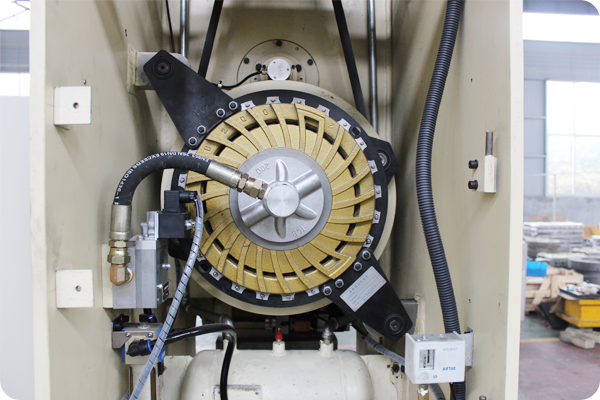
APA Series pneumatic power press machine adopted Japanese technology wet clutch is featured of stable working performance, high production efficiency, low noise, and less maintenance cost. Equipped with Japan SHOWA hydraulic overload protection pump ensuring longer service life. Its the most practical and mature small size stamping presses in the stamping field in recent years. Highly recommended for production of metal pieces.


We have designed the APA-series c-frame pneumatic power press with different power ranges, from 25to 400 tonnes.

Specifically designed to perform work involving deep-drawing, stamping, die-cutting, forming, etc.

The latest generation APA series hydraulic presses now feature a wide range of uses including the possibility of incorporating these machines in automatic production lines.
- Mitsubishi - Japan
- Electrics: Schneider Electric - France
- Main Motor: Siemens Motor - Germany
- Foot Switch: KACON - South Korea
- Hydraulic System: Bosch Rexroth - Germany
- Oil Pump: Sunny - USA
- Sealing Ring: PARKER - America
- High Efficiency Motor - Class IE3
Standard Equipment
Introduction to Configuration
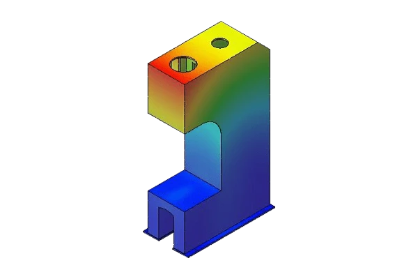
FEA & Stress Analysis
Stress Analysis & Finite Element Analysis
The CAE software SOLIDWORKS used as the method to analyze the linear static construction, stress and deformation for press break and laser cutting machine frames. So for complicated structures, highly complex loading’s, transient modelling and combination of the above, FEA makes sense.
Structure and Tables
KRRASS has invested huge amount for the most advanced production equipment from all over the world. including 12 sets of Italy PAMA CNC boring and milling machine, German Gleason grinding machine, German Liebherr gear hobber, Japan TOSHIBA CNC machining center, etc.
With powerful productivity and excellent production equipment, more than 85% mechanical parts are self-produced by World Press for JH21 Series C type press machine.
From structure buidling to final assembling, JH21 is followed in the highest Japanese JIS1 standard. Compact structure and high-graded configuration ensure reliable working performance and long service life.
Features
- Steel welded body, tempering treatment or VSR(Vibratory Stress Relief), high rigidity, accuracy and stability.
- Pneumatic dual balance cylinders, which balance the slide and punch weight to reduce noise and impact.
- The crankshaft undergoes gringding treatment after high frequency quenching.
- Lengthened six-face rectangle guide with a surface of bronze plate.
- Vertical located crankshaft, compact structure.
- PLC control and imported safety duplex valve.
- Wet type combined multi discs friction clutch and brake.
- Hydraulic onerload protected.
Electric Installation and Safety
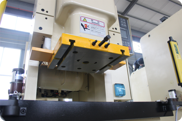
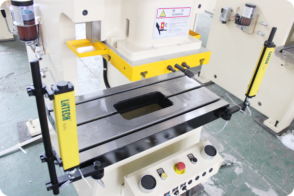
The control panel features a switch enabling the user to select the desired type of work in a manual, semi-automatic or automatic position and a switch to select either the fast speed or slow speed. Electrical and hydraulic manoeuvres are redundant and self-controlled. They incorporate an additional safety block and self-control devices for manoeuvre and safety. It includes the verification and certification of the correct operation and the safety distance for the photocells.
Operation is carried out by low voltage electric pedals.
Safety is guaranteed by the use of two lateral protections and with level IV safety light curtains situated at the front.
They allow the installation of a hydraulic cushion or a hydraulic ejector. They are supplied with an instructions manual.
It meets and satisfies all the essential health and safety requirements in accordance with the EC standard.
Technical Parameters
| Items | Unit | APA-15A | APA-25A | APA-35A | APA-45A | APA-60A | APA-80A | APA-110A | APA-160A | APA-200A | APA-260A | APA-315A | APA-400A | ||||||||||||
| V | V | H | V | H | V | H | V | H | V | H | V | H | V | H | V | H | V | H | V | H | V | H | |||
| Capacity | Ton | 15 | 25 | 35 | 45 | 60 | 80 | 110 | 160 | 200 | 260 | 315 | 400 | ||||||||||||
| Rated Tonnage Point | mm | 1 | 3.2 | 1.6 | 3.2 | 1.6 | 3.2 | 1.6 | 4 | 2 | 4 | 2 | 6 | 3 | 6 | 3 | 6 | 3 | 7 | 3.5 | 8 | 4 | 8 | ||
| Stroke of slide | mm | 60 | 60 | 30 | 70 | 40 | 80 | 50 | 120 | 60 | 150 | 70 | 180 | 80 | 200 | 90 | 200 | 100 | 250 | 150 | 250 | 150 | 300 | ||
| Stroke/min | Variable | S.P.M | 120-180 | 60-140 | 130-200 | 40-120 | 110-180 | 40-100 | 100-150 | 35-90 | 80-120 | 35-80 | 80-120 | 30-60 | 60-90 | 20-50 | 40-70 | 20-50 | 50-70 | 20-40 | 40-50 | 20-40 | 40-50 | 20-35 | |
| Fixed | S.P.M | 130 | 110 | 85 | 75 | 65 | 65 | 50 | 35 | 35 | 30 | 30 | 30 | ||||||||||||
| Max Die Height | mm | 200 | 200 | 215 | 220 | 235 | 250 | 265 | 310 | 340 | 340 | 380 | 360 | 410 | 460 | 510 | 460 | 510 | 500 | 550 | 500 | 550 | 550 | ||
| Die Height Adjustment | mm | 50 | 50 | 55 | 60 | 75 | 80 | 80 | 100 | 110 | 120 | 120 | 120 | ||||||||||||
| Slide Area | mm | 300×230×50 | 470×250×50 | 520×285×50 | 560×300×60 | 700×400×70 | 770×420×70 | 910×470×80 | 990×550×90 | 1130×630×90 | 1130×700×100 | 1130×700×100 | 1050×840×95 | ||||||||||||
| Bolster Area | mm | 680×300×70 | 680×300×70 | 800×400×70 | 850×440×80 | 900×500×80 | 1000×550×90 | 1150×600×110 | 1250×800×140 | 1400×820×160 | 1500×840×180 | 1500×840×200 | 1800×950×200 | ||||||||||||
| Shank Hole Size | mm | Ø38.1 | Ø38.1 | Ø38.1 | Ø38.1 | Ø50 | Ø50 | Ø50 | Ø65 | Ø65 | Ø65 | Ø65 | Ø65 | ||||||||||||
| Main Motor | KWXP | 2.2×6 | 4×4 | 4×4 | 5.5×4 | 5.5×4 | 7.5×4 | 11×4 | 15×4 | 18.5×4 | 22×4 | 30×4 | 37×4 | ||||||||||||
| Capacity Of Die cushion | Ton | — | — | 2.3 | 2.3 | 3.6 | 3.6 | 6.3 | 10 | 14 | 14 | 14 | 14 | ||||||||||||
| Stroke Of Die cushion | KW | — | — | 50 | 50 | 70 | 70 | 80 | 80 | 100 | 100 | 100 | 100 | ||||||||||||
| Die Cushion Effective Area | Ton | — | — | 300×230 | 300×230 | 350×300 | 450×310 | 500×350 | 650×420 | 710×480 | 810×480 | 810×480 | 810×480 | ||||||||||||
| Air pressure | Kg/cm² | 6 | 6 | 6 | 6 | 6 | 6 | 6 | 6 | 6 | 6 | 6 | 6 | ||||||||||||
| Overall Dimensions | L×R | mm | 740 | 840 | 900 | 950 | 1000 | 1170 | 1290 | 1390 | 1680 | 1850 | 1850 | 2090 | |||||||||||
| F×B | mm | 1264 | 1334 | 1384 | 1584 | 1604 | 1779 | 1904 | 2324 | 2624 | 2799 | 2799 | 2854 | ||||||||||||
| H | mm | 2098 | 2179 | 2348 | 2525 | 2808 | 3040 | 3224 | 3600 | 4058 | 4430 | 4450 | 4615 | ||||||||||||
| Prsee Precision | GB (JIS) Level 1 | ||||||||||||||||||||||||
Reviewed by 3 users
Enhancing the user interface and controls for this punching machine could improve the ease of operation and efficiency of the press,good
JH21-63 Pneumatic Punching Machine is simple to install and easy to operate. After the product is stretched, it has high precision and meets the requirements. KRRASS is a trusted seller!
The quality of JH21-110T Pneumatic punching machine is very good, and the communication with the professionals is smooth.