Description
This manual is the IPG laser source manual. The IPG laser source has been developed to meet industrial market demands of efficient reliable maintenance-free high power lasers. YLR products are diode-pumped ytterbium fiber lasers with output powers ranging from 20 W up to 1.5 kW operating at the wavelength region of 1060 – 1100 nm. These lasers can be air or water-cooled. The wall plug efficiency of an YLR laser typically exceeds 30%. All IPG YLR-Series fiber lasers are Class 4 laser products and are designed and tested with safety in mind. By following this User‟s Guide and applying sound laser safety practices, it will be a safe and reliable device. Laser light exhibits unique characteristics that pose safety hazards that are not normally associated with other light sources. Therefore, all operators and people near the laser must be aware of these special hazards.
In order to ensure the safe operation and optimal performance of the product, please follow these warnings in addition to the other information contained elsewhere in this manual. These safety precautions must be observed during all phases of operation, maintenance, and service of this instrument.
Operators are urged to adhere to these recommendations and to apply sound laser safety practices at all times. Never open the device. There are no user serviceable parts (internally), equipment or assemblies associated with this product. All internal service and maintenance will be performed only by qualified IPG personnel.
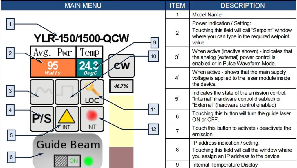
Touch-screen Display
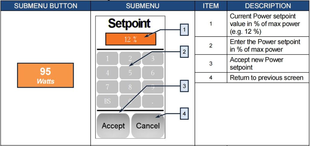
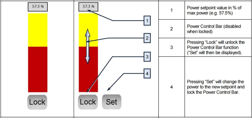
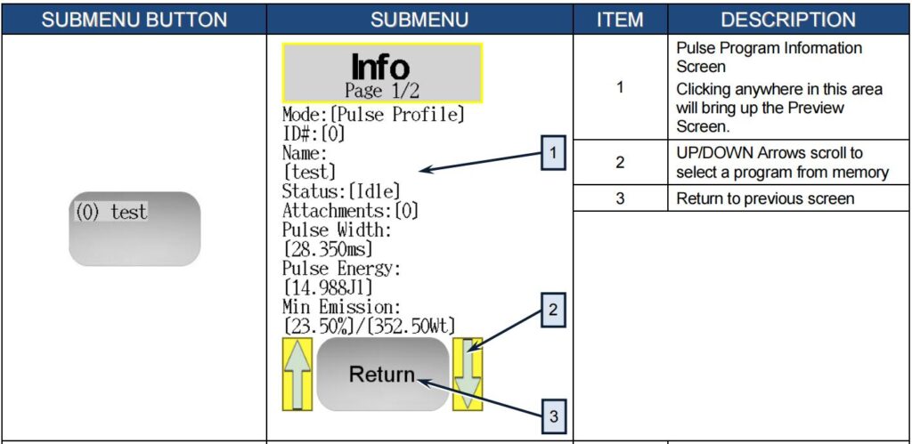
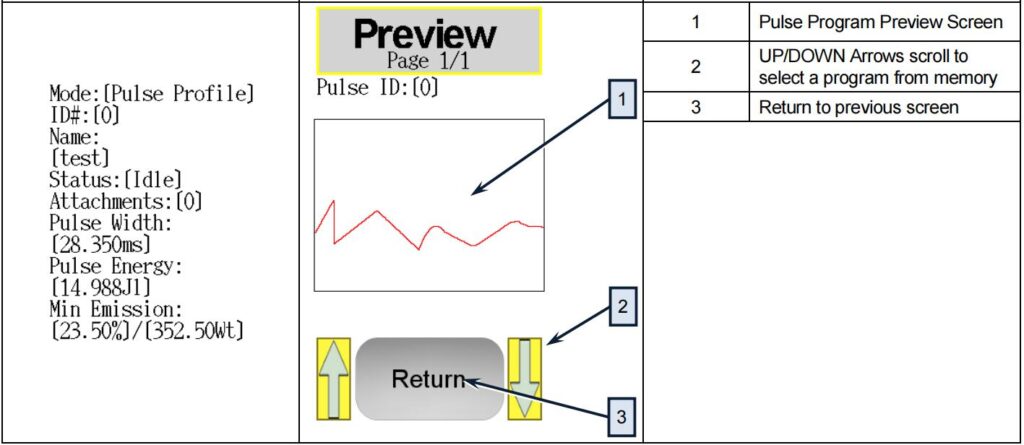
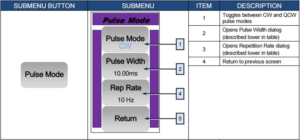
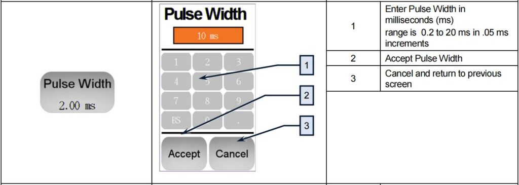
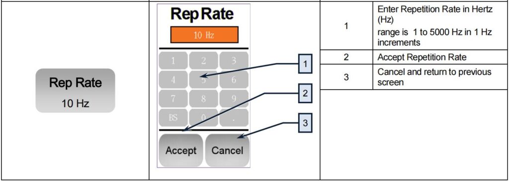
The touch-screen display is used for manual control from the front panel of the device and for the indication of information about the state and settings of the device. In addition, activating certain commands from the main window will invoke additional submenu windows. In remote mode, the touchscreen display function is disabled and can only be used for display purposes.


COMPUTER IINTERFACE // COMMANDS
RS-232 Configuration
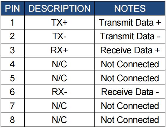
A three wire (RxD, TxD, GND) interface is used (null modem cable). The individual commands are described in the “Interface Commands” section of the manual. The RS-232 interface is configured with the following parameters:

Ethernet TCP/IP Interface
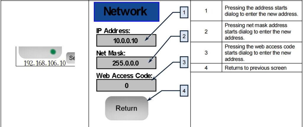
The IP address of the laser will be shown on the front panel of the laser. Touching the screen where the address is shown will bring up the network setup menu where the network settings can be changed. The laser will listen for connections on port 10001. The command must be sent as a single string in a single packet. The individual commands are described in the “Interface Commands” section of the manual.
Interface Commands
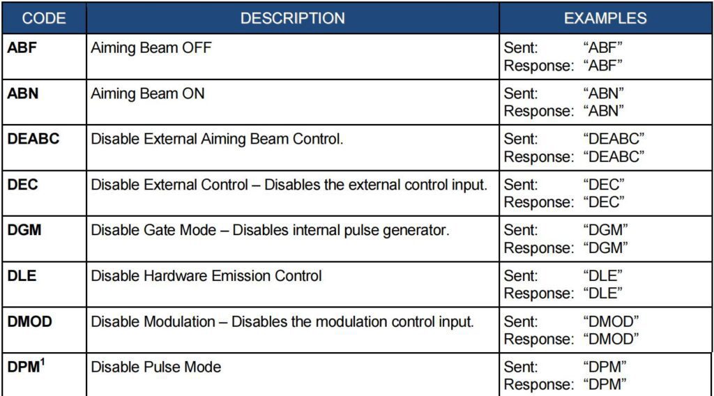
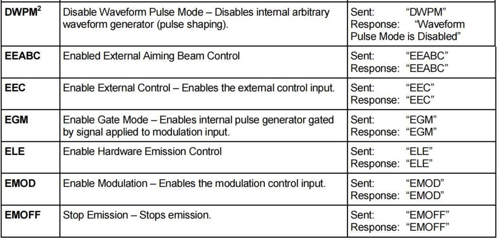
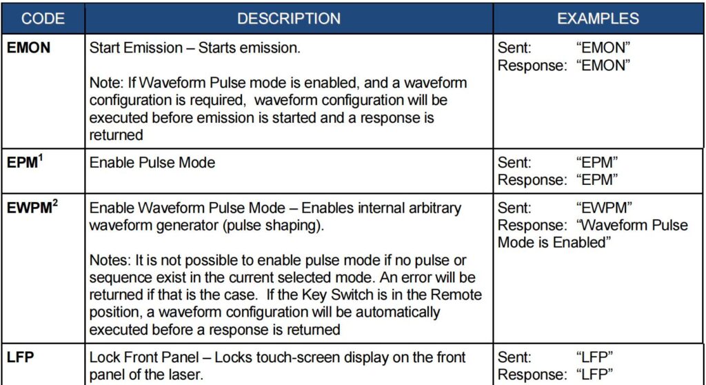
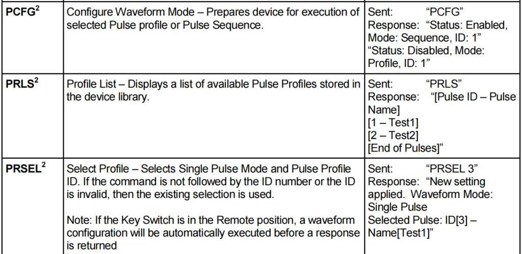
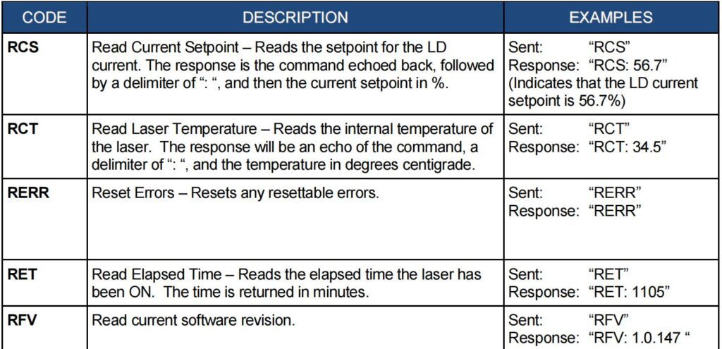
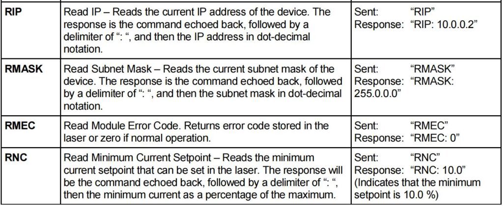
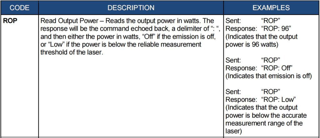
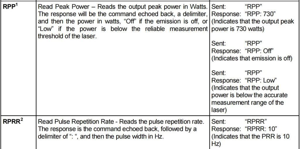
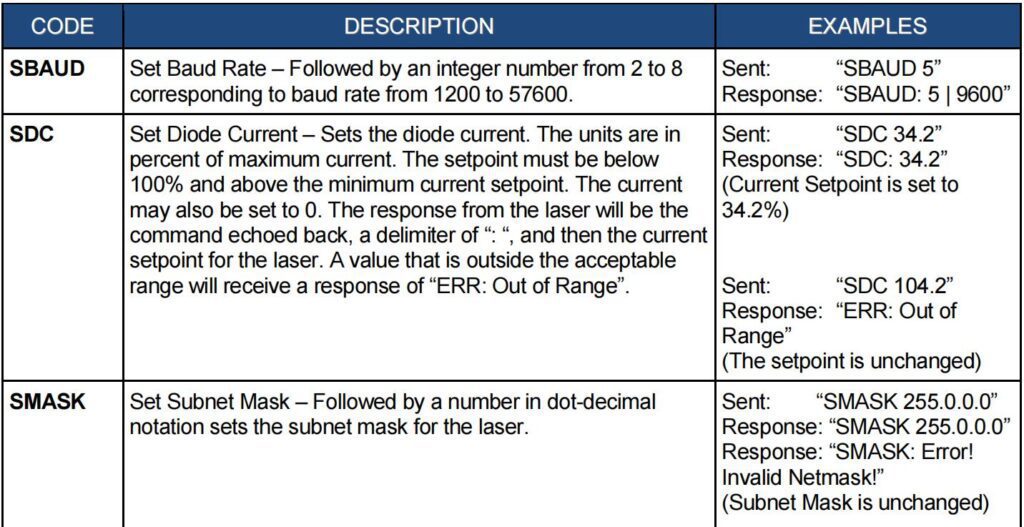
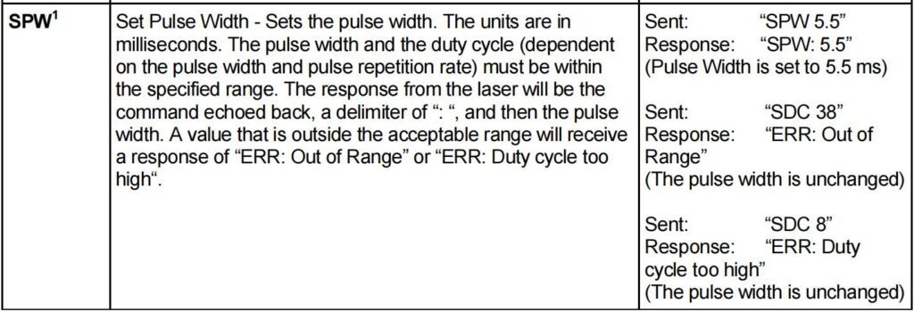
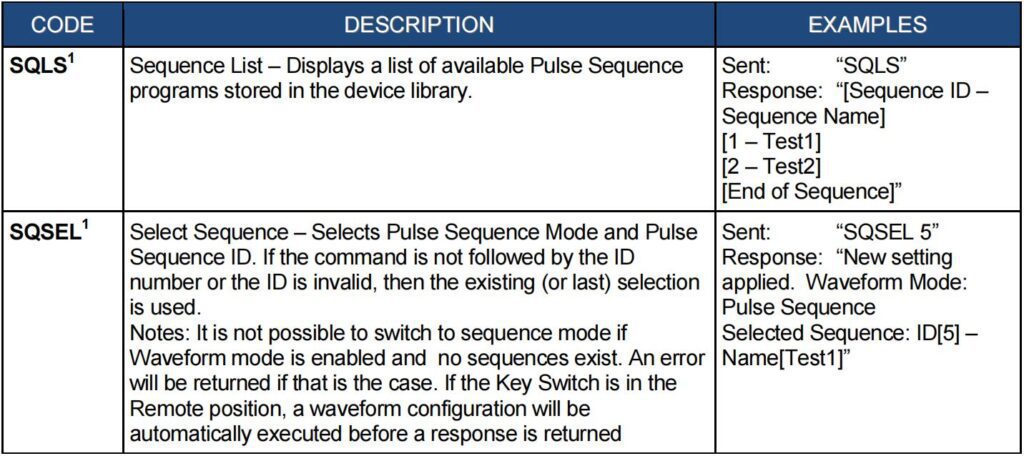
All commands and responses will consist of printable ASCII characters. Commands are typically three or four letter mnemonic codes followed by a parameter, if required.
All commands and responses will be terminated with a <Carriage Return> (CR, 0x0D, r) character If a CR terminated string is received, but no valid command is found, a response of “BCMD” will be sent.
The commands are shown here as all uppercase for clarity; the actual commands are not case sensitive.
A space character is also shown between the command and parameter for clarity. The space is not required.
Every command will generate a response. The responses generally consist of the command echoed back.
If there is a returned value, it will be separated from the echoed command by a „:‟ character.



PULSE SHAPIING SOFTWARE OPTION
Introduction
The optional Pulse Shaping software was developed to aid users of IPG mid-power lasers in creating effective pulse shapes to meet the ever-changing requirements of their applications.
PC Host Requirements
The following items are the minimum requirements for installing and using the MPPS software:
An x86 machine, with at least 512MB RAM, 5GB hard disk, mouse and keyboard, VGA monitor and a Ethernet or Serial (RS-232) communication port
Operating System: Windows 2000 or later w/ .NET framework version 2.0 or higher
PulseShapingGUI: Designated release version executable
Ethernet TCP/IP Interface
The IP address of the laser will be shown on the front panel of the laser. Touching the screen where the address is shown will bring up the network setup menu where the network settings can be changed. The laser will listen for connections on port 10001. The command must be sent as a single string in a single packet. The individual commands are described in the “Interface Commands” section of the manual.
RS-232 Configuration
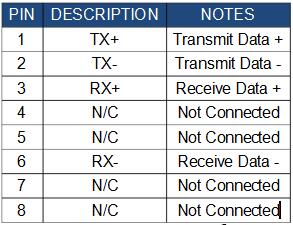
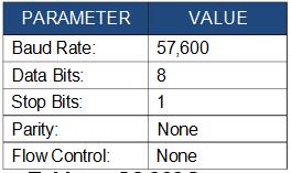
A three wire (RxD, TxD, GND) interface is used (null modem cable). The individual commands are described in the “Interface Commands” section of the manual. The RS-232 interface is configured with the following parameters:
Installing the Software
To install this software package, run PSG installer as it will create a new folder with the pulse editor program.
- Computer Configuration Procedure
Both Ethernet and Serial communications require you to configure the communication protocols of your computer in order to connect to the Laser via a PC.
- Ethernet Configuration Option
The following procedure assumes that the user is already familiar with operating their respective laser. In addition, it is strongly recommended that you review all safety and operational procedures before proceeding.
- Connect PC to the Laser using crossover cable.
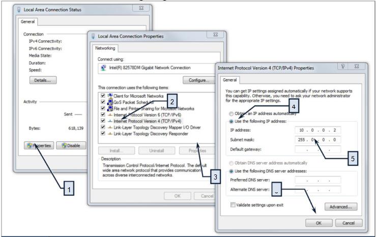
- Manually configure the Local Area Connection settings for Ethernet (refer to Table 12).
- Start the PSG application (PSG.exe).
- Click Session->Ethernet
- Enter the IP address of the laser, then click Connect
- Ensure the connection is successful, and the status is displayed in the Connection indicator:
IP:<Current IP>~Good~
Serial Communication Port Configuration Option
The following procedure assumes that the user is already familiar with operating their respective laser. In addition, it is strongly recommended that you review all safety and operational procedures before proceeding.
- Connect serial RS-232 cable from PC Host to the Laser.
- Click Session->Serial Port
- Enter the Com port the is attached to the laser, then click Connect
- Ensure the connection is successful, and the status is displayed in the Connection indicator:
Port:<COMx>~Good~
STEP DESCRIPTION
- Navigate to the Local Area Connection screen on your computer and click the “Properties” command button.
- Select the Internet Protocol TCP/IP Setting (TCP/IP 4 on Windows 7 OS).
- Click the Properties command button.
- Click the Radio Button to “Use the following IP address” to manually assign the IP adress.
- Assign the IP address to 10.0.0.x (x can not be 10 as 10.0.0.10 is the default IP address of the Laser). Assign the Subnetmask to its default setting to 255.0.0.0 by clicking on the Textbox.
- Pres the “OK” command button to accept these manual changes.
Quick Start Guide
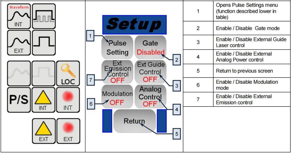
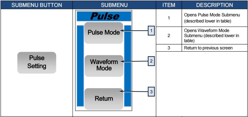
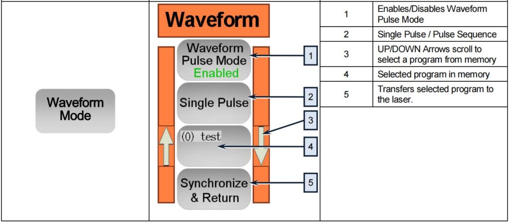
The following procedures assume that the user is already familiar with operating their respective laser and with the touch screen menu items found Figure 13 and Figure 14. In addition, it is strongly recommended that you review all safety and operational procedures in the laser’s user guide that was supplied with your laser.
- Start the PSG application
- If you‟re using the network to connect to the Laser:
- Click Session->Ethernet
- Enter the IP address of the laser, then click Connect
- Ensure the connection is successful, and the status is displayed in the Connection indicator:
IP:<Current IP>~Good~ - If you‟re using the serial port to connect to the Laser:
- Click Session->Serial Port
- Enter the Com port the is attached to the laser, then click Connect
- Ensure the connection is successful, and the status is displayed in the Connection indicator:
Port:<COMx>~Good~ - In the Profile panel, Enter a desired Time Scale
- Click around in the pulse chart to plot a simple pulse
- Click Laser Operation ->Write Profile, then select an empty slot, click Write Profile and enter a unique name, then click OK.
- In PSG, click clear in the Editing panel, then click Laser Operations->Read Profile and select the recently created pulse and click Read Profile to see what was saved in the laser Pulse Profile library.
- Create more Pulse Profiles required for your applications. Up to 100 profiles can be stored in the laser Pulse Profile library.
- Click Sequence Editor, In the Arrangement panel click Add, then select the first created pulse under Pulse Profile, click Add again and select the second pulse under Pulse Profile, enter a Pre-Delay value to set pulse repetition rate.
- In the Sequence panel, set the number of Repeats required for the application.
- Use the horizontal scroll bar to see the entire sequence preview
- Click Laser Operation ->Write Sequence, then select an empty slot, click Write Sequence and enter a unique name, then click OK.
- Create more programs (Pulse Sequences) required for your applications. Up to 100 sequences can be stored in the laser Pulse Sequence library.
Pulse Generator (Waveform Mode)
The touch-screen display (refer to Figure 13 and Figure 14) is used for manual control from the front panel of the device and for the indication of information about the state and settings of the device. In addition, activating certain commands from the main window will invoke additional submenu windows of the Pulse Profile selection. Likewise, the Pulse Generator commands will invoke submenus of the touch screen control.
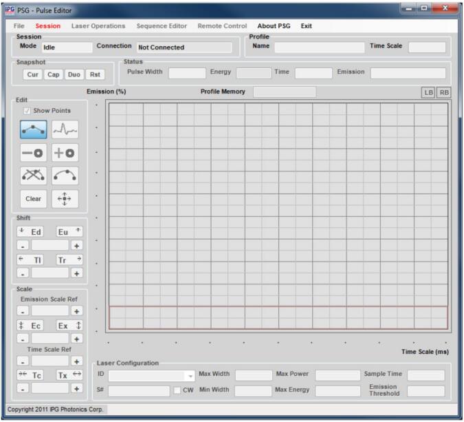
PSG Pulse Editor Main Screen
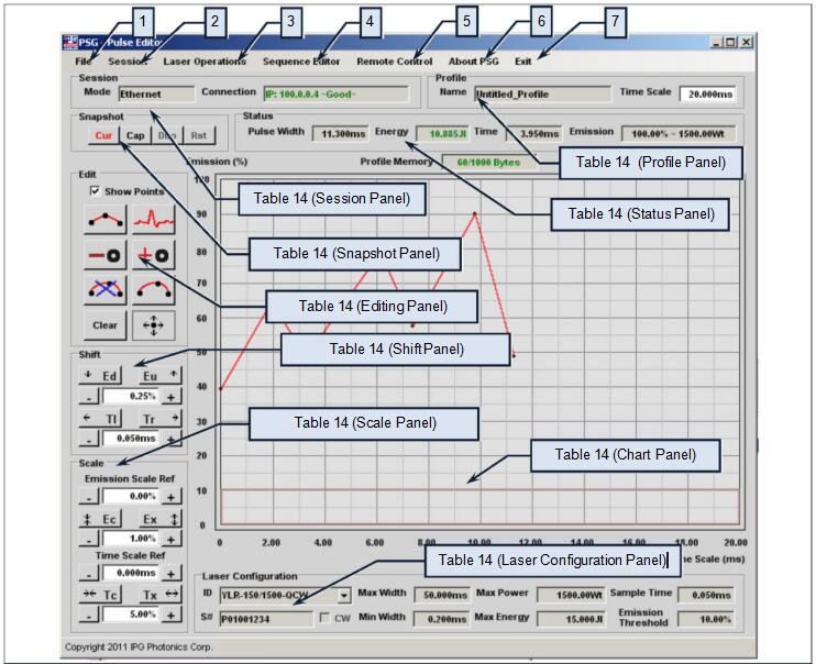

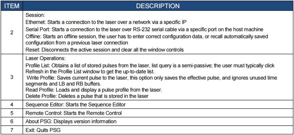
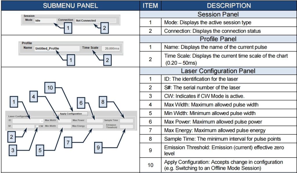

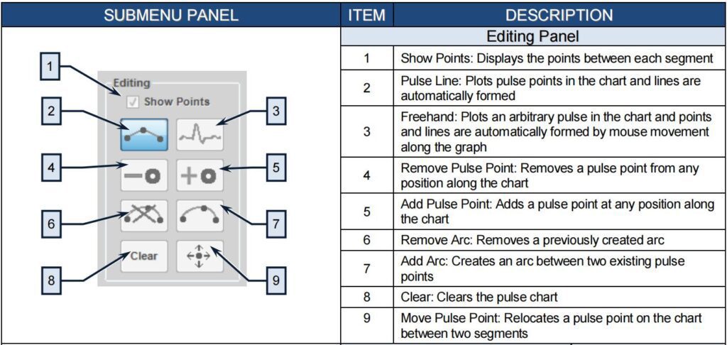

Pulse Editing
For the following section, please pay attention to the Energy indicator in the Status panel, if it glows red that means you have exceeded the pulse energy limit and automatic correction has occurred, which mean your pulse is being changed automatically. To avoid pulse energy limits, either shorten your pulse widths, or reduce the value of Time Scale in the Profile panel.
Change Time Scale value to zoom in and out then use the time shift controls and alignment cursors for more accurate editing, and always use the Time and Emission indicators in the Status panel for guidance.
Please note that every time a change is made to the pulse, the Pulse Width and Energy indicator are updated to reflect the current sketched pulse, PSG will not allow you to exceed the limits established in the Laser Configuration.
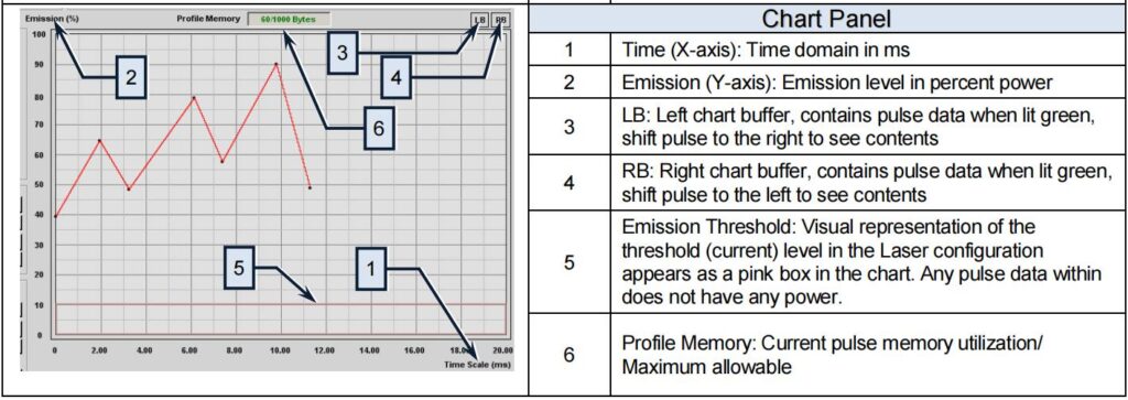
A laser emission pulse is a custom time-based emission power signal, constrained by an output sample time, maximum power, maximum energy and minimum current (power) threshold, all of which are preconfigured in the laser. PSG allows sketching of pulse points, and automatically fills in pulse (power level) lines, and computes all the emission pulse characteristics simultaneously, it also perform auto-correction in case constraints are violated.
Please note the pulses are not zeroed visually when they go under the power threshold, although that‟s not reflected in the pulse energy calculation.
Sketching a Pulse
For simple applications, a single Pulse program may be required. The following procedure demonstrates how to create and load a single pulse program.
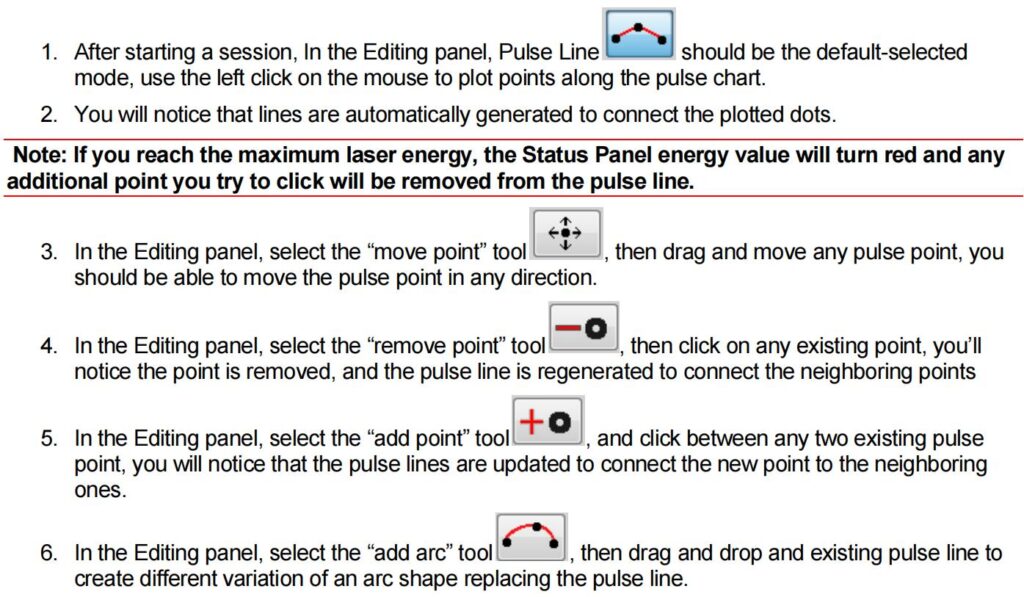

Shifting a Pulse
The Modulation panel in PSG allows you to manipulate the sketched pulse shapes to create new variations, this has many advantages, including saving time and achieving better symmetry.
- Start by sketching a preliminary pulse, preferably an alternating one, such as a square or sine wave.
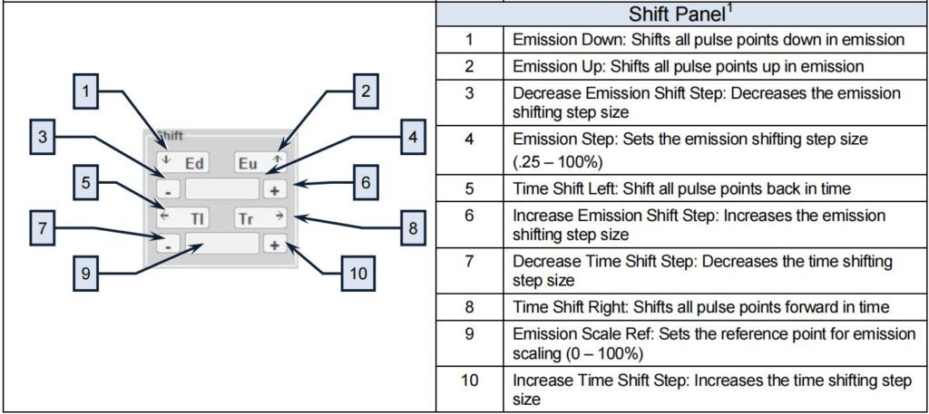
- In the Modulation panel, set a certain Emission Step percentage value, and then click Emission Shift Up or Emission Shift Down to introduce an emission offset to the pulse.
- In the Modulation panel, set a certain Time Step value, and then click Time Shift Right or Time Shift Left to introduce a time offset to the pulse. Please not that if the chart is exceeded, the pulse will be stored into Left or Right pulse buffers (“LB” and “RB” located on the top right of the pulse chart). The corresponding buffer will change to a green color if they contain pulse data.
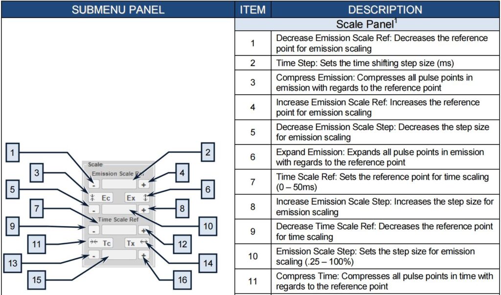
In the Modulation panel, set a certain Emission Scale Ref percentage value, it should be the effective zero point of your pulse to get the best result, for example if you are modulating a sine wave, you would set it to be in the center point. Also, set an Emission Scale percentage value then click Expand Emission or Compress Emission to scale effective emission with respect to the reference point.
In the Modulation panel, set a certain Time Scale Ref value, it should be the effective zero point of your pulse to get the best result. Also, set a Time Scale value then click Expand Time or Compress Time to scale effective time with respect to the reference point.
Note: Because of the sample time constraint, scaling can be unsymmetrical, and there could be a small range of ineffective scaling factors, all that is due to the sample approximation during the calculations. It is strongly recommended to save the original pulse prior to modulating a pulse.
Pulse Comparison
It is useful to compare and contrast different variations of a pulse, especially when performing modulation on a pulse. There are two ways to perform this comparison:
- Using two instances of PSG: At least one of which has to be started in an Offline session, then the two application windows can be compared side to side.
- The Snapshot Interface: This interface allows comparison of two pulses on the same chart:
- Click “Cap” in the Snapshot panel to capture (save) the original pulse
- Modulate or change the pulse
- Click “Cap” in the Snapshot panel to switch to the original pulse, any changes to the pulse here will be ignored.
- Click “Cur” in the Snapshot panel to switch to the pulse in progress, any changes to the pulse here will be saved.
- Click and hold “Duo” in the Snapshot panel to see both the original pulse and current modified pulse in the same chart each will have an identifying color.
- Click “Rst” in the Snapshot panel to reset the interface. Note: This will set currently viewed pulse as the current pulse and remove the pulse that is not in the current view.
Pulse Storage and Recall
On Laser
Note: This section requires connection to the laser. It is important to write pulses to the laser in order to use and activate them.
- First sketch a pulse, then from the top menu, select Laser Operations->Write Profile.
- Select a slot to write to then click Write Profile, then enter a name to save and click Write Profile.
- The pulse data will be encoded and transmitted to the laser for storage.
- To recall, select Laser Operations->Read Profile from the top menu, then select a slot and click Read Profile, the pulse will be fetched, decoded, and displayed on the chart. The displayed pulse may appear differently as any unused time in the chart will be removed as only the effective pulse width is saved.
- To delete a pulse, select Laser Operation->Delete Profile, select a slot then click Delete Profile.
Note: You will not be allowed to delete a pulse profile that has an attachment status greater than zero, which means that the pulse is used by an existing sequence or sequences. However, you will be allowed to overwrite them if you accept to bypass the warning. You will only be allowed to delete or make changes to a pulse if the pulse profile status is “Idle”. The “In Use” status identifies that the laser is configured with that pulse.
On Host PC
- In the top menu, select File->Save Profile, then select a name and path for the saved pulse.
- To recall, select File->Load Profile from the top menu then select the name and path of the file to load.
- Alternatively, you can use the CSV (comma-separated value) file version of the load and save from the main menu; the advantage is being able to modify the pulse data using a program like MS Excel. The following is the general format of a Pulse profile in a CSV format, consisting of tags and data values.
Required (header) tags:
[S] - Sample time in ms
[L] - Number of samples
[D] - Start of comma separated percent emission data
Optional tags:
[N] - Profile name (The file name is the default)
[C] - Comments, PSG will ignore, optional.
[M] - Pulse profile metadata
Example file (viewed in text editor):
[C]This is a test pulse profile,
[N]testProfile001,
[S]0.050,
[L]10,
[D]50.5, 60, 50, 60, 70, 80, 20, 0, 20, 30
Single Pulse Activation:
Note: This section requires connection to the laser.
- After storing a pulse to the laser, make sure the E-stop button is released on the laser and then press the green button to turn on the power supply
Note: Both Analog and Modulation modes must be set to “Off” to configure the pulse mode and are accessed in the Setup Submenu touch- screen. - On the laser touch-screen, select the Setup Submenu->Pulse Setting->Waveform Mode
- Toggle Waveform Pulse Mode to Enabled, and Single Pulse Selected (button displaying “Single Pulse”), then use the Up/Down arrows to select a specific pulse.
Note: If no pulse profile is saved the laser’s pulse profile list then “!! No Profiles Available!!” will be displayed. - Pulse Information/Preview (Optional)
- To get information about the pulse, click on the pulse browser button. This is the button with the name of the pulse. Once the information page appears, you can use the arrows to scroll thru all available pages.
- Click anywhere in the text space to go to the Preview page, here you can see the shape of the pulse.
- Click Return twice to go back to the Waveform page.
- Click Configure & Return.
It is important to configure the laser with the selected pulse (once) before usage. - After the configuration is complete, click Return twice to go back to the main page. Then click Emission, and then click OK to confirm and start countdown. The selected pulse will be emitted after the countdown. Click Emission again to clear the status.
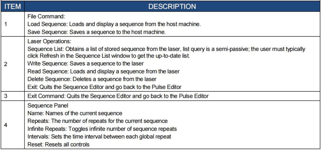
Sequence Editing:
Note: This section requires connection to the laser
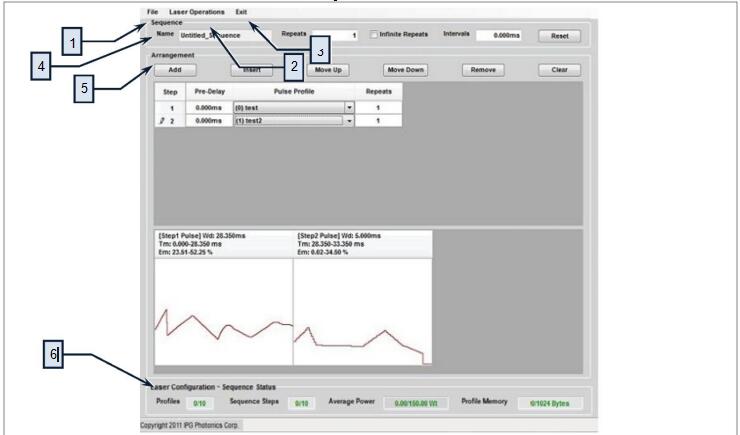
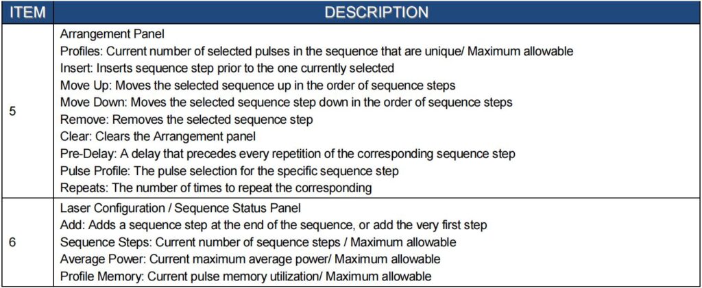
A pulse sequence is an arrangement of pulses, designed for finite or infinite repeats, and organized into steps, each step has an assigned an existing pulse, pre-delay and repeat amount. PSG will check each created sequence for any Average Power and other laser limitation violation, and will prompt the user to make adjustments.
Building a Sequence:
- Start the Sequence Editor by selecting it from the top menu
- In the Arrangement panel, click Add to add a sequence step
- In the added step, enter a Pre-Delay value, select a Pulse Profile and enter a number of Repeats
(number of times the selected Pulse Profile with Pre-delay must be repeated consequently). - Click Add again to add more sequence steps in the same fashion.
- You can set the number of sequence repeats by setting Repeats and Intervals in the Sequence panel.
- The preview of the sequence will be refreshed when changes are made to the pulse. Additionally, laser limitation violations are re-checked.
- A Blank profile is a special “null profile” space holder for introducing delay only as a sequence step.
Modifying a Sequence:
- In the Arrangement panel, highlight an existing step, then click:
- Insert to insert a new sequence step before the selected one
- Move Up to shift up the selected sequence step in the sequence order
- Move Down to shift down the selected sequence step in the sequence order
- Remove to delete the selected sequence step Sequence Storage and Recall
Note: This entire section requires connection to the laser.
On the Laser
It is important to write pulse sequences to the laser in order to use and activate them, in the Sequence Editor, select Laser Operations->Write Sequence, then select a slot and click
- Write Sequence, enter a name for the sequence then click Write Sequence.
- To recall, select Laser Operations->Read Sequence, then select a slot and click Read Sequence, the sequence will be fetched and loaded into the arrangement panel.
- To delete a sequence, select Laser Operations->Delete sequence, select a slot then click Delete sequence. Note: It is not possible to delete a sequence if the status is not “Idle”. When the status is “In Use”, it means that the laser is configured with that pulse sequence.
On the Host PC
In the top menu, select File->Save Sequence, then select a name and path for the saved sequence.
To recall, select File->Load Sequence from the top menu then select the name and path of the file to load.
Pulse Sequence Activation
- After storing a pulse sequence to the laser, make sure the E-stop button is released on the laser and then press the green button to turn on the power supply
Note: Both Analog and Modulation modes must be set to “Off” to correctly configure the pulse sequence mode. To change them for select Pulse Menu->Pulse Setting - On the laser touch-screen, select Pulse Menu->Pulse Setting->Waveform Mode
- Toggle Waveform Pulse Mode to Enabled, and Pulse Sequence Selected, then use the Up/Down arrows to select a specific pulse sequence.
- Pulse Sequence Information/Preview (Optional)
- To get information about the pulse sequence, click on the pulse browser button, the information page appears, you can use the arrows to scroll thru all available pages. Click anywhere in the text space to go to the Preview page, here you can see the shape of the pulses in the sequence; use the arrows to see the entire page. Click Return twice to go back to the Waveform page.
It is important to configure the laser with the selected pulse sequence (once) before usage. - Click Configure & Return. After the configuration is complete, click Return twice to go back to the main page. Then click Emission, and then click OK to confirm and start countdown. The selected pulse will be emitted after the countdown. Click Emission again to clear the status, this will also stop a pulse sequence if it is set to infinite repeats.
Remote Control Interface
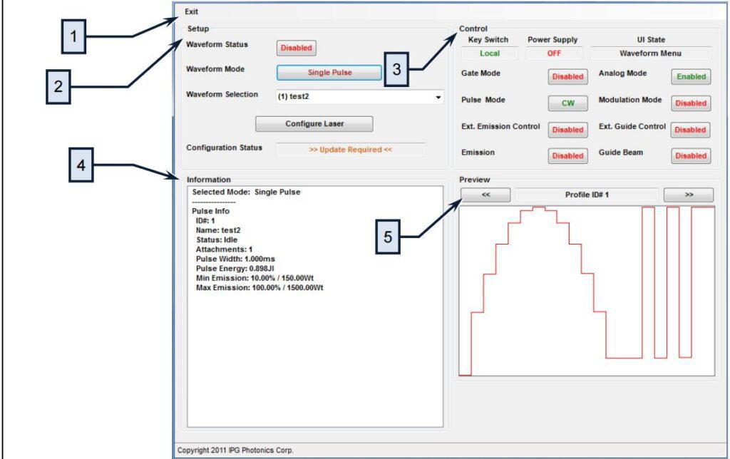
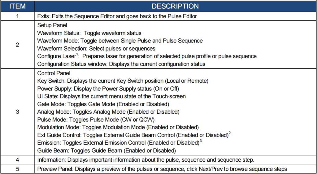
This interface is designed to provide remote control for PSG users, it is focused around the pulse shaping feature and it not meant to be a comprehensive control utility. Note: This interface will work simultaneously with the touch-screen panel.
To start the interface, select Remote Control from the top menu Use the Setup panel to enable the waveform (pulse) mode, select the pulse or sequence mode, select a pulse or sequence then configure the laser.
TROUBLESHOOTIING
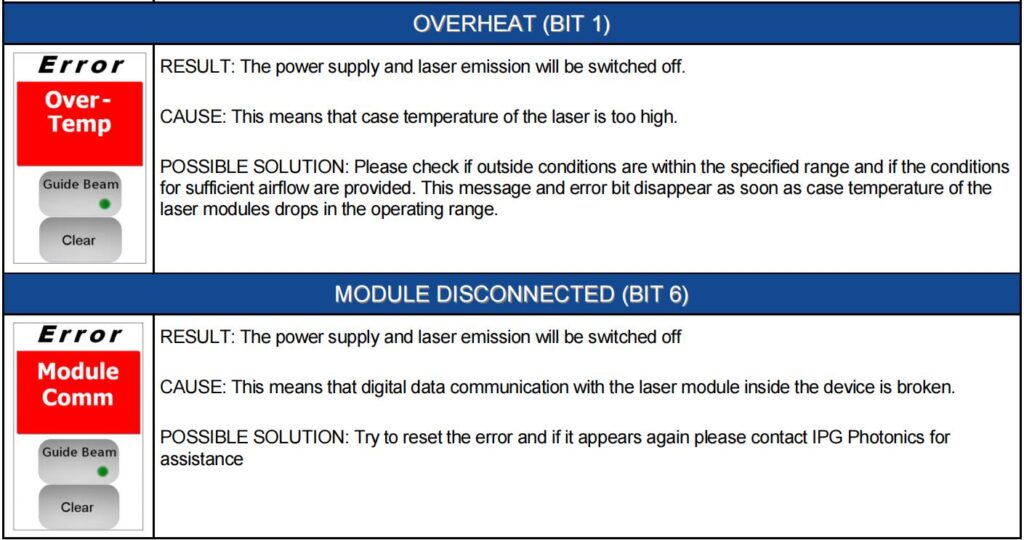
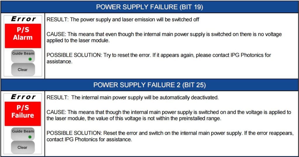
Error Messages on the Display and Status Bits
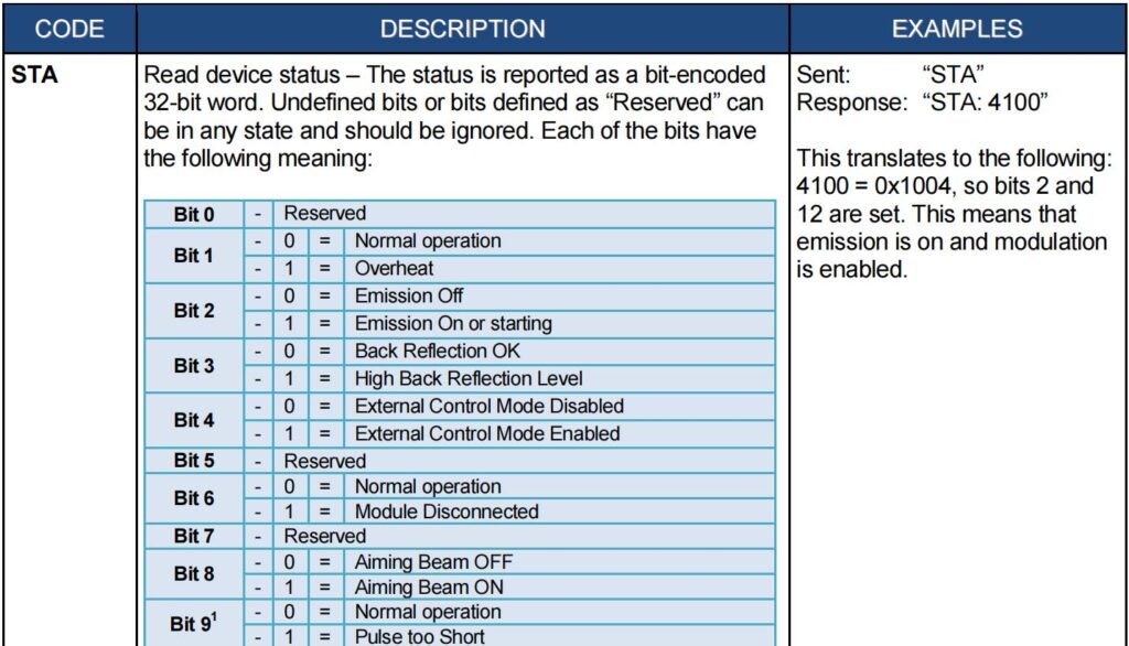
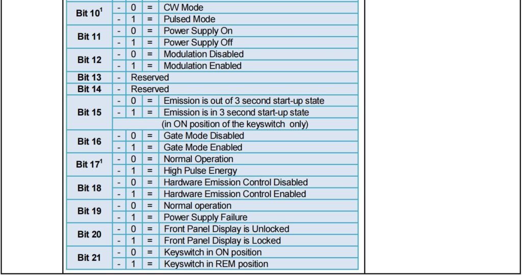
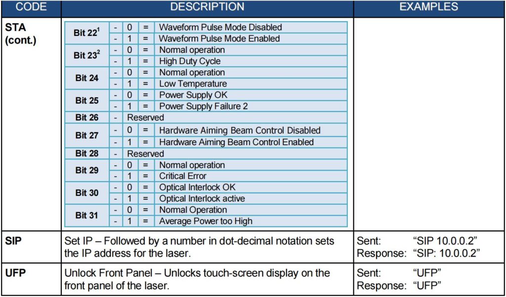
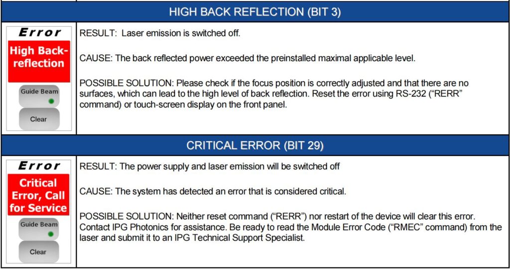
The following table describes the errors and possible solutions that are associated with the displayed errors on the touch-screen display or returned status bits via the RS-232 connection.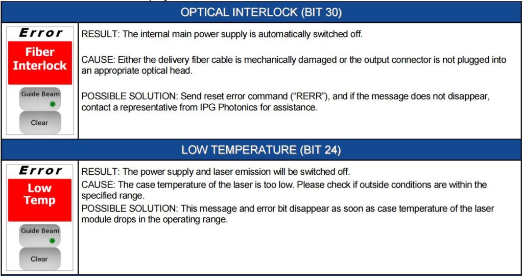
Learn more:
Learn more about our products, please visit and subscribe to our Youtube channel
