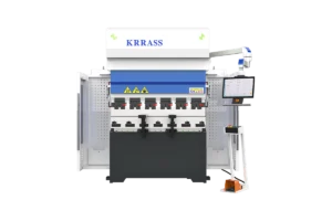
Hydraulic Press Brake adopts free bending technology, the movement stroke of the slider can be set by the corresponding dial, and the back gauge mechanism (dual axis) and the mechanical limit device of the slider can realize digital control.
When the working mode selection switch is set to the automatic operation position, the movement of the slider is as follows: step on the foot switch, the slider quickly drops to the switching point of the working stroke, and then uses slow down bending to form; reaching the set bottom stop After the point (at this time the foot switch has been released), it will automatically return to the top dead center.
Hydraulic Press Brake bottom dead center position control principle:
- The mechanical limit bottom dead center controls the bottom dead center of the hydraulic piston and the sliding block connected to it, which is limited by the limit screw sleeve. The position of the screw sleeve is driven by a worm, and the worm wheel only rotates without moving, so that the screw sleeve matched with the worm wheel can move up and down to change the position. The worm mechanism is equipped with a locking device. When the piston descends and contacts the upper end surface of the screw sleeve, the slider and the upper die are restricted, and the bottom dead center is controlled. The stroke position of the piston is detected by a displacement sensor.
 Stopper-servo valve type: When the piston rod descends, it hits the stopper (positioning screw), and the state of the servo valve is changed by the lever, thereby changing the oil supply to the hydraulic cylinder, so that the piston rod and the slider decelerate and stop. The stop is adjusted by the motor, and the position is detected by the encoder (or potentiometer). If this structure wants to control other movement transition points, or display the position of the slider at each moment, a displacement sensor must be installed.
Linear encoder-servo valve type: Hydraulic Press Brake uses a linear encoder to directly detect the position of the slider at each moment, and then controls the oil supply of the working cylinder through the numerical control system and the servo valve. It is equipped with two sets of linear encoders on the left and right.
The position of the left and right ends of the slider can be compared at any time through the control system, and the movement of the left and right cylinder pistons can be precisely adjusted through the left and right servo valves. Adjust, so that the tilt of the slider can be controlled to a very small value to ensure synchronous movement. It has no mechanical contact elements at all, so the depth of the upper mold wedge into the lower mold can be adjusted arbitrarily during the bending process.
The rotary motion of Hydraulic Press Brake is transmitted to the ball screw through the timing belt, and becomes linear motion through the nut, which drives the sliding plate and the stopper to move forward and backward along the guide shaft. An induction synchronizer is installed on the side of the carriage, and its fixed length is connected with the fuselage, and the movable ruler moves with the carriage to detect the displacement of the carriage and the stopper, and constitutes a closed-loop position control system. The mechanism has multiple stoppers.
Learn more about our products, please visit and subscribe to our Youtube channel
 Stopper-servo valve type: When the piston rod descends, it hits the stopper (positioning screw), and the state of the servo valve is changed by the lever, thereby changing the oil supply to the hydraulic cylinder, so that the piston rod and the slider decelerate and stop. The stop is adjusted by the motor, and the position is detected by the encoder (or potentiometer). If this structure wants to control other movement transition points, or display the position of the slider at each moment, a displacement sensor must be installed.