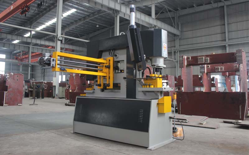
Hydraulic Ironworker is widely used in industrial cutting, cutting precision, simple and convenient. But do you know how to operate the combined punching and shearing machine? In fact, some preparations are necessary before the combined punching and shearing machine works.
Guide to the use:
Operation steps of Hydraulic Ironworker during test run The dial indicator is fastened to the slider, so that the dial indicator probe is placed on the inspection surface of the square. When the slider moves down, check in two mutually perpendicular offset upwards.
The difference in readings on the dial gauge is the perpendicularity error stroke length 25-50mm 0.04~0.08; in the hole of the fastening punch, a check rod is inserted precisely and a dial gauge is placed on the working table. Place the dial indicator probe on the appearance of the inspection rod; when the sliding block moves downward, it is inspected in two mutually perpendicular deflection upwards. The reading on the dial indicator is different; the value is the error of parallelism; stroke length≤25mm>25~50mm>0mm. Fasten the dial indicator on the outer end of the upper tool holder and make the dial indicator probe top;

On the vertical supporting surface that fits the lower blade; check when the upper tool holder moves down, the difference in readings on the dial gauge; that is, the error of parallelism. Shear thickness ≤10mm at 100mm stroke length; shear Thickness>10mm is on the stroke length of 100mm; the hole for fastening the punch on the punch holder, the parallelism of the middle line to the movement of the slider is 0.040.060.08;
The vertical bearing surface that is attached to the lower blade; the parallelism of the movement of the upper blade holder; 0.05~0.160.05~0.24 Note: When the upper blade holder moves downward, the distance between the two verticals that are attached to the upper blade and the lower blade ;Only increase the vertical bearing surface that fits the upper blade; parallel to the movement of the upper tool holder; put the dial indicator on the outer end of the working table, so that the dial indicator probe is on top;
On the vertical supporting surface that fits the upper blade; check when the upper blade holder moves down. The difference of the readings on the dial gauge; that is, the error of parallelism. Shear thickness ≤10mm in 100mm; stroke length: shear thickness>10mm; stroke length of 100mm: check both ends with a feeler gauge on a combined punching shear The gap between the blades;
The small difference is the error of parallelism. The working principle of the hydraulic combined punching and shearing machine The working principle of the shearing machine is that the upper blade is fixed on the tool holder, the lower blade is fixed on the lower bed, and the bed is equipped with a supporting ball to facilitate the feeding and movement of the sheet, and the back gauge.
The plate is used for the positioning of the plate material, and the position is adjusted by the position adjustment pin. The hydraulic pressure cylinder is used to compress the sheet to prevent the sheet from turning over during cutting. Shelters are safety devices to prevent accidents at work.
- Adjust the front baffle to close the back baffle to the lower knife edge, then put the template close to the back baffle, and fix the front baffle close to the template. Loosen the back baffle, remove the template, install the sheet material, and cut.
- Adjust the rear baffle to align the template support level with the lower knife edge, then close the rear baffle to the template and fix it, remove the template, and then install the sheet material for cutting.
- Adjust the angle baffle, first put the template on the table to align the lower knife edge, adjust the angle baffle and fix it, then adjust the back baffle according to the template, and use the angle baffle and the back baffle to position at the same time during the cutting process.
Precautions before hydraulic Ironworker operation:
- The lubrication of each transmission part should be sufficient, and each lubrication point should be refueled 2-3 times per shift;
- The cutting and punching die should be intact without cracking, and fastened firmly;
- The gap between the punch and the die hole wall should be uniform and meet the punching and shear requirements, and the punch configuration should slightly exceed the die hole plane;
- The operation steps when the equipment is electrically insulated and well grounded. The hydraulic combined punching and shearing machine is tested. Fasten the dial indicator on the slider, and make the dial indicator probe on the inspection surface of the square. When the slider moves down, check in two mutually perpendicular offset upwards. The difference in readings on the dial gauge is the perpendicularity error stroke length 25-50mm 0.04~0.08; in the hole of the fastening punch, a check rod is inserted precisely and a dial gauge is placed on the working table. Place the dial indicator probe on the appearance of the inspection rod; when the sliding block moves downward, it is inspected in two mutually perpendicular deflection upwards.
The reading on the dial indicator is different; the value is the error of parallelism; the stroke length is less than or equal to 25mm>25~50mm>0mm. The vertical supporting surface where the blade is attached; check when the upper tool holder moves down, the difference in the reading on the dial gauge; that is, the error of parallelism. Shear thickness ≤ 10mm at 100mm stroke length; Shear thickness> 10mm At 100mm stroke length;
The hole for fastening the punch on the punch holder, the parallelism of this middle line to the movement of the slider is 0.040.060.08; the vertical support surface that fits the lower blade; the parallelism of the movement of the upper tool holder; 0.05~0.160. 05~0.24 Note: When the upper blade holder moves downward, the distance between the two verticals that fit the upper blade and the lower blade; only the vertical bearing surface that fits the upper blade can be increased; the parallelism of the upper blade holder movement ;
Place the dial indicator on the outer end of the working table, so that the dial indicator probe is on top; on the vertical support surface that is attached to the upper blade; check when the upper knife holder moves downward. The difference of the readings on the dial gauge; that is, the error of parallelism. Shear thickness ≤10mm in 100mm; stroke length: shear thickness>10mm; stroke length of 100mm: check both ends with a feeler gauge on a combined punching shear The gap between the blades; the small difference is the error of parallelism.
Learn more about our products, please visit and subscribe to our Youtube channel


