How to Correctly Select Tools for a Press Brake
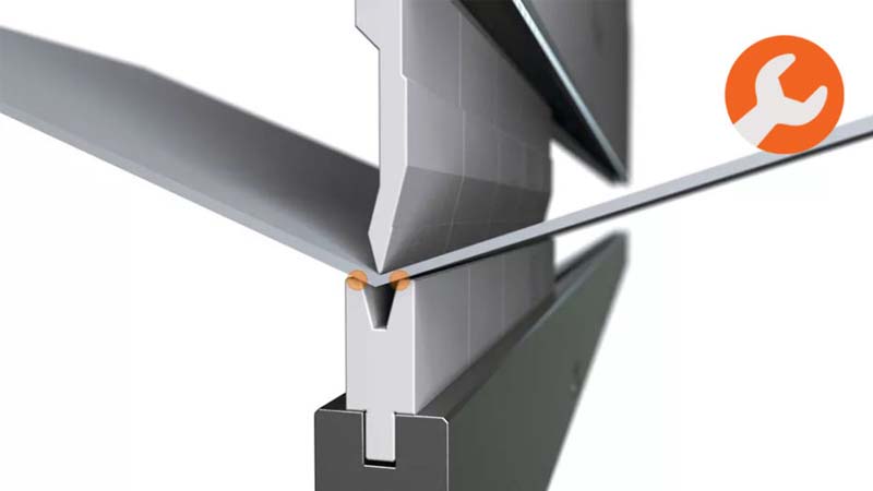
Many people believe that the press brake tools are some insignificant accessory in metal processing, where it is quite the opposite. Despite press brakes becoming multi-axial machine with high precision, it is the tools that come into contact with the metal during bending (see the image above).
The differences among the tools of RFA, Eueopean, American and new type of grip are being slowly vanishing. Many functions that are needed for high effective bending are now implemented into the various types of tools. Whatever style of tooling and grip you might choose, make sure it meets the minimum requirements listed below.
High precision. The tools shall be manufactured with tolerances in the range of 0.01 mm. This is crucial to achieve high detail accuracy without distortion or pinching during operation.
Sectioned instruments. These types of tools allow you to reach different length by combining pre-selected sectioned tools of different width. Smaller parts are safer and also much more convenient to work with.

(see Figure 1)
Quick release tools
The tool clamping system must be able to stably hold a different number of segmented tools in place until the locking system tightens them (see Figure 1).

Figure 2: Tools have to be held in place while the clamping mechanism is open.
Front loading (Rol2 type). You should have the possibility to load tools from the machine’s front side. This shortens the required time for their setup, as it is no longer necessary to loose precious time sliding all the tools from the side end of the press brake. With front loading, in most cases, the need for forklifts and cranes is also also eliminated.
Standard sizes. Tools of standard height can reduce the need for further machine adjustments when switching between jobs. The front arms, the heights of the back gauge and the safety systems remain in the same position. And due to the fact that the tools are made at the same height, you can add ready-made parts and be sure that they will fully match your existing tools.
Many press brake tools of high quality are made under metric standards. Such nominal size is 6,35 mm. V opening is 6 mm. All dimensions in the current article are rounded as value for maximum simplicity.
As you will notice, the text below focuses mainly on air bending, and it is for a good reason. The trend these days is to avoid coining and bottoming (between punch and die) and work with air bending instead, when that is possible. Keep in mind, however, that not all parts could be manufactured using classic air bending techniques.
Operators throughout the whole industry work with various tools in order to produce details of similar or even identical quality. Many operators fabricate details with the wrong tools for that because they lack access to the correct ones..They still manage to reach an adequate work process but often it is at the expense of productivity and repeatability.
Best practices when selecting press brake tools must have one main goal: to reach production of details with the highest quality possible for the least amount of time.
What kind of tools do you need exactly and why?
A maintenance production department will need and use a wider ranbge of press brake tools, compared to companies producing specific details, for example. Therefore, before stepping into specifics, you should first identify your needs and determine what budget you can spend on the tools.
For example, you may need additional tools in order to shorten the time needed for tools setup.
Die selection
Fo you to receive the best as per your budget, select minimum number of dies which shall cover the whole range of metal sheet thicknesses your company processes. Firms with basic knowledge, non-standard orders (applications) and restricted budget should aim to choose lower dies following the 8×2 rule.
First determine the range of metal thicknesses that you want to bend, as they can be between 0.5 mm and 20 mm, for example.
Then assess the smallest V die by multiplying the thinnest material by 8. For material of 0.5 mm, the smallest die will be: 0.5 × 8 = 4 mm.
Lastly, determine the biggest V die you need by multiplying the thickest material by 8. In this case the thickest material of 10 mm will need a die: 10 × 8 = 80 mm.
You have now defined the smallest and also the largest die that you need – respectively 4 and 80 mm. You then start with the smallest V matrix and double its size, in order to fill in what you need between them. In this case, this gives you an 8 mm matrix. Then you double it and you get 16 mm, then again to get 32 mm, and so on. In the end you have a minimum of six different holes in the V-die to bend a material of 0.5 mm to 10 mm thickness: 4, 8, 16, 32, 64, 80 mm.
Selection of a punch
To determine the minimum number of punches you need, you will also use the thickness of the bent material. For material 4.75 mm and thinner you can use a sharp offset knife with a radius of 1.016 mm. The sharp angle allows bending over 90 degrees, and the offset allows you to bend the material to form J shapes. When forming a material between 4.75 and 12.7 mm thick, a straight punch with a radius of about 3 mm is recommended, to handle the higher pressure.
Have in mind that for some applications, including those using thicker and highly bending-resistant material, when general industry bending standards are applied, the detail tends to bend, crack, or even split into two. This is connected to physics. The narrow tip of the punch exerts more force on the bending line; and when it is combined with a narrow hole in the V-die and the pressure increases. For specific details and especially when the thickness of the material is over 12.7 mm, it is best to consult your tool supplier about the recommended radius of the punch.
The „by 8“ rule
Usually you can select a V-die with the right opening using the rule „by 8“; this means that the die opening should be 8 times the thickness of the material which you are bending. To determine it, you multiply the thickness by 8 and select the die with the closest value. If the material has a thickness of 1 mm, the V-die has to be with an opening of 8mm (8х1=8); for a 1.25 mm thick material the V-die has to be 10 mm (1,25х8=10). This ratio provides the best result possible when bending. Most of the tables that are published are based on this formula.
Seems easy, doesn’t it? Yes but sheet material producers and draftsmen do not always follow the rule „by 8“ and the exceptions are plenty.
V-die Opening Determines the Radius
With mild steel air bending the inner radius is formed with approximately 16% of the V-die opening size. Therefore if you apply air beinding to a material on a V-die with 40 mm opening, the inner radius will be around 6 mm.
Let’s say for example that the drawing describes a 1.25 mm thick material. It is easy to multiply the material thickness by 8 and come to the conclusion that you need to use a V-die with 10 mm opening. Many sheet material producers and draftsmen though prefer to determine the inner bending radius by equaling it to the material thickness. What happens if the drawing requires an inner bending radius of 1.25 mm?
Again, in air bending, the inner bending radius is about 16% of the opening of the V-die. This means that a V-die with a opening of 10 mm will produce an inner radius of 1.6 mm. And then? Just use a V-die with a narrower opening. A die with an 8 mm opening will produce an internal bending radius that will be close to 1.25 mm (8 x 0.16 = 1.28).
The same approach applies when the drawing requires a larger bending radius. Let’s say you need to form a sheet material with a thickness of 1.25 mm with an inner bending radius of 5 mm – more than twice the thickness of the material. In this case, you will need a V-die with an opening of 32 mm, which will form an internal bending radius close to the requirements (32 x 0.16 = 5.12).
This approach has limits. For example, if you need to use a V-die with a hole that is 5 times less than the thickness of the material to achieve the desired internal bending radius, you will sacrifice the accuracy of the angle and will probably damage the machine and its tools and put yourself in dangerous situation.
Minimum length of the flange
When choosing a V-die, you must keep in mind the length of the flange. The minimum size of the flange that a V-die can form is about 77% of its opening. Therefore, an element that is formed with a V-die with an opening of 100 mm must have a flange of at least 77 mm.
Many technical draftsmen set elements with a short flange in order to save on material. For example, a 12 mm long flange for a material that is 3 mm thick (see Figure 3). According to the “by 8” rule, a 3 mm thick material requires a V-die with an opening of 24 mm. But a die with a 24 mm opening requires a flange with a length of 18.5 mm. Now what? Again, you can use a V-die with a narrower opening. For example, a die with an opening of 15.6 mm can form elements with a flange of 12 mm. (15.6 x 0.77 = 12,012)
This approach also has its limits. As with elements with a narrow inner radius, if the flange requires a die with opening less than 5 times the thickness of the material, then inaccuracies in the bending angle are observed, damages to the machine and its tools are possible and you put yourselves in a dangerous situation.

Figure 3: For the forming of this element with a thickness of 3 mm you would choose a die with an opening of 24 mm. But because of the length of the flange you have to choose a die with a narrower opening.
How to select the correct punch
For L-shapes, the rules are not strict. A punch with almost any shape will do the job. Therefore, when choosing punches for the several details forming, the L-shapes last should be considered last, because a punch with almost any shape will work with them.
When forming L-shapes, you use punches that can also form other elements instead of adding unnecessary tools to the inventory. Remember that when choosing a set of tools, the fewer they are – the better. In order to reduce costs, setup time and number of tools around the base (see Figure 4).

Figure 4
Other forms require more specific rules for choosing a punch. For example, when forming J-shapes, the rules are (see Figure 5):
When the upper flange is longer than the lower you must use a gooseneck punch.
When the upper flange is shorter than the lower, a punch of any shape will work.
When the upper flange has the same length as the lower one, you must use a tool with a suitable offset.

Figure 5: Some J-shapes require specific rules for choosing the right punch. When the upper flange is the same length as the lower one, you must use a tool with a suitable offset (left). If the upper flange is longer than the lower, you must use a gooseneck punch (right).
As you can see, the main factor in choosing the right knife is the possibility of unwanted contact of the part with the tools. To avoid this problem, bending simulation software can be helpful. In case you do not have access to such software, you can use the drawings of the tool manufacturer, where you can see their specific geometry and get an idea of the possibility of an unwanted collision between the tool and the detail (see Figure 6).

Figure 6
Rules for using tools for forming Z-shapes
In case you use common tools the the upper beam should make 2 strokes to form Z-shapes (see Figure 7).

Figure 7
The middle flange must be larger than half the total width of the V-die. Not from the width of its opening, but from its entire width.
The side flange must be shorter than the height of the V-die plus the distance between the tools.
When the middle flange is shorter than half the total width of the V-die, you will need a special tool to make the two bends in one go on the top beam ram. The advantage of these tools is that you do not need to turn the detail. The disadvantage is that you need about 3 times more bending force (see Figure 8).

Фигура 8
Rules for bending around opening and other types of processing
Any unsupported element in the V-die is subject to deformation; in the case of elements with internal openings and other treatments, this deformation is called swelling (Figure 9). When the openings that are close to the bending line are small, the corresponding swelling is also small. Also, most applications allow small deformations, so there is no specific rule as to which V-die is best suited for these situations.

Figure 9
When flanges, openings and other types of processing are close to the bending line, dies with additional moving elements can be used. They rotate and support the part throughout the bending process, thus eliminating deformations.
Figure 9 shows identical details with openings near the bending line; the one in the foreground – with the obvious deformations – is formed by a simple V-die; that of the background is formed by a die with additional moving elements.
Height of the punch when forming boxes with specific size
The height of the punch is essential when boxes with 3 and 4 sides. In some cases, short punches can form boxes with 3 sides if the element is extended at the very end of the tools, so that one of the formed sides protrudes from the side when bending the final (third) side. If you are forming a box with 4 sides, you must choose a punch as high as the diagonal of the box (Figure 10).
Minimal punch height when bending a box =
(Box depth / 0.7) + (Upper beam thickness / 2)

Figure 10
A bending and hem combination
Bend-hem tools can form bendings and hems without needing to change tools, as you can see in Figure 11. Remember that if you need a hem thickness greater than 3 mm, you will need special tools to compensate the need of higher power.

Figure 11
Here the selection of die opening follows the same rules as with standard tools. The 30-degree pre-bend for the hem requires a slightly longer flange – 115% of the opening of the selected die, due to the sharp angle. For example, if you are forming a material using a die with an opening of 10 mm, you will need a flange with a length of 11.5 mm.
Scratch-free details
Almost all V-dies leave scratches on the detail because the metal is pushed into the die during bending. In most cases, scratches are minimal and acceptable, and the use of a die with a larger radius of the opening angles (R) can reduce their appearance (see Figure 12).

Figure 12
In cases where even minimal scratches are unacceptable, for example when bending painted or polished materials, you can use special rubber bands to avoid them (see Figure 13). Making scratch-free details is extremely important when producing details for aviation and aerospace, because it is difficult on visual inspection to distinguish between scratch and crack.

The simpler, the better
Press brake and their precise tools can reach high precision level nowadays. And when working with the correct tools and quality material you can achieve a flange with a specific angle and a specific inner radius. Recall that air bending forms an inner radius as a percentage of the V-die opening, so using the right tools is very important. When making details with multiple radii with a small tolerance of deviation, the cost of tools increases. And with tools, the time needed to change them increases, which then increases the cost even more.
With this in mind, producers can limit the number of tools and operations required if they follow a few simple rules when designing details:
The inner radius should be 1.5 times the thickness of the material.
The length of the flanges should be at least 6 times the thickness of the material. This also applies to openings in the detail. It is due to the fact that openings must be at a distance of 6 times the thickness of the material from the bending line.
Exceptions to these rules, of course, exist and each of them brings different complications along. You can use a V-die with a narrower opening to bend a narrower radius or a shorter flange, but if you bend too narrow a radius you risk cracking along the bending line, exceeding the tonnage provided for the tool or the press brake. You can bend a narrower offset, but this again requires a special tool and considerable force to obtain it.
If the details does not require short flange, a Z-form or a narrow radius, why complicating the process?
Follow these simple rules and you will improve tha angles quality, you will reduce the setup time and the prices of the tools.


