FSCUT8000 is a bus system dedicated to high power application. Most of the high-power fiber laser cutting machines produced by KRRASS use this system.
Chapter 1 Product overview
1.1 Product description
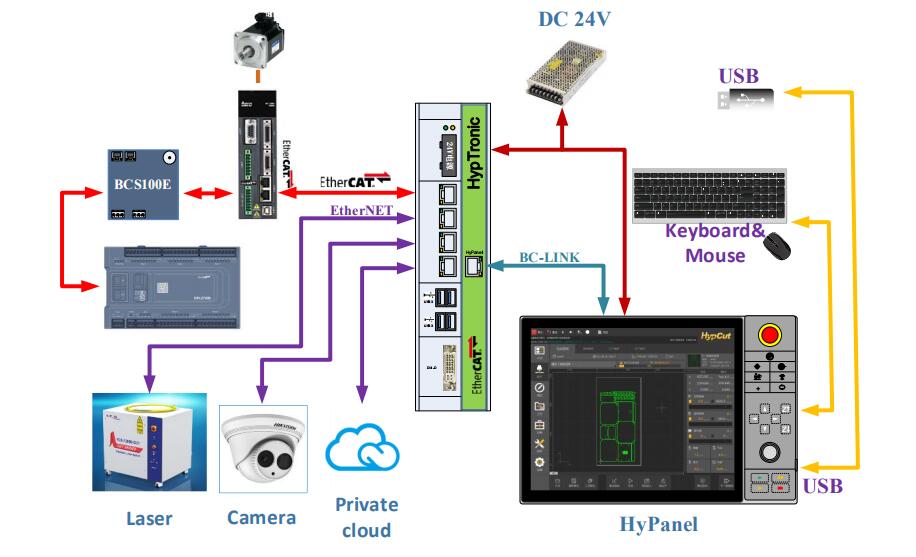
FSCUT8000 system is developed based on EtherCAT bus and integrates BClink single line display transmission technology. It is a perfect solution for high-end laser cutting CNC machine tools. This manual is for fitting and installation guide only. For software operation please refer to Hypcut user manual.
1.2 Product view
1.3 FSCUT8000 spare parts list
The FSCUT8000 bus CNC system consists of the following components: HypTronic industrial host computer, HyPanel700 touch screen, HPL2720E expansion board, BCS100E height controller and connection cables.
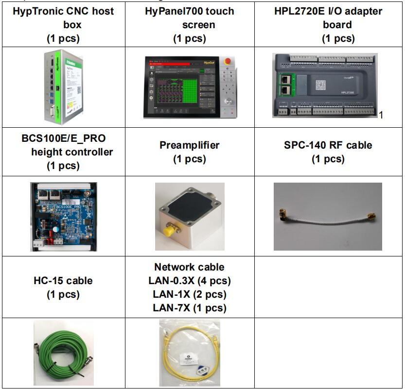
Note: BCS100E/E_PRO means there is BCS100E or BCS100E_PRO for option;
Chapter 2 Wiring instructions
2.1 HypTronic wiring instructions
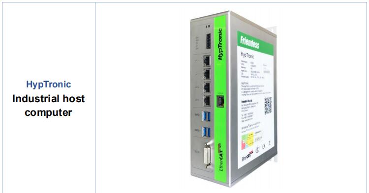
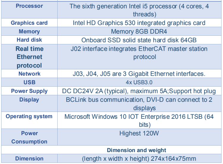
HypTronic is an industrial host computer based on EtherCAT and BClink technology. The robust and exquisite metal shell design provides good grounding and strong anti-interference ability.

2.1.1 Interface layout
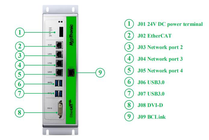
The detailed interface layout of the HypTronic terminal is shown in the following figure:
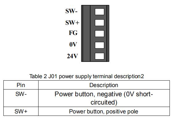
2.1.2 J01 terminal description

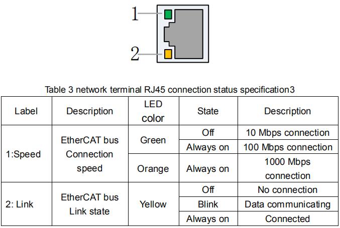
2.1.3 J02 EtherCAT communication terminal description
J02 terminal is EtherCAT interface.
2.1.4 J03/04/05 standard Ethernet terminal description
J03/04/05 are standard RJ45 interface. It can be used to connect network devices such as network cameras, lasers with network communication, switches, etc.
2.1.5 J06/07 USB terminal description
J06/07 are standard USB3.0 interface, can be used to insert USB devices.
2.1.6 J08 DVI terminal description
J08 is a standard DVI-D terminal, can be used to connect display with DVI interface and realize dual monitor control. Not used by default.
Note: This DVI is not used by default, and only supports DVI-D mode, cannot use DVI-VGA adapter to connect the display of VGA interface.
2.1.7 J09 BClink terminal description
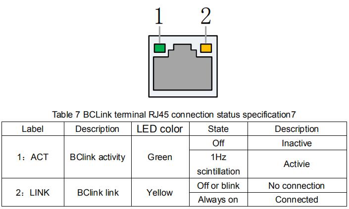
The BClink interface uses standard RJ45 connectors to transmit display signals and USB signals to the HyPanel display via a single wire. The advantages are simple wiring and strong anti-interference ability.

2.2 HyPanel wiring instructions
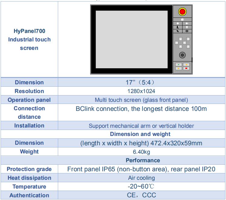
Hypanel is an industrial LCD panel integrated BClink technology, and integrated with a USB keypad.
- Intuitive, quick operation with multi point touchable glass front panel
- Excellent product design of widescreen with industry standard.
- Capacitive touch screen for industrial applications
2.2.1 Interface layout
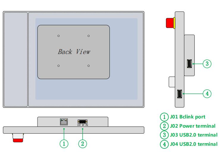
The detailed interface layout of the HyPanel terminal is shown in the following figure:
2.2.2 J01 BClink terminal description
The BClink interface uses a standard RJ45 connector to transmit display signals and USB signals to the HyPanel display through a single wire.

2.2.3 J02 power supply terminal description
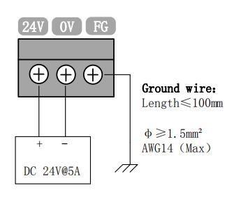
The power terminal is connected to the positive and negative pole of the DC 24V switching power supply, which supplies power to the HyPanel screen.
FG must be reliably connected to the earth, and the ground wire should be as short and thick as possible. Ensuring the reliable grounding of the screen shell can not only improve the stability of the system, but also prevent the damage of the screen or interface caused by external static electricity or surge.
2.2.4 J03/04 USB terminal description
Hypanel provides 2 USB2.0 interfaces (J03 and J04). J03 interface is dedicated to the wireless key mouse receiver.J04 interface is dedicated to the use of the U disk import and export files.
2.3 HPL2720E wiring instructions
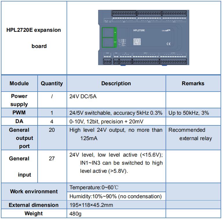
HPL2720E is an I/O expansion board based on EtherCAT bus, which supports the peripheral resources required by FSCUT8000 high power cutting system.
2.3.1 Interface layout
The detailed interface layout of the HPL2720E terminal is shown in the following figure:
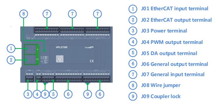
2.3.2 J01 EtherCAT input terminal description
EtherCAT network cable input interface, accessing standard RJ45 network cable;
2.3.3 J02 EtherCAT output terminal description
EtherCAT network line output interface, accessing standard RJ45 network cable;
2.3.4 J03 power input terminal description
Notice:
- 24V and 0V are respectively connected to the positive and negative poles of the DC 24V switching power supply. FG must be reliably connected to the earth, and the ground wire should be as short and thick as possible.
- All wiring terminals can only be plugged and removed as shown in the right picture above. It's able to wiring and not plug the terminal.
2.3.5 J04 PWM output terminal description
HPL2720E has 1 PWM signal used to control the laser power. PWM signal level is 24V or 5V as option. The duty cycle 0%~100% is continuously adjustable with the highest carrier frequency 50KHz. The output of the signal is shown in the following figure:
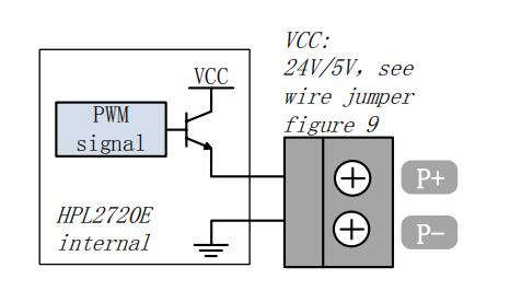
Note: P+, P- signal has enabled solid state relay, no need external rely!
2.3.6 J05 DA output terminal description
There are 4 analog outputs of 0~10V in HPL2720E.4 DA can be assigned as laser peak power and gas proportional valve control signal in "Installation setting" of Hypcut.

2.3.7 J06 general output interface specification
There are 20 high level 24V outputs from OUT1~OUT20The output ports can be assigned as "Height controller", "Laser", "Cutting head", "Cutting gas", "Alarm", "Exchange table", etc., in Installation setting module on Hypcut.
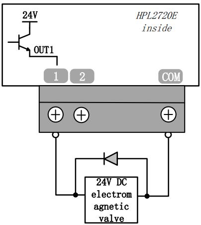
Note: It can only be connected to DC, and the output current of each circuit must not exceed 125mA.
If AC load is needed, please connect the external relay.
2.3.8 J07 general input interface specification
No dedicated input set in HPL2720E, and all input ports can be configured as limit and origin signals.
The NO and NC mode of limit and origin signal can be modified in Installation setting in HypCut. When set as normally opened, input is valid when conducting with 0V. When set as normally closed, the input is valid when it is disconnected from 0V.
The typical connection of photoelectric switch, as shown in the following figure, must be NPN 24V photoelectric switch;
Typical connection of mechanical contact switch is shown below;
The typical connection of magnetic switch, as shown in the following figure, must use NPN type 24V magnetic induction switch.
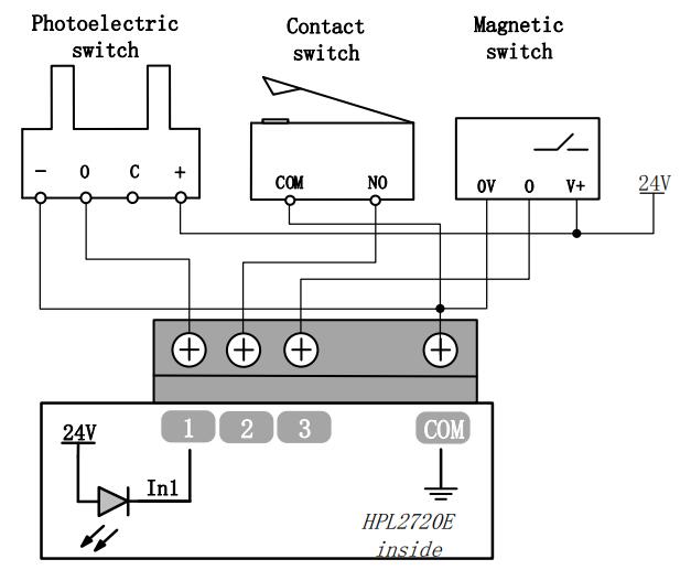
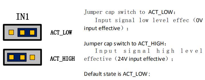
IN1~IN3 can adjust the polarity of effective level by hardware jumper.
2.4 BCS100E wiring instructions
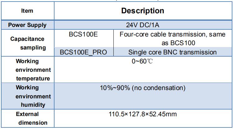
BCS100E is a standard height controller based on EtherCAT bus.BCS100E_PRO is specially designed to support Precitec cutting head, perfectly support the entire Precitec series cutting head.
2.4.1 Interface layout
The detailed interface layout of the BCS100E/PRO terminal is shown in the following figure:
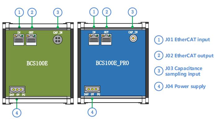
2.4.2 Power interface specification
The outer shell of the machine is the negative pole of the capacitance to be measured. In order to ensure the stable operation of the measuring circuit, the FG foot of the power interface must be reliably connected to the outer shell of the machine (using short and thick grounding wires). The outer shell of the preamplifier must also be well connected to the outer shell of the machine. The specific index is DC impedance less than 4 ohms, otherwise the actual follow up performance may be poor.

2.4.3 Sensor interface specification
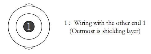
The BCS100E sensor interface specification is shown in the following figure:
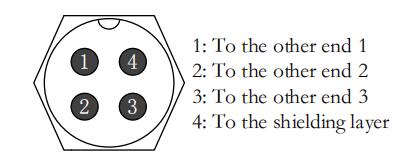
The BCS100E_PRO sensor interface specification is shown in the following figure:
2.5 Cutting head wiring instructions
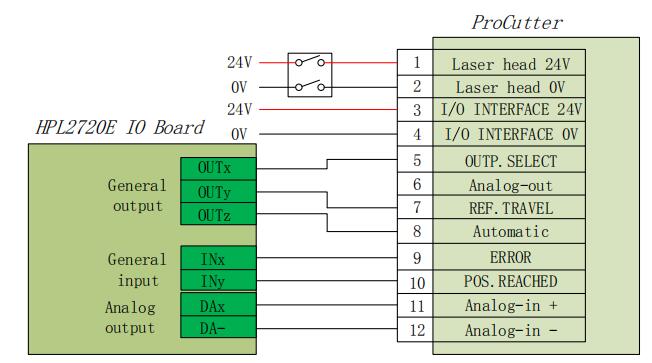
2.5.1 ProCutter cutting head connection
The connection of the ProCutter cutting head is shown in the following figure:
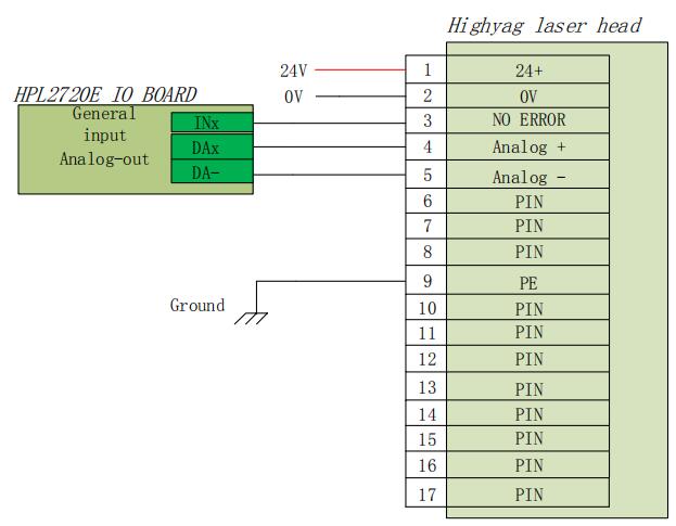
2.5.2 Highyag cutting head connection
The connection of the Highyag cutting head is shown in the following figure:
2.6 Laser wiring instructions
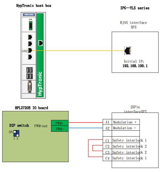
2.6.1 IPG-YLS series network communication wiring diagram
IPG-YLS series lasers all can be connected to lasers in this way:
2.6.2 IPG- German version of non-network communication wiring diagram
The connection of the Highyag cutting head is shown in the following figure:
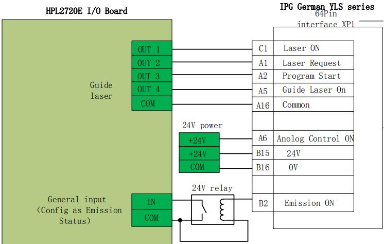
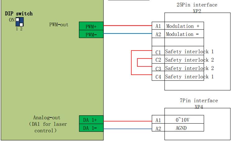
2.6.3 IPG- US version of non-network communication wiring diagram
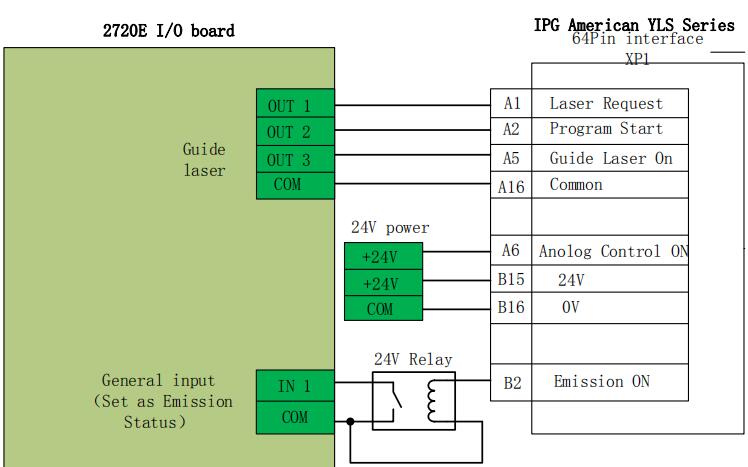
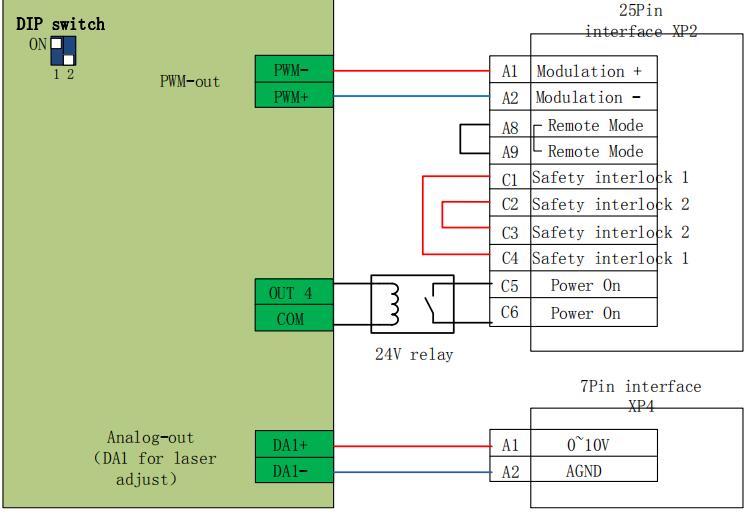
2.6.4 RayCus laser serial communication wiring diagram
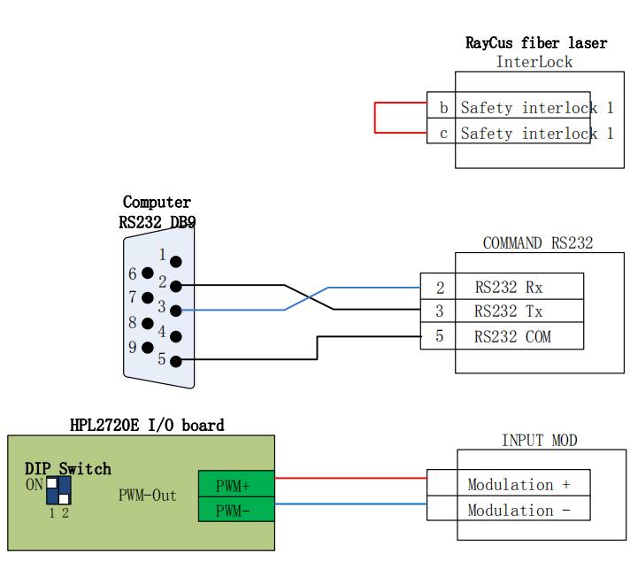
Note: Because the latest HypTronic host box has cancelled the RS232 interface. If connected with Raycus laser by serial communication, it is suggested to use a separate USB for RS232 module.
2.6.5 TRUMPF laser serial communication wiring diagram
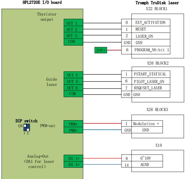
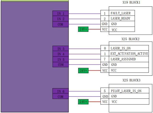
2.6.6 Serial communication wiring diagram of Rofen laser
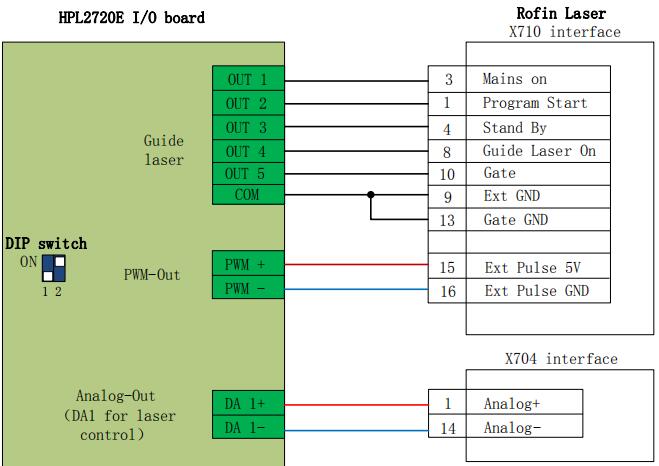
Chapter 3 Quick start
3.1 System recovery
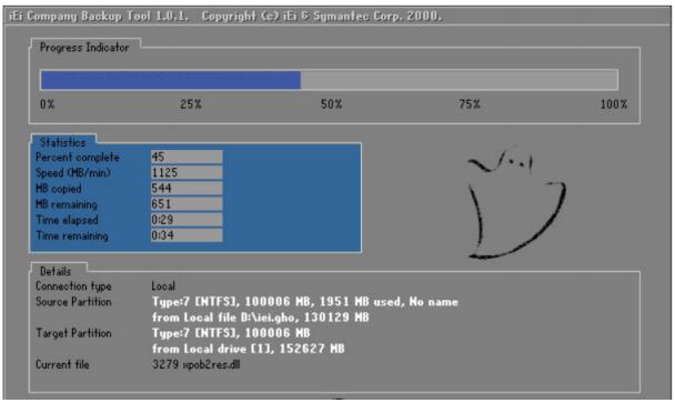
If the system get virus or too many programs slow down the system, please do the system restore as following steps:
- HypTronic restart
- Press "F3" shown in figure below

- Input “1” at the following interface and press enter

- Automatic enter recovery interface

- Restart the system, recovery is completed.
Chapter 4 Attention
4.1 Wiring precautions
4.1.1 Guide for routing of towline cable
1. When releasing the cable from the coil, it is necessary to prevent the cable from twisting (it needs to be laid along the tangent direction) and to straighten the cable.
This work should be carried out before laying the cable, providing a period of stress release for the cable. Because the manufacturing process cannot fully guarantee that the cable is straight and without any distortion, the printed markings on the cable surface rotate along a tiny spiral.
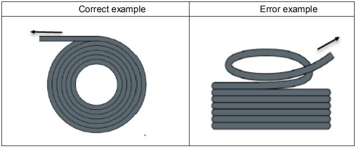
2. The cable is not allowed to twist when it is installed in enclosed space.
The twist during installation may lead to premature damage of the core strand.This effect is gradually strengthened in the operation of the cable, resulting in the phenomenon of back-twisting, which eventually leads to core breakage and failure.
3. Cables must be laid side by side in the towing brackets. Isolating pieces should be used to separate cables as far as possible. The gap between cable and isolator, separator or its adjacent cables should be at least 10% in diameter.

4. The cables should be installed symmetrically according to the weight and size of the cables. The larger diameter cables should be placed outside. Smaller and lighter cables should be placed inside. Cables can also be placed from inside to outside in order of decreasing size. One cable should be laid on the other cable without the use of isolation panels.
5. For vertical suspension tow chains, more free space must be left in the vertical bracket because the cable will be lengthened during operation. After a short period of operation, it is necessary to check whether the cables are running along the central area and adjust them if necessary.
6. For self-supported drag chain structure, cables are fastened to moving points and fixed points. It is necessary to use the appropriate cable support provided by the towing chain supplier. When operating at high acceleration, the applicability of cable strapping is very limited. It should be prevented to tie multiple cables together. Cables should not be fixed or tied to the movable parts of the tow chain in any way. The gap between fixed point and bending motion should be wide enough.
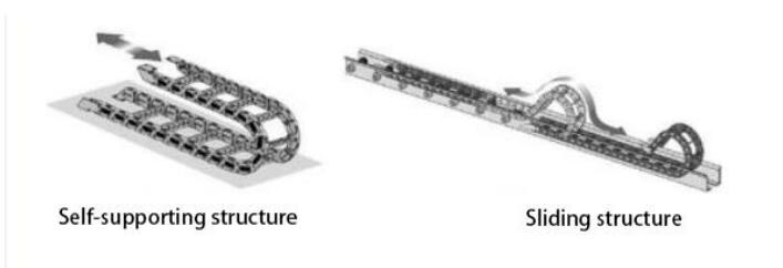
7. For sliding towing chains, we suggest that cables should only be fixed on moving points. A small cable protection area needs to be set at the fixed point.(refer to the assembly instructions of the drag chain supplier).
8. Make sure that the cable moves along the center area under the required bending radius. Do not apply tension to the cable (do not pull too tight), otherwise the friction inside the tow chain will lead to cable sheath wear;Do not let the cable loose too much in the tow chain, otherwise it will easily lead to wear and tear between the cable and the inner wall of the tow chain, or entanglement with other cables.

9. If the cable is not running smoothly, you can check whether there is any distortion along the longitudinal axis during operation. The cable should rotate slowly at a fixed point until it runs smoothly.
10. In view of the absolute size of cables and towing chains, their length variation characteristics are quite different. In the first few hours of operation, the cable stretched naturally. For towing chains, it takes many hours to run this phenomenon. Such a big difference can be solved by regularly checking the installation location of cables. We recommend regular inspections, once every three months in the first year of operation, and then at each maintenance time.
The contents include checking whether the cable is completely free to move within its proper bending radius and adjusting it if necessary.
4.1.2 Specification for machine tool wiring
1. Wiring specification for power supply
(1) Strong electricity
- Strong and weak electricity is strictly separated.
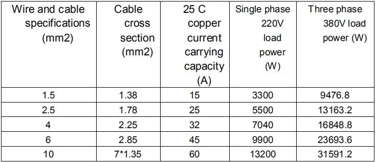
The power line is selected according to the size of the power line diameter. The attached is the cable diameter and power comparison table.

- Strong current plus short-circuit protector, filter and other auxiliary devices.
(2) Weak current (take DC24V as an example)
- The power positive and negative pole wiring colors are distinguished, for example:
The red line is connected to the positive pole, and the blue line is connected to the negative pole. - Larger interference loads, such as servo and solenoid valves, are supplied separately from the controller.
2. Specification for earth wire connection
- The ground wire adopts standard yellow green double color line.
- There are some high frequency signals (PWM, pulse, encoder, capacitance signal, etc.) in the laser cutting machine tool. It is suggested to use multi-point grounding.
- Galvanized earthing screws for machine tools and earthing with special earthing wires. The resistance between the grounded metal main body and the main grounding point should not exceed 0.1 ohms.
3. Specification for signal (control) wiring
- Signal line color: Such as black.
- The signal line is selected according to the power size.
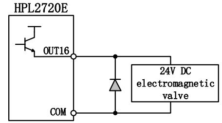
- DC 24V solenoid valve is recommended. Absorption circuit is added at both ends of solenoid valve, that is, a continuous current diode (attention direction, current resistance value, voltage resistance value) is connected in parallel at both ends of solenoid valve, as shown in the following figure:

- It is recommended that the digital signal (PWM) shield layer be grounded at two ends and the analog signal (DA) shield layer be grounded at one end.
Single ended grounding can avoid low frequency current noise on shielding layer. Double-terminal grounding can effectively eliminate high-frequency interference. If the transmission cable is long, multi-point grounding is recommended to ensure that the shielding layer is equipotential. - The resistance of the cutting head connected by the amplifier to the shell of themachine tool is not more than 1, and the resistance of the grounding point to the electric cabinet is not more than 6.
4. Other specifications
- Each wire is marked and marked clearly and accurately.
- Line and line are arranged in parallel. No crossover is allowed. The arrangement of wiring harness and line pipe should be straight.
- When choosing Friendess wires, choose the appropriate type of wire according to the layout space, do not accumulate hovering.
- All wiring must be reliable and not loosen to prevent ignition.
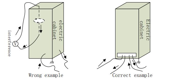
- Wiring avoids formation of loops and prevents antenna effects. A current loop consisting of a signal source, a transmission line, a load is equivalent to a magnetic field antenna. As shown in the figure below, the wrong way is on the left side and the right connection is on the right.

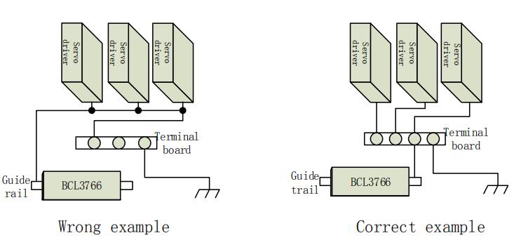
- The recommended connection is star-structure connection, and serial connections are not recommended.

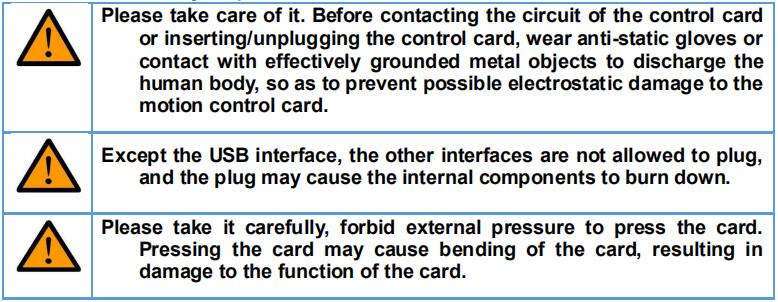
4.1.3 Product assembly requirements
Chapter 5 FAQ
5.1 Host unable to enter system
- Check whether the power port of the host and display is loose, and whether the 24V voltage is normal?
- If the host can turn on, check whether the display power is loose or not. Is the voltage normal?
- If the display is normal, the system cannot be entered, and the system may get virus. Following the following procedures:
- Use win+R to manually boot explorer.exe loading;
- Restart host to see if it is normal to enter the host interface.
- If you enter the host interface, please use antivirus software to remove the virus. If you are still unable to enter, please restore the system.
5.2 Touch screen does not display
- Check whether the display power supply port is loose, and the 24V voltage is normal?
- Check if the BClink interface is inserted.
5.3 Systemic virus
- Operate according to system restore specification.
5.4 No encryption card on boot.
- Check if there is abnormal USB equipment and uninstall the abnormal USB device.
Chapter 6 Product dimensions
Chart 1 Hyptronic figure 1
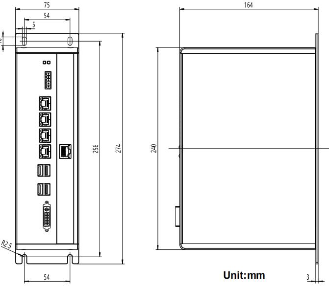
Chart 2 HPL2720E dimension figure2
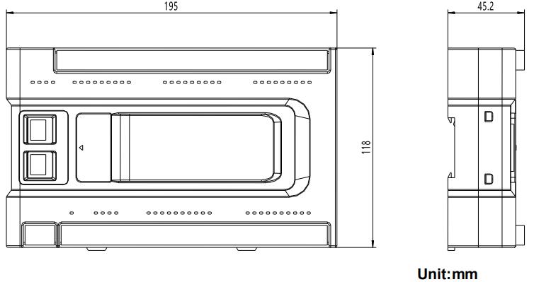
Chart 3:Hypanel dimension figure
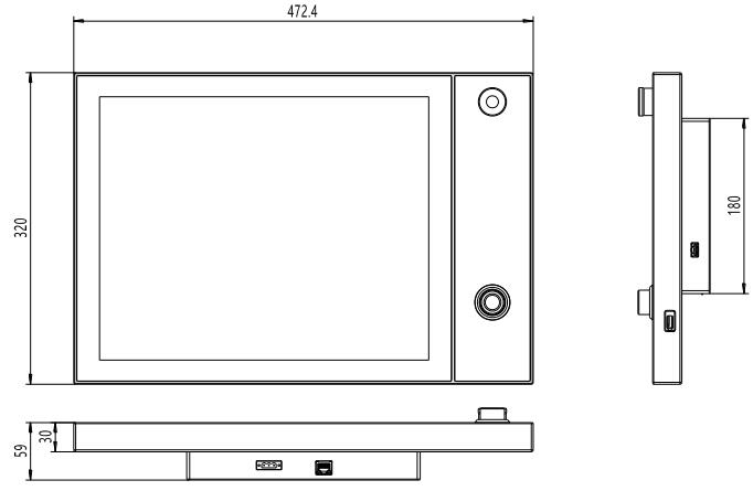
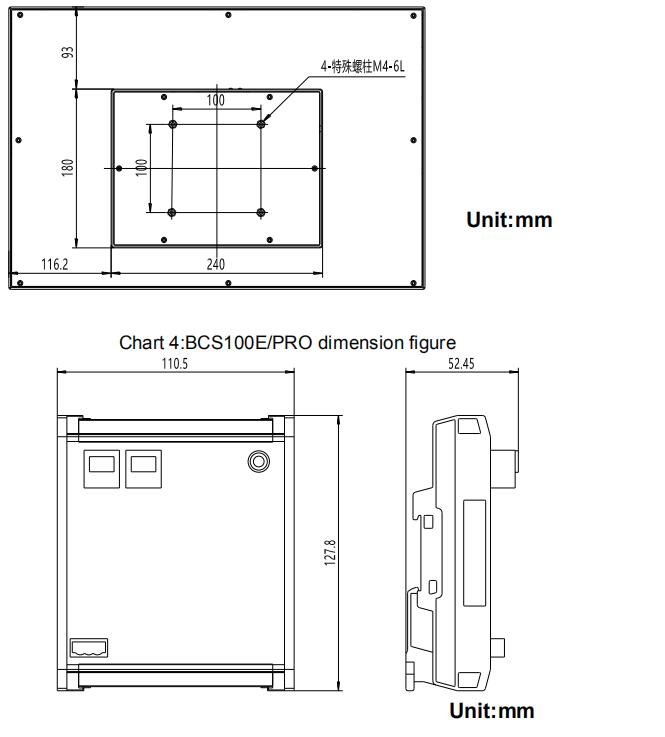
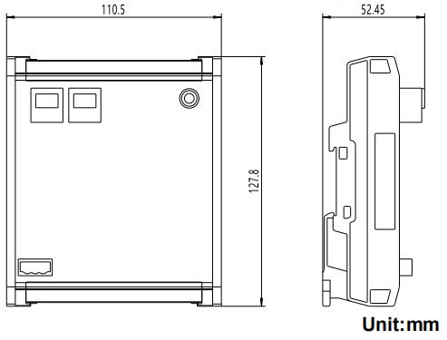
Chart 4:BCS100E/PRO dimension figure
Learn more about our products, please visit and subscribe to our Youtube channel


