Click the button to select the Part you want to view:
Part. 1
Part. 2
Part. 3
Part. 4
Part. 5
Part. 6
Part6: General Problems
6.1 “Motion control card initialization fails” pops up when open Cypcut
1.“desktop” of computer→ click right in “my computer” →“attributes” →“hardware” → “device manager”. Click “operation” → “Scan for hardware changes”.
See whether there is motion control card, as shown below: If BMC1604V2 motion control card can be found in device manager, please try reopening Cypcut software.
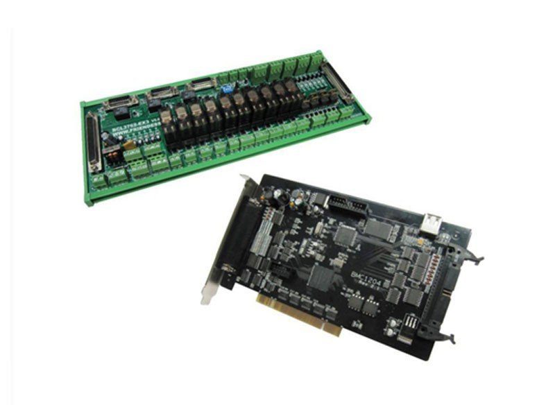
2.Observe the blinking state of 2 small lights (LED7,LED8)on top of BMC1604V2.
The position of lights is shown as below:

3.If LED is one flash and one flash (alternately flashes), which indicates BMC 1604V2 card is normal. Maybe PCI slot is bad contact. We suggest reinserting board card or replacing PCI slot after computer switches off.
6.2 Pulse equivalent setting
The system defines that pulse equivalent is the command pulse count sent after 1mm movement.
The maximum pulse frequency of BMC1204 motion control card is 3Mpps.
Assume the maximum operating speed designed by the system is 1000mm / s. Then the pulse equivalent for each axis should not exceed 3Mpps / 1000 = 3000 Pulse / mm.
Under the permitted circumstances, we suggest set the pulse equivalent in 1000 ~ 2000 Pulse corresponding to per 1mm, and thus pulse sequence can be more continuous. Please try not to set the pulse equivalent as 200Pulse / mm or less.
Set pulse equivalent of X axis and Y axis as the same as possible, which is helpful to reduce truncation error calculated by the system.
6.3 Graphics processing is quite slow or pause
- In Cypcut, we use node mode to observe this graphic. If nodes are too many and graphics consist of many micro-segments, please perform curve smoothing on graphics and then process them.
- Check whether the unreasonable delay is set or not, or the unit is misread, for example, set 200ms as 200s.
- If the Z-axis has pause during the movement of lifting and descending, please check the program version of BCS100 height controller. If It’s BCS100 V2.0 height controller, please make sure the program was upgraded to the version of V802 or later.
- Opening laser after blowing for a long time, please check the serial communication of laser is available.
6.4 Corner burning
- If machine allows, improve FIR frequency and reduce time of acceleration and deceleration.
- Properly increase turning precise parameters, and make high-speed smooth transition in sharp corner with Bezier curve.
- Modify the mapping way, processing the circle overcut by the example as shown below.

- Modify power curve, turn down laser power when speed declines.
- Add cooling points on the corner, further processing after blow to cool for a period with light off.

6.5 Laser not emitting light
1. Check whether the laser setting is correct or not
- Determine correct laser configuration in the platform configuration tool (YLS series of IPG has difference between German version and American version)
- Determine whether serial port or Ethernet communications is applied and communications port is configured correctly.
- Determine whether the DA signal control is applied to control the peak power, DA is selected correctly.
- PWM-enabled and light-enabled is configured correctly.
2. Check the output signal of PWM and DA
- Modify the output value of DA and PWM in the interrogation window of CypCut software (file—interrogation window). Use multi-meter to test whether DA of BCL3762 terminal block and voltage of PWM output port is normal or not.
- If PWM output voltage is too low or the DA signal has no output, try to replace another interface of PWM or DA.
- If it’s hardware failure, please contact our technical support or apply for repair.
3. Check connection
- Check the connection of PWM, serial cable and laser control signal lines.
- Make sure serial cable use a shielded cable. 2 pin and 3 pin need to be cross.
4. Check laser
- Use the matching software coming with laser to do self-checking and to check light change, and to judge whether laser is working normally.
- In the case of serial communication, not allow to open multiple software to communicate with lasers at one moment.
- In the case of no serial port communication, you can click debug mode to view the sent instructions and the response of the laser.
6.6 Scan cutting setting instructions
6.6.1 Function brief introduction
CypCut6.3.495 later version adds new functions: Scan cutting, also called fly cutting. Scan cutting of regular array pattern (suit for sheet metal) and naturally successive cutting of arc can be achieved by this function, thus greatly enhancing the processing efficiency. Function buttons are shown in the area of the following figure.
6.6.2 Function description
1. Linearly same-direction-grouping scanning: After the rectangular array is selected, set as linearly same-direction-grouping scanning. During the actual cutting process, rectangular will be divided into four direction scanning movement. Move of the middle section is not acceleration and deceleration shift, with just opening and closing the light.
2. Naturally successive cutting of arc: After the circle array is selected, set as naturally successive cutting of arc. Actual cutting is the same as connecting all circle or arc with a straight line. There’s no acceleration and deceleration during processing, with just opening and closing the light.
6.7 Pitch compensation

As long as conditions allow, be sure to select “Use Z signal”, which will greatly enhance the accuracy of homing origin. BMC1604V2 motion control card matched with CypCut provides encoder input to each axis, to extremely ensure accuracy.
Please select the direction X and Y axes home origin based on machine actual design. The direction of homing origin directly determines in which quadrant of the coordinate system the machine will run. If you select the “negative direction” to home origin, then the machine will run in the range of positive coordinates, otherwise the machine will run in the range of negative coordinates.
If possible, please repeatedly home origin by CypCut, then measure the accuracy of homing origin by laser interferometer. Usually, the position of every homing origin does not differ more than 5 microns.


6.7.7 Operation sequence
- Mechanism return to origin;
- Set interferometer to get parameter;
- Set parameter on optical adjustment interface of cypcut, generate interferometer locating procedure.
- Use interferometer to measure error, get mechanism date;
- Import interferometer data in the tool of platform configuration and save it;
- Mechanism return to origin;
- Use interferometer to measure error again, verify the result of pitch compensation;
6.7.8 General problem solving
1.The compensation without changing before and after Return to origin after compensation, than compensation data will be valid.
If set the pulse equivalent as 200Pulse / mm or less, compensation data will not be valid.
2. Error doubled after compensation
If it is found that the shape of the forward and reverse error curve is almost no change after compensation, but the value almost doubled and the distance between the two curves is also doubled (That is, reverse interval), it is likely that the sign of error value is reversed. In this case, click the “error value inversion”, which can make compensation accuracy is greatly improved.
The reason for the problem is that the error data file provided to CypCut does not contain the measured value, while only contain the error between the measured value and the theoretical value. And the error may be found by the measured value subtracting the theoretical value, or the theoretical value subtracting the measured value, leading to import data which has two possibilities.
The pos file formats generated by API XD Laser Interferometer, as well as the lin file format generated by light moving OptoDyne, contains both the theoretical value and the measured value. So the question of error sign when reading would not arise.
3. Reverse interval doubled after compensation
If it’s found that the pros and cons have been improved after compensation, but the effect of improvement is not obvious, and the reverse interval has increased even with doubling trend, it is likely that the forward data has been compensated to the reverse, and the reverse data has been compensated to the forward. At this moment, please click the “exchange of pros and cons” to make the positive and negative data (that is, red and green curves) reversed.
When the data sign tested by interferometer is inconsistent with the actual stroke range sign of machine tool, this situation most likely happens. The positive direction determined by interferometer is the direction of coordinate increasing, opposite to the direction of the machine coordinate increasing. CypCut has automatically handled this situation as much as possible, but it still cannot guarantee that all cases can be handled automatically.
4. The positive and negative curve is symmetrical after compensating.
If it’s found that positive and negative curves symmetrically change after compensation, the most likely reason is that the sign of forward error and reverse error is opposite, one of which is correct, and the other is wrong. This condition is considered to be very rare. In order to reduce the difficulty of customers understanding, CypCut has blocked the button which deals with this situation. If this happens to you, please manually make the error of forward or reverse reversed before importing, and then import. Or contact us to help solve.
Learn more about our products, please visit and subscribe to our Youtube channel


