Click the button to select the Part you want to view:
Part. 1
Part. 2
Part. 3
Part. 4
Part. 5
Part. 6
Part5: Motion Effect Optimization
5.1 Infer inertia ratio and machine characteristics
Machine inertia ratio is a key indicator we measure the machine characteristics.
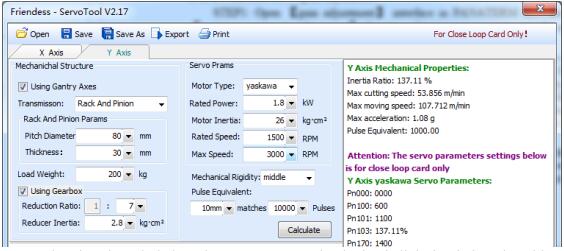
Using Servo Tools of Friendess, we can very easily calculate the inertia ratio of the machine for each axis. Servo Tools can be downloaded in http://downloads.fscut.com/.
As shown below:
When inertia ratio is less than 200 percent, the device is light loaded, and enables high-speed cutting.
When inertia ratio is greater than 200% but less than 300 percent, the device is medium loaded, lose some precision during high-speed cutting, and need to appropriately reduce processing acceleration and FIR frequency.
When inertia ratio is greater than 300% but less than 500 percent, the device is overloaded, unable to achieve high-speed cutting.
When inertia ratio is greater than 500%, there are serious design flaws, servo is difficult to complete setting in a short time.
The maximum supported machine cutting speed, the maximum air shift speed, and the maximum acceleration can also be simply calculated by Servo Tools. These three parameters can be directly applied to control parameters in the software.
Experienced users can also accurately calculate the inertia ratio through testing software coming with servo.
Notes: the servo parameters calculated by Servo Tool is only used for the closed-loop card. Users of open-loop card, please set servo parameters based on position mode.
5.2 Servo gain adjustment
5.2.1 Basic requirement
First, debuggers should be familiar with servo and can use professional servo software to debug servo. For example, Panasonic servo comes with PANATERM testing software and Yaskawa servo comes with SigmaWin+ testing software. This can simplify debugging.
5.2.2 Panasonic servo gain adjustment
STEP1: Open 【gain adjustment】 interface in PANATERM software. Open【real time automatic adjustment】 function of target axis, to automatically estimate inertia ratio.
STEP2: Rigidity is set as conservative value. For example, it can be set as level 13 first. Then click to move this high-speed axis with CypCut software. Observe whether axis is with abnormal sound and vibration, etc. Raise rigidity slowly. When the axis is with abnormal sound or vibration, level 1~2 should be declined to guarantee system stability. The final level should not be level 10 and more than level 20. If it’s dual-drive shaft, it starts moving only after modify two pairs of drive shaft parameters.
STEP3: After rigidity of X axis and Y axis is tested, set rigidity level as the same
level to guarantee response of two axes are the same. The smaller rigidity is standard.
For example, X axis is level 19 and Y axis is level 16. Finally, set X axis and Y axis as level 16.
STEP4: Close 【real time automatic adjustment】 and save parameters.
5.2.3 Yaskawa servo gain adjustment
Yaskawa servo debugging is similar with the Panasonic. However, there is some difference. The difference is as below:
- SigmaWin+ cannot be used to dual-drive axle ratio estimation, and advanced auto-tuning. Inertia ratio calculation tool, Servo Tool can be downloaded from the official website of Friendess to roughly calculate the inertia ratio for each axis. Advanced users may also accurately calculate the inertia ratio, based on a change of acceleration torque and acceleration time, by themselves.
- We suggest closing Pn140 model tracking function.
- We suggest closing Pn170 free adjustment function.
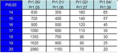
- Yaskawa servo does not introduce rigidity and can set the following parameters based on Panasonic servo rigidity: Pn102 position loop gain: Correspond to pr100 of Panasonic.
- Pn100 speed loop gain: Correspond to pr101 of Panasonic.
Pn101 speed loop integral time constant: Correspond to pr102 of Panasonic.
Pn401 Torque filter time constant: Correspond to pr104 of Panasonic. - The table is as below, and you should pay attention to unit and decimal point.
The unit of Yaskawa speed loop integral time constant, Pn101, is 0101 ms, while the one of Panasonic is 0.1 millisecond.
5.2.4 DELTA servo debugging experience
Delta servo debugging can also refer to the rigidity table of Panasonic. The reference method is shown as below:
The parameter P2-00 KPP is the equal of the position loop gain of Panasonic.
Though its unit is rad/s, actually, It’s 1/s. For example, when the P2-00 KPP= 90, it’s the same as Pr100=900 of the position loop gain of Panasonic.
5.3 Motion Control parameter adjustment
5.3.1 Motion control parameter introduction
FSCUT2000 Fiber Laser Cutting Control System mainly opens these four types of motion control parameters, such as speed, acceleration, FIR frequency, corner and circular accuracy, to users to adjust. Other sports-related parameters have been optimized internally without needing user settings. The meanings of these four parameters are shown as below:
[wptm id=40]
5.3.2 Adjust processing acceleration
The speed of high-clicking can be set as high as possible, such as 500mm / s.
When complete a click, moving distance is required to be long enough, in order to ensure that speed can be accelerated to the setting value.
Observe the torque curve of click movement by the servo debugging software.
For example, if the maximum torque is less than 80%, appropriately increase the processing acceleration; if the maximum torque is higher than 80%, appropriately reduce the processing acceleration.
Adjust the acceleration, until the maximum torque nearly is 80%. Generally, the processing acceleration withstood by lead screw is not more than 0.5G. Rack and pinion generally is not more than 2G.
5.3.3 Adjust move acceleration
Directly fill the maximum acceleration calculated by ServoTool software, or appropriately increase the move acceleration on the basis of processing acceleration, for example, set as 1.5 to 2 times of the processing acceleration. It’s required that the maximum torque of the servo is not more than 150%, and the mechanical structure does not occure significant deformation and vibration under this acceleration. Screw affordable air movement acceleration generally is not more than 0.5G. Rack and pinion generally is not more than 2G.
Adjust the FIR frequency as high as possible in the case of no affecting the accuracy. It is required the corner does not generate waves when cutting a rectangle, polygon and star. It can be set according to experienced value of the following table, Or debug the FIR frequency within the upper and lower two ranges after determining a processing acceleration. These two parameters, processing acceleration and FIR frequency, must be matched, with never transferring one value quite large and another value quit small among these two parameters.
Learn more about our products, please visit and subscribe to our Youtube channel
