Click the button to select the Part you want to view:
Part. 1
Part. 2
Part. 3
Part. 4
Part. 5
Part. 6
Part3: Platform Configuration
3.1 Installation and operation
When you install CypCut software, your default selection is platform configuration tool.
Click “start”- “all programs”- “CypCut software for laser cutting”- “platform configuration tool” (the icon is ![]() ) to operate platform configuration tool software.
) to operate platform configuration tool software.
“CypCut software for laser cutting” in the path is the name of software. Different customers have different software names.
3.2 Password Input
Before operate platform configuration tool, password box will appear as shown below:
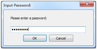
Input password 61259023 and click “OK”, and you can start configuration of platform parameters.
Note:
Users should do parameter configuration based on actual configuration of cutting platform and wrong configuration may lead to unpredictable consequence!
In the platform configuration, the orange background color represents the input port configuration, the green background color represents the output port configuration.
3.3 User interface
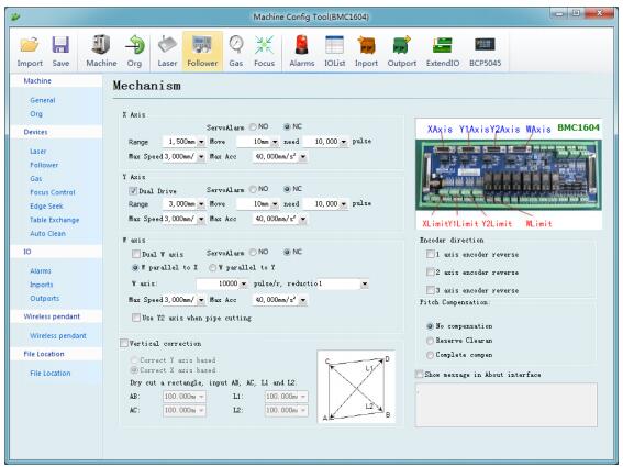
Main interface of platform configuration tool is information overview; The left and the upper convenient buttons are for entering various parameters setting page; green selected box as shown in the figure above is convenient button for controlling laser, height controller and adjusting auxiliary gas. Click left “config file” button to locate Data file.
Double click information overview to enter into parameters setting page for current information, such as: double click “mechanism” to enter machine setting page.
Click “Load” button to open existing configuration files; Click “Save” button to save information.
Note:
- Data files include various configuration information of CypCut software.
- Data files backup function is in CypCut software —- “File” —- “parameter backup”.
3.4 Mechanism configuration
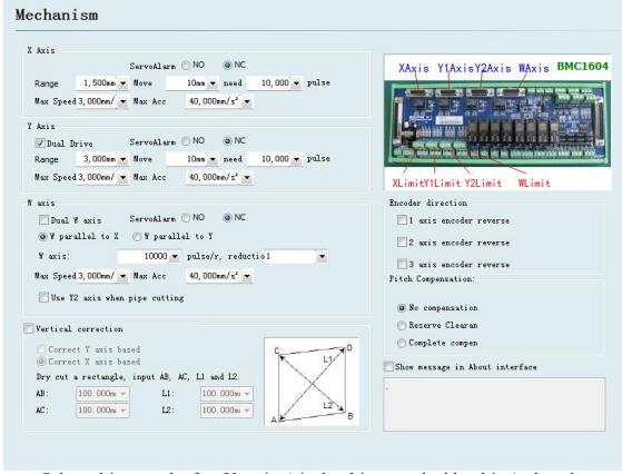
Select drive mode for Y axis (single drive or double drive), based on mechanical structure, and then configure information of rotation axis.
X axis range: Width of rectangle on CypCut painting interface. After start software limit protection, max motion range for X axis.
Y axis range: Height of rectangle on CypCut painting interface. After start software limit protection, max motion range for Y axis.
Pulse equivalent: Pulse count sent for 1 mm motion. Count automatically by actual motion distance and pulse count, and millimeter value can be set as four digits after the decimal point. Pulse equivalent= pulse count/ millimeter value.
Servo alarm: Select servo alarm signal logic, or close servo alarm feedback. Speed limit: limit max speed and acceleration for CypCut software.
Pitch Compensation: Error compensation for Interferometer data.
Verticality correction: When installation of X axis and Y axis is not 90o, the deviation can be eliminated through “Verticality correction”.
3.5 Return to origin configuration
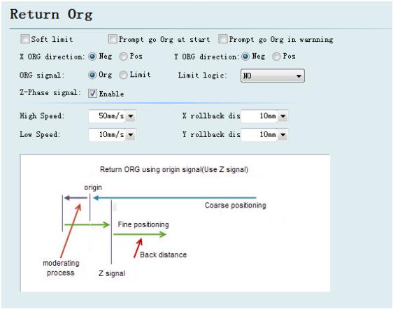
Forced open software limit: Enforce to open software limit function, and prevent users from manually switching the software limit in the master interface of CypCut.
Prompt user to return to origin after booting: Prompt the user to do the operation of returning to the origin each time you open the software.
Return to origin in the way of alarm: Prompt the user to do the operation of returning to the origin in the way of alarm each time you open the software.
ORG direction: Different type can select different rollback to origin direction.
Back to origin direction determines which quadrant tool coordinate is in. For example, if X axis and Y axis select negative back to the origin, tool motion is in the first quadrant.
ORG signal: if users select limitation signal, origin switch can be replaced by limitation switch in the process of back to origin to realize coarse positioning.
Z direction signal: whether to use Z direction signal and sampled signal determines specific process of back to origin. The system will show a whole process on an image based on different back to origin way.
Fine speed: As shown in the green section of the figure, approach the origin slowly and 10mm/s is recommended.
Coarse speed: As shown in the blue section of the figure, approach the origin fast and 10mm/s is recommended.
Rollback distance: A distance for back in the motions of back to origin can ensure distance of mechanical origin leaving a distance from position limit switch.
Limit switch logic: Set logic of X, Y, Z axis limit, and origin signal.
3.6 Laser configuration
CypCut provides different lasers configuration for YAG, CO2, IPG, Raycus, and SPI, other fibers, and different fiber types correspond to different parameters.
3.6.1 CO2 laser configuration
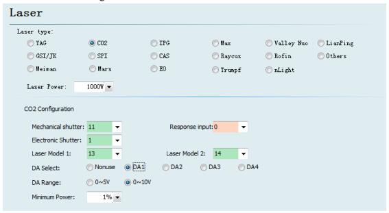
Mechanical shutter: Set output port for controlling mechanical shutter.
Electrical shutter: Set output port for controlling electrical shutter.
Response input: Set output port for response signal after opening mechanical shutter.
Laser Model: Set laser form as continuous wave, gate pulse and strong pulse through laser model 1 and laser model 2.
DA Select: 1604V2 card provides 2 interfaces of analog quantity and any interface o f output power controlling laser.
DA Range: Set analog quantity range of controlling laser power.
Minimum Power: Set minimum limit for pulse power.
3.6.2 IPG laser configuration
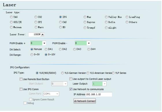
PWM enable signal: Select a relay output port as PWM enable switch, which can avoid laser leakage or wrong trigger under modulation mode.
DA Select: 1604V2 card provides 2 interfaces of analog quantity. Any interface can control laser peak power. Don’t use this port when using serial port or n e t w o r k remote control.
IPG fiber laser configuration:
Remote start button: After starting IPG remote control, CypCut software will monitor the state of lasers in real time and can operate lasers by means of communication. Motions, such as Emission, Guide beam, Current, etc, are realized. After selecting this option, DA port will be not available.
IPG remote control provides serial port and network, so users can set serial port or network IP address based on actual condition. If communication of PC, laser and BCS 100 applies network communication, please pay attention to don’t repeat segment. For example, if height controller segment is 10.1.1.x, and then laser can be set as 192.168.1.x. From the perspective of system stability, network is recommended.
If using serial port communication, please pay attention to shell and shielding layer of serial port connector must be ground connection.
3.7.2 Not use BCS100 network height controller
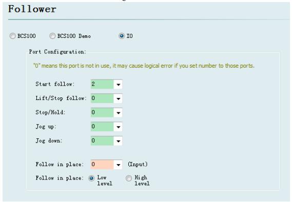
CypCut also supports input/output port to control height controller of other brands. Users can set the output port of following, rise (close following), stop (Hold), move up and down by clicking, and input port of following signal, by themselves.
Follow: open the input port for following.
Retract: set output port for raising (close following).
Stop/ Hold: Set output port for stopping Z axis motion.
Jog up: Set output port for manually controlling Z axis raising.
Jog down: Set output port for manually controlling Z axis declining.
Tracking in place signal: Set input port for collecting and following signal.
Tracking in place signal level: Set effective mode for controlling signal level.
Notes: If port is set as “0”, it means it is not available. If there is no this signal, please don’t set randomly, otherwise it may cause logical error!
3.8 Auxiliary gas configuration
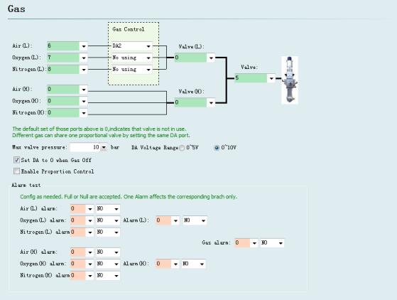
Valve: Set the total output port for auxiliary gas correspond to switch.
High pressure valve and low pressure valve: Set the output port for high pressure gas and low pressure gas.
Air Port: Set output port for air selection.
O2 Port: Set output port for oxygen selection.
N2 Port: Set output port for nitrogen selection.
DA Pressure: Users can select two interfaces of analog of 1604 card to regulate auxiliary gas pressure
Alarm detecting: Choose input port for gas alarm.
3.9 Alarm configuration
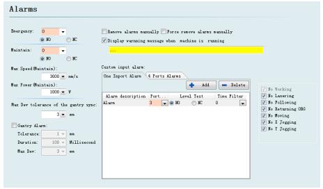
3.9.1 Operating warning
When the machine operates, the title bar will display a yellow warning message. You can customize the display.
3.9.2 Dual-drive excessive deviation alarm
If X or Y axis of the platform structure apply a bilateral drive, you can set up a dual-drive shaft position excessive deviation alarm. If the dual-drive error reaches a certain value (allowable deviation) and continues for a certain period of time (duration time), the system will generate a “dual-drive shaft position excessive deviation alarm”. If the deviation reached the maximum deviation value (maximum deviation) in a moment, the system will immediately generate an alarm.
3.9.3 Emergent stop button
Configure input port for emergent stop button, and here emergent stop is an input signal. If input port is active, emergent stop alarm will be generated.
3.9.4 Inspection switch
After input port is active, the system will enter a mode of inspection, the maximum speed and maximum power will be restricted.
3.9.5 Customized input alarm
Users can add other types of alarm in “customized input alarm” and input alarm name in alarm description. Select port number and level detection type corresponding to alarm. General customized alarms include lack-voltage alarm, excessive temperature alarm, laser head collision alarm, etc.
3.9.6 Allowable maximum deviation when gantry synchronizatio
The allowable maximum deviation, after enable the function of gantry synchronization.
3.10 General input
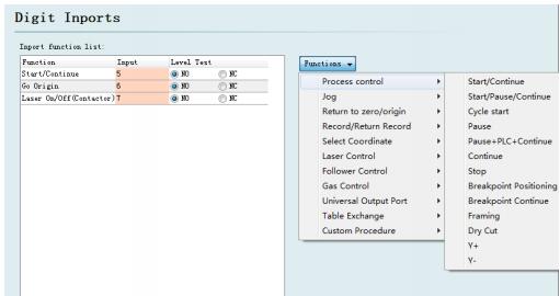
Click on the “Function Select” button, users can select the function name of the input port in the drop-down list, and then configure the corresponding input port and level detection.
Some functions of switching are divided into four sub-items, such as a laser switch, as shown below:
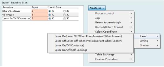
Each instruction is shown as below, please select according to your needs.
It’s in the following table:
[wptm id=41]
3.11 General output
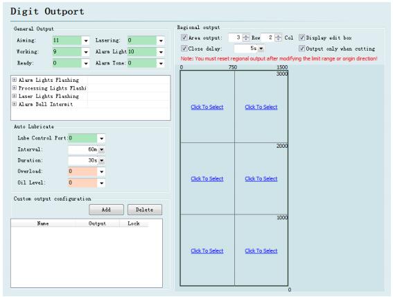
Aiming: Set output port for beam switch.
Laser instructions: After port configuration, corresponding indicator light will blink during lightening.
Work instructions: After port configuration, corresponding indicator light will blink when processing.
Alarm light: After port configuration, corresponding indicator light will blink during alarming.
Alarm tone: After port configuration, corresponding bell will ring during alarming.
3.11.2 Auto lubricate
After the port is configured, start time from opening the CypCut software. And then close, after opening the corresponding output port during each interval time and maintaining the setting output time.
3.11.3 Customize the output
Configure custom output port. The control buttons of custom port is displayed at the numerical control page of CypCut software. This custom port can choose the control mode of self-locking or contactor.
3.11.4 Regional output
Regional output is mainly used for dust removal with machine. When laser starts, cutting head moves to area A (as shown in figure above), and corresponding “output port 12” of the area will be open; if trace moves from area A to area B, “output port 12” will be closed immediately, and “output port 15” will be open immediately. Output port closed belated: when area switch, the output port of last can not be closed immediately.
3.12 Focus control
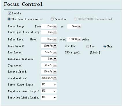
Focus adjustment range: Set software limit and stroke of the focusing motion.
Focus location after reset: define the origin corresponding to focus scale.
Pulse equivalent: Set the distance of movement focus corresponding to the number of pulses per revolution of the drive.
Return ORG direction: upward homing is negative direction, downward homing is positive direction.
Return ORG sampled signal: choose limit switch or origin switch as sampled signal.
Coarse positioning speed: quickly find the speed of origin switch when homing.
Precise positioning speed: Slowly precise positioning speed after find the origin switch.
Rollback distance: Reverse motion distance after completing precisely positioning.
Jog speed: Speed of clicking motion focus.
Positioning speed: Empty traverse speed when focus moves.
3.13 Optical edge seeking
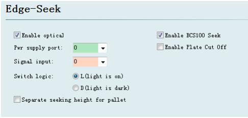
Optical edge seeking and capacitance edge seeking can be used after enter the set of edge seeking ,optical edge seeking must applies Omron E3Z-L61-type diffuse optical switch; capacitance edge seeking must applies BCS100 V3.0 height controller.
3.14 BCP5045
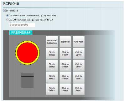
BCP5045 numerical control panel can be activated in numerical control panel interface. When used in a stand-alone environment, CypCut software will adaptively match the Mac address of BCP5045 numerical control panel, and automatically connect the control. When BCP5045 is used in LAN environment, please enter BCP5045 device ID number. BCP5045 is in total of 12 custom keys, which can be configured as a control button of double exchange workbench or other custom PLC.
Learn more about our products, please visit and subscribe to our Youtube channel
