Click the button to select the Part you want to view:
Part. 1
Part. 2
Part. 3
Part. 4
Part. 5
Part. 6
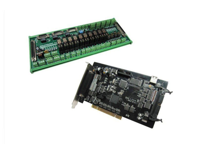
Part2: BCL3766 Wiring Instructions
The External IO Board of BCL3766 is installed by rail and also can be installed permanently. Its external size is 315mm*128mm with DM62M and DB37M interface in two sides, corresponding to JP1 and JP2 of BMC1604V2. C62-2 cable is used to connect External IO Board DB62 interface with JP1 port on the back of control card JP2 interface is linked by C37-40 baffle wire and then is fixed on erection fixture of computer with bolts. And C37-2 cable is used to connect DB37 socket on External IO Board.

The four DB15M interfaces on the top left corner are servo control signals, which are X axis, Y axis and W axis, respectively, from left to right. When being used as gantry dual drive, W axis is as Y2 axis. When being used as pipe cutting, W axis is as rotation axis.
High-low terminals on bottom left are respectively limit and origin signal of X axis and Y axis. High-low terminals on upper right are origin and limit input of W axis and general input interface, with all the low terminals break-over, as COM ground, namely 0V.
The interface on bottom right is 20 general outputs, thereto, 8 outputs as relay output, 12 outputs as mosfet output. The first 4 ones of the 8 relay outputs only have normally open contacts and the second 4 outputs have normally open contacts and the second 4 outputs have normally open contacts and normally closed contacts. The 8th mosfet output is 24 V general cathode output.
The three 2–pin terminals over right above are 1 PWM and 2 DA analog signal.
Dip switch:
There is a 4-bit dip switch below the PWM and DA analog signal. Its usage is shown as below :
The first bit (P1) and second bit (P2) of 4-bit dip switch choose PWM voltage.
[wptm id=31]
2.2 Signal type
2.2.1 Input signals
Input signals include: limit, origin and general input. The input of BMC1604 V2 card is active low level: support normally open and normally closed mode (The polarity of input port can be modified by “platform configuration tool” of CypCut software). When the setting is normally open, input port and 0 V break-over are active; when the setting is normally closed, disconnection of 0 V is active.
Input port polarity can be modified through the hardware jumper. Now IN13, IN14 and IN15 input ports support this function. Jumper has two states, ACT_LOW as shown in the figure, which means low level is active (inputting 0V voltage is active); ACT_HIGH as shown in the figure, which means high level is active (inputting 24V voltage is active). Default state is ACT_LOW.

Typical connection of optoelectronic switch is shown as below, which must use 24V switch of the NPN type (low level is active).

Typical connection of contact switch is shown as below:

Typical connection of magnetic switch is shown as below, which must use 24V switch of the NPN type.

2.2.2 Relay output signals
Load capacity of relay output contact on External IO Board is: 240VAC/5A, 30VDC/5A. Controllable small power is 220 V alternating load. Please connect contactor externally if connected with big power load.
The connection of relay output and contactor is shown as below:

2.2.3 Mosfet output signals
There are OUT9~OUT20, total 12 outputs, mosfet emitter output on BCL3762-V5.0 External IO Board and it can directly drive 24V direct current device.
Each current supply capacity is 500mA. Typical connection is shown as below:

2.2.4 Differential output signals
Pulse command state of control driver is “pulse+direction, negative logic”. The highest pulse frequency: 3MHZ. The pulse mode is shown as below:

The output way of differential signal is shown as below :

2.2.5 Analog output signals
There are 2 outputs of 0~10V analog signal in the External IO Board.
[wptm id=32]
2.2.6 PWM output signals
BCL3766 External IO Board has 1 PWM pulse width modulating signal which can be used for controlling average power of fiber laser. PWM signal level is 5 V or 24 V for selection. Duty cycle is 0%~100% and the highest carrier frequency is 50 KHz. The output way of PWM signal is shown as below:

We strongly recommend that users install PWM+/- signal to a relay output port in series (Set it to PWM+/- enable signal.), then access to the laser, which can avoid laser light leakage in modulation mode. Please refer to “2.5 Laser Connection” for more details. Furthermore, please adjust PWM signal level. 24 V or 5 V level can be selected through dip switch.
2.3 Terminal Instructions
2.3.1 External power source
External power source provide direct current 24 V for BCL3766 External IO Board. 24 V and COM of power input terminal are connected to 24 V and 0V of power output interface, respectively.
2.3.2 Servo control interface
The four servo control interfaces on BCL3766 are DB15 two-row bores, and pin definition is as below:

The signal definition of matched servo cables is shown as below:
[wptm id=33]
+24V,0V: Supply 24V DC power for servo drive; SON:
The output is servo enable signal when servo on; ALM:
Alarm, receive servo alarm signal;
PUL+, PUL-: Pulse (PULS), differential output signal;
DIR+,DIR-: Direction (DIR), differential output signal;
A+, A-, B+, B-, Z+, Z-: Three phase of encoder, input signal;
The polarity of SON and ALM signal can be modified through hardware jumper.

When the SON signal jump to ACT_LOW state, low level is active (inputting 0V voltage is active); When the SON signal jump to ACT_HIGH state, high level is active (inputting 24V voltage is active). Default state is ACT_LOW.
When the ALM signal jump to ACT_LOW state, low level is active (inputting 0V voltage is active); When the ALM signal jump to ACT_HIGH state, high level is active (inputting 24V voltage is active). Default state is ACT_LOW.
Please refer to “1.3.3 The wiring diagram of servo drive control signal” for connection of Panasonic, Yaskawa, Mitsubishi and Delta servo drivers.
Please pay attention to the following information when connect servo driver of other brands:
- Please confirm the type of servo driver SON signal you select whether low level is active or not. (That is, It is ON when connecting with 24V GND.)
- Confirm the parameters of servo driver are set as: the type of received pulse signal is “pulse + direction”
- Confirm whether t h e servo driver input terminal has external crash stopping signal input or not, and which logic the signal is.
- Before the trial operation of servo driver, 24 V power must be provided for External IO Board, for 24 V power servo driver needs is provided by External IO Board.
- If driver still cannot run, confirm that driver parameter is set as not using “positive & negative input inhibit”.
- Connect shielding layer of signal line with servo driver case.
2.3.3 The wiring diagram of servo drive control signal
FSCUT2000 Fiber Laser Cutting Control System motion control system apply the signal of “Pulse+Direction” to control servo driver. The pulse sending frequency cap is increased from the previous 750Kpps to 3Mpps.
Recommend using high-speed differential pulse signal, and setting the pulse equivalent of servo driver in 1000 ~2000, in order to improve the interpolation accuracy.

[wptm id=34]

[wptm id=35]

[wptm id=36]


[wptm id=37]
[wptm id=38]


The maximum pulse frequency of Mitsubishi J3 series is 1Mpps.
[wptm id=39]
Note:
Parameter settings above can guarantee basic sports only under the circumstances of the right wiring connection, not ensure control precision. And if you need to further optimize campaign results, please adjust the rigidity, gain, inertia ratio and other parameters.
Basic setting parameters of Mi Mitsubishi MR-J3 – A series
2.3.4 Origin and limit input X-:
The limit of minus X direction, dedicated input signal and low level is active;
X0: the origin signal, dedicated input signal and low level is active;
X+: the limit of positive X direction, dedicated input signal and low level is active;
COM: GND, the general interface of the above three signals;
Y-: the limit of minus Y direction, dedicated input signal and low level is active;
Y0: the origin signal, dedicated input signal and low level is active;
Y+: the limit of positive Y direction, dedicated input signal and low level is active;
COM: GND, the general interface of the above three signals;
W-: the limit of minus W direction, dedicated input signal and low level is active; W0: the origin signal, dedicated input signal and low level is active;
W+: the limit of positive W direction, dedicated input signal and low level is active;
COM: GND, the general interface of the above three signals;
The input logic of limit and origin signal can be modified through “platform configuration tool” coming with the CypCut software. Please refer to chapter 3 platform configuration tool for more details.
2.3.5 General input
There are 15 general inputs with IN1~IN15. 15 general inputs can be configured as various custom buttons or alarm input through “platform configuration tool” coming with the CypCut software. Please refer to chapter 3 platform configuration tool for more details.
2.3.6 General output
There are 8 relay outputs with OUT1~OUT8. 8 relay outputs can be configured as the control port corresponding to “laser”, “auxiliary gas”, “height controller”, “indicator light” through “platform configuration tool” coming with the CypCut software. Please refer to chapter 3 platform configuration tool for more details.
When BCL3766 External IO Board is selected, besides 8 relay outputs, there are also 12 mosfet outputs, which can directly drive 24V direct current device.
2.3.7 Analog output
DA1 and DA2 are 2 outputs of 0~10V analog signal. DA1 and DA2 can be configured as a control signal of controlling the laser peak power and proportional valve through “platform configuration tool” coming with the CypCut software.
2.3.8 PWM output
When the laser type is configured as “fiber laser” through “platform configuration tool” coming with the software, PWM output port will be activated and used for controlling fiber laser average power.
When PWM is controlled needing to use 5V, 1 pin of four bit dip switch is OFF, and 2 pin of four-bit dip switch is ON; Optionally select one among 3 pin and 4 pin is ON, then another one is OFF.
When PWM is controlled needing to use 24V, 1 pin of four bit dip switch is ON, and 2 pin of four bit dip switch is OFF; Optionally select one among 3 pin and 4 pin is ON, then another one is OFF.
2.4 Connection Diagram

2.5 Laser connection
2.5.1 YAG laser connection
Directly connect output port whose configuration is laser output signal to laser, which will not be covered here.
2.5.2 CO2 laser connection
Herein, Nanjing KRRASS RAS-2000SM CO2 FAF laser is included as an example, and lasers of other brands are similar.

Note:
Part of the CO2 laser also supports PWM control mode, and specific wiring connection can refer to MAX laser wiring diagram.
2.5.3 IPG-YLR series wiring diagram
When the laser you are using supports serial or Ethernet communications control, we strongly recommend that you connect communication ports (serial or network interface).
Using serial or Ethernet communication, CypCut software will monitor laser status in real-time, and can operate lasers by means of communication. Implementation including switch shutter (Emission), switch red (Guide beam), set the peak power (Current) and other actions, no longer need to connect the analog interface to control the laser peak power.
Recommended network interface of IPG-YLR series.
Note:
- Remote start button cannot be connected, especially when the laser is not in a good grounding , we do not recommend users to add remote start button, which is easy to cause the laser to produce failure.
- PWM select 24V control (Dip switch: 1 pin is ON, 2 pin is OFF;Optionally select one among 3 pin and 4 pin is ON, then another one is OFF.
2.5.4 Germany version IPG_YLS series wiring diagram

Note:
- B2 pin of XP1 interface cannot connect Emission ON, then make sure that the Emission Status input port is set as 0 in “platform configuration tool”, which means do not detect whether the shutter has been open or not.
- PWM select 24V control (Dip switch: 1 pin is ON, 2 pin is OFF;Optionally select one among 3 pin and 4 pin is ON, then another one is OFF.
2.5.5 America version IPG_YLS series wiring diagram
Note:
- B2 pin of XP1 interface cannot connect Emission ON, then make sure that the Emission Status input port is set as 0 in “platform configuration tool”, which means do not detect whether the shutter has been open or not.
- PWM select 24V control (Dip switch: 1 pin is ON, 2 pin is OFF);
2.5.6 SPI-500W-R4 wiring diagram

Note:
- When the modulation signal select MODINPUTTTL interface, PWM select 5V control (Dip switch: 1 pin is OFF, 2 pin is ON;Optionally select one among 3 pin and 4 pin is ON, then another one is OFF.
- When the modulation signal select 1 pin of I / O interface, PWM select 24V control (Dip switch: 1 pin is ON, 2 pin is OFF;Optionally select one among 3 pin and 4 pin is ON, then another one is OFF).
2.5.7 Bowflex MARS Series wiring diagram
Note:
PWM of Bowflex laser select 24V control (Dip switch: 1 pin is ON, 2 pin is OFF);
2.5.8 JK/GSI-FL Series wiring diagram

Note:
- Several wires on SK11 which need to be interlocked, can connect the appropriate equipment to ensure safety interlock in accordance with the corresponding interpretation.
- When the modulation signal select SK101 interface, PWM select 5V control (Dip switch: 1 pin is OFF, 2 pin is ON;Optionally select one among 3 pin and 4 pin is ON, then another one is OFF).
- When the modulation signal select 16 pin of PL5 interface, PWM select 24V control (Dip switch: 1 pin is ON, 2 pin is OFF;Optionally select one among 3 pin and 4 pin is ON, then another one is OFF.)
2.5.9 Rofin fiber laser wiring diagram

Note:
- Several wires on X720 which need to be interlocked, can connect the appropriate equipment to ensure safety interlock in accordance with the corresponding interpretation.
- PWM of Rofin laser select 5V control (Dip switch: 1 pin is OFF, 2 pin is ON;Optionally select one among 3 pin and 4 pin is ON, then another one is OFF.)
2.5.10 Raycus fiber laser wiring diagram

Note:
- Raycus new lasers need to use 24VPWM signal control, while the old ones use 5V PWM signal. And new lasers can use the serial port control only before the key switch is in the REM state, while key switch of the old ones is in the ON state. It will indicate whether the laser is 24V PWM interface control or not; when it’s not indicated or marked with 5V, 5V control mode can be applied totally.
- PWM select 5V control (Dip switch: 1 pin is OFF, 2 pin is ON;Optionally select one among 3 pin and 4 pin is ON, then another one is OFF.)
- PWM of Max laser select 24V control (Dip switch: 1 pin is ON, 2 pin is OFF; Optionally select one among 3 pin and 4 pin is ON, then another one is OFF.)
2.5.11 Max laser wiring diagram

Note:
- PD+PD- is a laser alarm output, connected to the input of BCL3766 External IO Board any interface, and with setting a custom laser warning (normally open) in “Platform Configuration – Alarm – Custom Alarm”.
- Red and Laser On enable GND can be incorporated together into any COM port of BCL3766.
- PWM of Max laser select 24V control (Dip switch: 1 pin is ON, 2 pin is OFF;Optionally select one among 3 pin and 4 pin is ON, then another one is OFF.)
Learn more about our products, please visit and subscribe to our Youtube channel


