This fiber laser cutting machine FSCUT4000 manual gives a detailed introduction to the usage of FSCUT4000 controller, including technical features and installation instructions etc. For CypCut laser cutting software operation, please refer to the CypCut user manual. For other matters you can contact us directly. Operating personnel should read the manual in detail which will be helpful for a better use of the product. Due to the continuous updating of product functions, the products you receive may differ from the statement in this manual in some respects. We apologize for any inconvenience it may cause.
1. Product Description
1.1 Brief Introduction
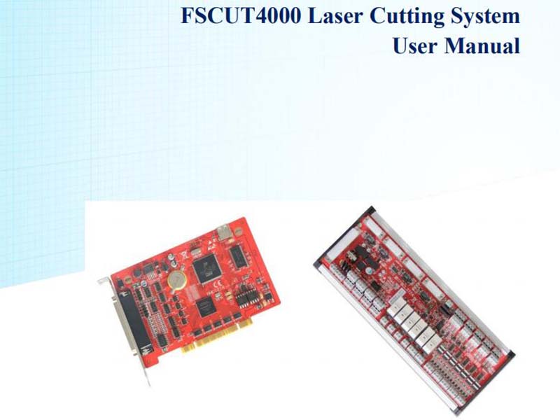
FSCUT4000 is a high performance laser cutting system of close-loop control developed by Shanghai Friendess Company. It is widely used in metal and non-metal laser cutting application, has gained wide popularity among users at home and abroad. This manual served as installation and operation guide for FSCUT4000 system. FSCUT4000 system hardware table:

1.2 Connection Diagram
BMC1214 card adopts PCI interface. Dimension: 155mm*106mm. The socket (DB62M) on control card connects with BCL3724 I/O terminal by C62-2 cable. Wiring diagram shown below:

1.3 Technical Reference

1.4 Control Card Installation
1.4.1 Install steps
- Power off computer, insert the control card into PCI socket, and fix the control card tightly;
- After start up computer, "Add Hardware Wizard" pops out and click "Cancel" button, as shown below. If this dialog box does not appear, indicating the card is in poor connection, please repeat the first step.

- Install CypCut software. The driver program will be installed by default option automatically.
- Open windows device manager to confirm installation succeed. Below image shows the installation is succeed.


1.4.2 Troubleshoot
- If "Find New Hardware" dialog box does not pop out after start up computer or control card does not shown in device manager, indicating that the control card is not in good connection with PCI socket. Please replace the PCI socket or change another computer, insert the control card tightly and reinstall software.
- If the device has a yellow exclamation mark, double-click to open its attributes page, and select "Detail Information" as shown below:


- If the first half of the ‘device instance ID’ attribute is displayed asit means computer has correctly recognized the motion control card but software installation might be failed. Try install CypCut again, if installation still fails, please contact our technical support.
- If the first half of ‘device instance ID’ attribute is not, it FSCUT4000 Laser Cutting Control System 10 indicates computer doesn't recognize the control card. Power off computer and change PCI socket, install the card firmly and repeat installation again.
- If step (4) still fails, the control card might be damaged please contact our technicians.

2. BCL3724 Wiring Instruction
2.1 BCL3724 Description
BCL3724 diagram shown as below:

You can either use guide rail or fixed installation to install BCL3724 board, product dimension 315mm*107mm. DB62M socket connected with JP1 interface of BMC1214 card by C62-2 cable.
4 sockets (DB15M) on top left are for servo control, from left to right is X, Y1, Y2 and W axis port.
The signal terminals on bottom left are positive/negative limit, origin inputs of X, Y and W axes. All lower terminals are conducted, ground end of COM, 0V.
On bottom right are 20 common output terminals which are thyristor emitter output. Thyristor output is 24V, common cathode.
Above are PWM signal and 4 DA analog signal terminals.
There is a DIP switch down below PWM: Switch P1 and P2 to set PWM voltage

2.2 Signal Type
2.2.1 Input signal
The input signals: positive/negative limit, origin, common input. All input terminals of BMC1214 are low-level active, support NO (normally-open) and NC (normally-close) input. When set input as normally-open, input signal active when conduct with 0V; when set input as normally-close, input signal active when disconnect with 0V.
The polarity of input can be changed by jump-wire, IN10, IN11, IN12 support jump-wire. There are 2 status of jump-wire, ACT_LOW means low-level active (input 0V active); ACT_HIGH means high-level active (input24V active). The default state is ACT_LOW.

The typical wiring of photo-electric switch shown below, must use NPN 24V type switch.

The typical wiring of contact switch shown below.

The typical wiring of magnetic switch shown below, must use NPN 24V type switch.

2.2.2 Relay output
There are 6 relay output on BCL3724 terminal board which are OUT1-OUT6. OUT1-OUT4 only support normally open, OUT5-OUT6 have both NO and NC options. The maximum load of relay: DC 30V, 8A; AC 250V, 8A. Recommend to use load under 2A, the inductive load or high power load will reduce the service time of relay switch. Wiring between relay output and contact shown below:

2.2.3 Thyristor output
There are 14 thyristor output on BCL3724 from OUT7-OUT20, which can drive 24V DC device directly, drive capacity is 500mA. Wiring diagram shown below:

2.2.4 Analog output
3 analog output of 0-10V.

2.2.5 PWM output
There is one PWM port on BCL3724 for laser average power modulation. There are 5V and 24V for options. The duty cycle is adjustable from 0%~100%, the highest carrier frequency 50 KHz. The signal output shown below:

Set PWM signal level, 5V or 24V set by DIP switch.
2.3 I/O Specification
2.3.1 External power supply
BCL3724 requires external 24V DC power supply. The 24V and COM connect with 24V and 0V of power supply.
2.3.2 Servo control port
The 4 servo ports on BCL3724 are DB15 sockets, signal pin description listed below:

The signal pin description of C15-1.5 cable listed below:

+24V, 0V: give 24V DC power supply to servo driver;
SON: servo-on output;
ALM: alarm input from servo;
DA, AGND: analog output for motor control;
CLR: alarm reset;
OS: zero speed clamp signal;
A+ 、 A- 、 B+ 、 B- 、 Z+ 、 Z-: Encoder 3-phase input signal, to check encoder zero point.
The polarity of SON and ALM can be changed by jump-wire;

SON signal jump wire to ACT_LOW, output is low-level active (output 0V active); Jump wire to ACT_HIGH, output is high-level active (output 24V active); Default is ACT_LOW.
ALM signal jump wire to ACT_LOW, input is low-level active (input 0V active); Jump wire to ACT_HIGH, input is high-level active (input 24V active); Default is ACT_LOW.
2.3.3 Servo drive control signal
The wiring diagram with Panasonic, Yaskawa, Sanyo and Schneider provided here.
For servo driver parameter setting you can take reference from ServoTools calculation.
If you have any question please contact our technical support.
For other brand servo wiring please take notice of following items:
- Make sure the servo supports velocity control mode. For example, Panasonic
A5 series servo must choose full-function type, cannot use pulse type; - Check if SON signal is low-level active (SON is active when conducted with
GND of 24V); - Check if there is external emergency stop in servo I/O;
- Before trial run of driver, provide 24V power supply to IO terminal board, the
24V power supply provided by BCL I/O board; - If driver still can't run, check if the parameter 'positive/negative direction drive
inhibit' in driver is disabled.


2.3.4 Origin and limit
X-: negative limit of X axis, dedicated input, low-level active;
XO: origin of X axis, dedicated input, low-level active;
X+: positive limit of X axis, dedicated input, low-level active;
COM: ground, the common end of above three signal ports.
Y1-: negative limit of Y1 axis, dedicated input, low-level active;
Y1O: origin of Y1 axis, dedicated input, low-level active;
Y1+: positive limit of Y1 axis, dedicated input, low-level active;
COM: ground, the common end of above three signal ports.
Y2-: negative limit of Y2 axis, dedicated input, low-level active;
Y2O: origin of Y2 axis, dedicated input, low-level active;
Y2+: positive limit of Y2 axis, dedicated input, low-level active;
COM: ground, the common end of above three signal ports.
W-: negative limit of W axis, dedicated input, low-level active;
WO: origin of W axis, dedicated input, low-level active;
W+: positive limit of W axis, dedicated input, low-level active;
COM: ground, the common end of above three signal ports.
You can change input polarity of origin and limit signals via machine config tool. See details in chapter 3 machine config.
2.3.5 Common input
There are 12 common input IN1-IN12. You can assign common inputs as userdefined software button or alarm input. See details in chapter 3 machine config.
2.3.6 Common output
There are 20 common output OUT1-OUT20. Common output can be assigned as user-defined signal output for laser, gas, indicator lamp controlling etc. See details in chapter 3 machine config.
2.3.7 Analog output
3 channels analog output of 0-10V, DA1, DA2 and DA3. Analog output can be assigned for laser peak power and gas valve control.
2.3.8 PWM output
For fiber laser configuration in CypCut machine config, PWM will be activated automatically for laser average power regulation. For other type laser, there is no signal output from PWM port.
2.4 Wiring Diagram

2.5 Laser Wiring Diagram
2.5.1 YAG laser
Assign an output for laser emission and connect with laser.
2.5.2 CO2 laser

Note: Some of CO2 laser also supports PWM control mode, wiring can take reference from Max laser.
2.5.3 IPG-YLR

It’s recommended to use serial communication (RS232) or network communication under serial or Ethernet communication, CypCut can monitor laser status in real time and control laser of emission, aiming, peak power without DA analog output.
Recommend to use network communication for IPG-YLR series.
Note:
- Remote start-up button is not necessary and not recommended for it might cause laser malfunction when laser is not well grounded.
- Select 24V for PWM (DIP switch: PIN1 ON, PIN2 OFF).
2.5.4 IPG_ YLS Germany

Note:
- B2 ‘Emission ON’ in XP1 interface is not necessary for CypCut, set ‘Emission
Status’ as ‘0’ in machine config, CypCut will not check laser emission status. - Select 24V for PWM (DIP switch: PIN1 ON, PIN2 OFF).
2.5.5 IPG_ YLS American

Note:
- B2 'Emission ON' in XP1 interface is not necessary for CypCut, set 'Emission
Status' as '0' in machine config, CypCut will not check laser emission status. - Select 24V for PWM (DIP switch: PIN1 ON, PIN2 OFF).
2.5.6 SPI-500W-R4

Note:
- When use MODINPUTTTL for laser modulation, select 5V for PWM (DIP switch: PIN1 OFF, PIN2 ON).
- When use PIN1 of I/O interface for laser modulation, select 24V for PWM (DIP switch: PIN1 ON, PIN2 OFF).
2.5.7 FEIBO MARS

2.5.8 JK/GSI-FL

Note:
- The interlock in SK11 interface
- When use SK101 as modulation, select 5V for PWM (DIP switch: PIN1 OFF,
PIN2 ON). - When use Pin-16 in PL5 as modulation, select 24V for PWM (DIP switch: PIN1
ON, PIN2 OFF).
2.5.9 Rofin

Note:
- Take related reference for wiring of interlock in X720;
- Select 5V for PWM ((DIP switch: PIN1 OFF, PIN2 ON; one of PIN3 or PIN4 ON and the other OFF).
2.5.10 Raycus
3. Machine Config Tool
3.1 Installation and Operation
CypCut default installation contains machine config program.
In Windows Start > All Programs > CypCut open machine config program .
'CypCut laser cutting system' is software name which might be different of OEM version.
3.2 Password
You have to input password to start config tool.

Initial password 61259023.
Note:
All settings in machine config must setup by actual mechanism structure. Wrong settings will cause severe unknown problem! In machine config, all input are yellow color, and all output are green color.
3.3 User Interface

The first page open machine config is machine config overview. Click tab in top and left bar will open each parameter setup page for different machine module. For example, above three are entrance for laser, height control and gas system setting page.
Click 'file location' will locate to folder of config data.
Click button in overview page will also open the parameter setting page of each module. Click 'Machine tool' will enter ' Machine' page.
Click 'import' to finish machine config setting by existing file. Click 'save' save the setting.
Note:
1. Data folder contains all config files of CypCut.
2. Data backup is in CypCut > File > Backup.
3.4 Mechanism Config

Config mechanism structure, single drive Y axis or dual-drive Y axis, also config rotary axis.
X axis range: the maximum travel range under software limit protection function, also the width of white frame in CypCut drawing board.
Y axis range: the maximum travel range under software limit protection function, also the length of white frame in CypCut drawing board.
Pulse equivalent: pulse output per 1mm linear distance on machine load. You can calculate by ServoTools.
Servo alarm: set the triggered polarity of alarm signal is normally open or close.
Max speed: maximum user speed and acceleration restricted by CypCut.
Pitch compensation: compensation method for mechanic error including backlash and offset error data from interferometer.
Squareness: this is to offset the error when X and Y mechanic is not orthogonal.
X/Y check: used for motor runaway risk checking.

Motor runaway check: to check if the motor rotation direction same with encoder feedback. For example: send voltage+ for motor rotation+. If encoder feedback pulses increase in positive value, it indicates motor rotation polarity same with encoder feedback. Otherwise, it cannot create a close loop control when motor rotation polarity different with encoder feedback, under this situation motor will never reach the target position and controller keep sending command signal, machine load will rush out, this scenario called ‘motor runaway’. (Note: if doesn’t pass motor runaway test, cannot open CypCut for machine spindle adjust).
The sequence of motor runaway check:
Close-loop jog: check the option and jog X axis, observe the motor rotation and encoder feedback polarity.
Open-loop jog: check the option controller only send analog output, doesn’t compare with feedback. Dual-drive axis doesn’t recommend this function.
Reverse X: if machine load direction not same with jog direction, click it to reverse it and doesn’t need to change setting in servo driver.
Pulse check: check if encoder feedback pulses match with controller command.
3.5 Return Origin Config
Enable soft limit: check this option, software limit function will force start all the time.
Prompt user at start: prompt message when open CypCut to inform user execute return origin operation.
Origin direction: select return origin direction needed. Return origin direction decides which coordinate quadrant system runs with. For example, return origin direction of X and Y are both in negative direction, system runs in first quadrant coordinate.
Origin signal: FSCUT4000 must use origin switch, cannot take limit as origin.
ORG measure: measure the installation distance between limit and origin switch.
Z-phase signal: whether or not capture Z-phase signal results different return
origin process. The return origin process of each mode will display in picture. Dualdrive gantry synchronize function only available when capture Z-phase signal return
origin.
Low speed: fine positioning speed, recommend to set 10mm/s.
High speed: course positioning speed, recommend to set 50mm/s.
Rollback: the distance motor rolls back after reach origin switch.
Limit logic: the polarity of limit and origin signal active.
3.6 Laser Configuration
CypCut programmed standard configuration for YAG, CO2, IPG, Raycus, SPI and many other brand laser, select laser type and there are different parameter settings under each page.
3.6.1 CO2 laser configuration

Mechanic shutter: the output for mechanic shutter.
Digital shutter: the output for digital shutter.
Response input: response input when open mechanic shutter.
Laser form: laser form can be set as continuous wave, gate pulse and high power pulse by mode 1 and mode 2 output.
DA port: there are three DA analog output, select one of them for laser power control.
DA range: set the analog voltage range.
Minimum power: the minimum laser power.
3.6.2 IPG laser configuration

PWM enable: select a relay output in BCL3724 board as switch of PWM signal.
Relay output can avoid laser leakage.
DA output: there are 3 DA ports of analog output, select one of them for laser power control. When use RS232 or network control doesn't require DA port.
IPG Fiber Laser Configuration:
Remote start button:
When key switch turns to remote control mode, you can startup laser by remote 45 FSCUT4000 Laser Cutting Control System button. If use remote start button, you need to setup the output port for the button.
(Remote start up button is not recommended, for it's easy to cause laser malfunction).
IPG remote control:
When use IPG remote control, CypCut will monitor laser status in real time, then communicate and control laser emission, guide beam and peak current etc. When use remote control mode, doesn't require DA analog port.
IPG remote control supports serial and network communication, user can set IP or COM port as needed. When laser and BCS100 both select network communication with PC, take notice that the network segment of each IP cannot be same. For example, IP segment of BCS100 is 10.1.1.x while laser IP set 192.168.1.x. Recommend to use network communication which is more stable. If use serial communication, the shielding layer and outer shell of the connected device must be well grounded.
3.6.3 Feibo/Rofin/SPI/GSI/JK laser configuration

Feibo, Raycus and SPI laser are similar with IPG laser configuration, and support serial communication.
Debug mode: when enable this mode, CypCut log window will display the communication code with laser.
3.6.4 Configuration of other laser type

Shutter enable: output to open laser shutter.
3.7 BCS100 Configuration
3.7.1 Use BCS100 as height control unit

Use BCS100 as height control unit, set IP address in machine config same in BCS100.
Details of setting IP address please check in BCS100 user manual P2.5.6.
3.7.2 Use external device as height control unit

CypCut supports I/O control mode for height controller of other brand. User can assign output with basic functions of lift, hold, up and down etc.
Start follow: output to start follow.
Lift/stop follow: output of stop follow and lift up.
Stop/hold: output of stop follow and hold still.
Jog up: output of jog Z axis up.
Jog down: output of jog Z axis down.
Follow in place: input signal of follow reached position.
Active level (follow in place input): active level of follow in place signal.
Note: If the port number set ‘0’, means this port not in use. If this port not assigned to any signal, doesn’t set any port number, otherwise it might cause error.
3.8 Gas System

Valve (H/L): master valve of high pressure or low pressure gas channel.
Air: set output for air switch.
Oxygen: set output for oxygen switch.
Nitrogen: set output for nitrogen switch.
Gas alarm: to set alarm check for each gas channel or master valve.
There are 3 DA ports of analog signal can be assigned for gas pressure regulation.
3.9 Alarm Configuration

3.9.1 Warning message
Display the warning message of yellow color when machine is running. You can edit the warning message.
3.9.2 Emergency stop button
When this signal port active will trigger emergency stop alarm.
3.9.3 Safety mode
Safety mode used for machine maintenance mode, under which machine speed and laser power will all be restricted to preset safety range.
3.9.4 Custom alarm
User can assign any input port as alarm, edit alarm description and active level of signal port, and select allowed machine actions in alarm status.
3.9.5 Allowed dual-drive error
Maximum dual-drive position error allowed, the threshold to trigger alarm.
3.10 Common input
Click function button and select controlled function and active level of input signal.
3.11 Common output

3.11.1 Output configuration
Aiming: output to control guide laser.
Lasering: system will send an output signal for indicator lamp when laser in emission.
Working: system will send an output signal for indicator lamp when laser in production.
Alarm lamp: system will send an output signal for alarm lamp when alarm triggered.
Alarm bell: system will send an output signal for alarm bell when alarm triggered.
Ready: after machine axes returned origin, system will send an output.
3.11.2 Auto lubricate
After this I/O is assigned for auto lubrication, CypCut will start time/running length counting and turn on/off lubrication when reach preset time/mileage interval.
3.11.3 Custom output
Assigned I/O will display software button under CypCut CNC tab. Custom I/O can select contact or self-lock control method.
3.11.4 Regional output
Regional output used for automatic dust extracting. When machine in production, laser head works in region A, output in region A will active and turn on dust extractor.
When laser head works from region A to region B, output 12 turns off and output 15 turns on.
Turn-off delay: when laser head works from one region to another one, output of last region will turn off after preset delay.
3.12 Find Edge Setting

CypCut supports find workpiece edge by capacitance sensing and photo-electric senor. Photo-electric sensor must be Omron E3Z-L61 model. Capacitance sensing realized by BCS100 height controller.
3.13 BCP5045 Panel

Enable BCP5045 panel in this page. In stand-alone environment, CypCut will connect to BCO5405 Mac address. In LAN environment, input ID of BCP5045. There are 12 custom buttons which can be assigned for machine function like PLC control or pallet control.
4. Electrical System Adjustment
4.1 Power Supply Checking
Connect BCL3724 I/O terminal board and BMC1214 control card by C62-pin cable, give 24V power supply to BCL3724 board. Make sure power supply in right wiring and no short circuit before power up.
Note: Do not hot plug BMC1214 card and C62-pin cable!
4.2 Basic Machine Motion Config Checking
Motor runaway risk exists in close-loop control, you need to do some checking points before first-time running. First, confirm some basic settings in 'machine config tool' in below image: motor type, servo alarm signal polarity, pulse equivalent, encoder feedback, input gain of speed command, for dual-Y drive structure you also need to confirm rotation direction of master motor and slave motor in case of mechanic twisting (Take notice that servo drive parameters should be same settings for dual-Y axes).
4.3 Hardware Signal Checking
Startup computer and open CypCut software. Open File tab > Diagnosis > IO Monitor.

Check each signal one by one: positive limit/negative limit/origin switch of each motor axis, DA signal, PWM signal, servo enable signal and all other input and output signal.
4.4 Basic Motion Test
First, set conservative PID value in servo driver. And set conservative value of motion control parameter in CypCut. In CypCut 'Layer' > 'Global Parameter' shown as below:

Test single motor axis make sure pulse equivalent set right.
After all limit and origin signal tested to work normally, execute each motor axis return origin to build mechanical coordinate.
4.5 CypCut Basic Function Test
On CypCut control panel(right side on screen), click direction button to jog control axes, lift up/down Z axis, turn on/off gas blow, open/close aiming laser, change laser burst power etc. to test each part function well. Confirm system can control laser, BCS100 height controller, gas and other devices function well.
4.6 Position-Loop PID Self Adjustment
In CNC tab > Auto adjust, to adjust position-loop PID parameter.

5. Adjustment Steps

6. Common Problems in Close-Loop control
6.1 Motor Runaway Error
Error source: system doesn't receive feedback pulse or receive abnormal pulses from encoder.
Checking points:
- Check the wiring, make sure servo enable signal, speed command signal and encoder signal are wired with correct signal pin;
- Check servo driver parameter: if set external enable, do not set deadband(neutral zone), and set zero offset value properly;
- Check PID parameters in velocity loop and current loop, servo rigid level cannot be too low.
6.2 Encoder and Speed Check Failed
Error source: in pulse check process, program detected received encoder pulses and maximum speed doesn't match with preset value.
Checking points:
- If test results remain same error value in repeated testing, check servo driver parameter if command speed gain and feedback pulses match the setting in CypCut machine config;
- If test results are different error value in repeated testing, encoder signal might be disturbed. Check in electrical cabinet if separate the wiring of strong current from weak current.
6.3 Position Error Too Large
Error source: the feedback position different with command position.
Checking points:
- Open CypCut machine config, and execute motor runaway check make sure the checking passed;
- If this error came after increasing acceleration in CypCut, might be caused by motor torque being restricted. Driver settings restrict motor torque or motor itself is of low torque type;
- If this error came after increasing speed in CypCut, motor speed might be limited. Servo parameter might limit motor speed, or exceed motor maximum speed;
- If this type error always exist when setting acceleration and speed from high to low level, it indicates servo system is of low rigid. Mechanic or driver inner loop is low rigid.
7. Optimize Machine Motion Performance
7.1 Calculate Inertia Ratio and Preview Machine Performance
Features
The inertia ratio is a crucial indicator of machine performance features. You can calculate inertia ratio of each motion axis of machine by ServoTools. Download link is http://downloads.fscut.com/. ServoTools interface shown below:
When inertia ratio is smaller than 200% machine runs in light load can reach high speed cutting.
When the inertia ratio is between 200% to 300% machine runs in medium load, cutting precision is declined compared with light load in high speed, cutting speed and low-pass frequency should be lower.

Setup low pass filter frequency as high as possible as long as not reducing marking contour precision. The standard of contour precision should be no waving at corner position in cutting star, rectangular or polygon etc. You can setup by experiential value in below table. Setup the cutting acceleration then adjust LPF 2 levels around. The cutting acceleration has to match with LPF, you cannot setup one of them too larger than the other one.

7.2 Curve precision and corner precision
It's recommended to use the default value. If it's really needed, you can fine tune the value a little bit around the default value.
If curve cutting precision doesn't reach requirement, you can lower the value, meanwhile cutting speed at curve also be reduced. Speed reduction is more obvious
under smaller precision value. If corner cutting precision is not satisfied, you can lower the value, meanwhile cutting speed at corner also be reduced. Sharpe corner will turn to round corner under a large precision value.
Learn more about our products, please visit and subscribe to our Youtube channel


hi, how to wirring ACT_high input, to make it effect, i wana use act high input for emergecy stop