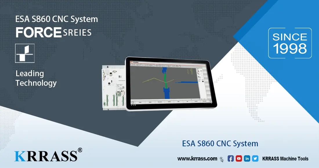
With the continuous expansion of the press brake market, the ESA system from Italy has gradually entered your field of vision. Today, I will introduce the tutorial on using the CNC electro-hydraulic press brake equipped with the ESA S860/S875 control system. I hope to help everyone.
Part 1: Fueling and Wiring
- Add anti-wear hydraulic oil to the fuel tank;

Add anti-wear hydraulic oil to the fuel tank - Connect to the power supply before first use;
Connect to the power supply before first use - Turn on the main gate of the power supply;
Turn on the main gate of the power supply - Turn on the power switch of the machine;
Turn on the power switch of the machine - Turn on the power switch, loosen the emergency stop, and start the oil pump;
Turn on the power switch Loosen the emergency stop Start the oil pump


Part 2: Daily boot steps
- Turn on the power switch of the machine;
Turn on the power switch of the machine - Turn on the power switch, loosen the emergency stop, and start the oil pump;
Turn on the power switch Loosen the emergency stop Start the oil pump - Wait for the ESA S860 system to start fully;
- Wait for the EsaBend software to start;

Wait for the EsaBend software to start - Click the "Edit" button;
- Under the "Manual Mode" page, find the reference point;
Under the “Manual Mode” page, find the reference point End For Find Reference Points - Test the operation of the X-axis;
Test the operation of the X-axis - Test the operation of the R axis;
Test the operation of the R axis - Test the operation of the Z1 axis;
Test the operation of the Z1 axis - Test the operation of the Z2 axis;
Test the operation of the Z2 axis - Test the operation of the A1 axis (i.e., the V axis);
Test the operation of the A1 axis - Under the "Die List" page, check the die parameters;
Under the Die List page, check the Die parameters - The die data corresponds to the actual;
Die data corresponds to the actual - upper die (Height 120mm) Die data corresponds to the actual - lower die (Width 18mm)
- Under the "Manual Mode" page, find the reference point;


Part 3: Programming numerical control
- Under the "Program List" page, add a new numerical program;
Under the Program List page, add a new numerical program - Input sheet width;
Input sheet width - Input sheet thickness;
Input sheet thickness - Select material;
Select material - Select upper and lower dies;
Select upper die Select lower die
- Input sheet width;
- Enter the step length and bending angle;
Enter the bending angle Enter the step length - Add the second work step;
Add the second work step - Enter the step length and bending angle again;
Enter the bending angle again Enter the step length again - Enter "Program Name" and save;
Enter Program Name and save - Enter the "Auto Mode" page and start bending;
Enter the Auto Mode page and start bending


Part 4: Bending Workpiece
- Put the board, the board is close to the block finger;
Put the board, the board is close to the block finger - Press the pedal;
Press the pedal - Complete the first work step;
Complete the first work step - Press the pedal;
Press the pedal - Complete the second work step;
Complete the second work step


Part 5: Measurement and Calibration
- Measure the length of the first step;
Measure the length of the first step - Measure the length of the second step;
- Use an angle ruler to measure the bending angle in two positions, left and right;
Use an angle ruler to measure the bending angle in two positions, left Use an angle ruler to measure the bending angle in two positions, right


Treatment method when the value is found to have an error:
- Enter the correction parameters for the corresponding axis;
Enter the correction parameters for the Y axis Enter the correction parameters for the X axis - Put the board again;
Put the board again - Measure again;
Measure again - The detection angle value is correct, and the calibration is completed.
The detection angle value is correct, left The detection angle value is correct, right


Part 6: Graphics Programming and 3D Simulation Bending
Graphics programming
- Under the "Program List" page, add a new graphic program;
Under the Program List page, add a new graphic program - Input sheet width;
Input sheet width - Input sheet thickness;
Input sheet thickness - Select material;
Select material - Select upper and lower dies;
Select upper die Select lower die - After confirmation, enter the "Edit" page;
After clicking OK to confirm, enter the editing page
- Input sheet width;
- Use graphics to generate the final bending program;
Use graphics to generate the final bending program - Under the "Edit" page, click "Calculate";
Under the Editing page, click Calculate button - Select the "Optimize" button;
Select the Optimize button - Select the "Simulation" button and keep clicking the "Continue" button until the workpiece is completed;
Select the Simulation button, and keep clicking the Continue button until the workpiece is completed The workpiece is completed


3D simulation bending
- Under the "Automatic Mode" page, click the icon in the lower right corner;
Under the Automatic Mode page, click the icon in the lower right corner - Select "Extrusion Viewer";
Select Extrusion Viewer - Select "First Bend";
Select First Bend - Click the "Start" button;
Click the Start button


Part 7: Shut down
- Press the pedal switch to make the upper mold dock the lower mold;
Press the pedal switch to make the upper mold dock the lower mold - Press the emergency stop button;
Press the emergency stop button - Close the EAS control software and save the data;
- Turn off the main power switch;
Press the emergency stop button Turn off the main power switch


Learn more about our products, please visit and subscribe to our Youtube channel


