The E300 controller is produced by Estun Company(Nanking China), it's widely used in NC press brake, high effective and easy operation. The following is the content of the operation manual of the E300 controller.
Preface
Purpose
This document provides guidelines for operating industries with the E300 controller. According to this document, you can learn how to use the E300 controller to program the product.
This document applies to:
- Technical Support Engineer
- Installation and commissioning engineer
- Operator
Organization This document consists of three chapters and is organized as follows.
| Chapter | Content | Detail |
|---|---|---|
| Chapter 1 | Outline | This chapter describes the features, appearance, and electrical specification of the E300 controller. |
| Chapter 2 | Programming | This chapter guides the user how to program the product by the E300 controller. |
| Chapter 3 | Basic Operation | This chapter describes the basic operation of the E300 controller. |
Conventions
Symbol Conventions
The symbols that may be found in this document are defined as follows.
 - Pictures 1")
General Conventions
| Convention | Description |
|---|---|
| Times New Roman | Normal paragraphs are in Times New Roman. |
| Boldface | Names of files, directories, folders, and users are in boldface. For example, log in as user root. |
| Courier New | Terminal display is in Courier New. |
| Italic | Book titles are in italics. |
GUI Conventions
| Format | Description |
|---|---|
| Boldface | Buttons, menus, parameters, tabs, windows, and dialog titles are in boldface. For example,click OK. |
| XX>XX | Multi-level menus are in boldface and separated by the “>” signs. For example, choose File>Create>Folder. Keyboard Operation |
Keyboard Operation
| Format | Description |
|---|---|
| Key | Press the key.For example, press Enter and press Tab. |
| Key 1+Key 2 | Press the keys concurrently. For example, pressing Ctrl+Alt+A means the three keys should be pressed concurrently. |
| Key 1, Key 2 | Press the keys in turn. For example, pressing Alt, A means the two keys should be pressed in turn. |
Chapter 1 - Outline
1.1 Introduction
The E300 controller is a dedicated NC (numerical control) device for the Torsion Bending Machine, which combines the expertise of ESTUN for many years and provides a complete economic solution for the Torsion Bending Machine with the support of unique drive control technology. The it adopts the integral product structure, built-in high-performance A8 processor, and configures 5.6 inch, 640 × 480 dot matrix, 18 full color display screen, and integrated IO ports, serial ports and USB port. The E300 controller is designed to be operated via the buttons on the front panel. At the same time, the pump switch and the emergency stop button are installed in the customized suspension cabinet to meet the user's requirements, as shown inFigure 1-1.
 - Pictures 2")
1.2 Features
The E300 controller inherits ESTUN classic mode of operation, through a simple and intuitive parameter configuration interface to complete the bending machine control operation. Its friendly interface, easy to use, practical function, and has the following features:
- 4 axes are supported, viz, X-axis, Y-axis, R-axis and C-axis.
- Automatic calculation of the block position, according to the bending angle, material, thickness and mold parameters.
- The back gauge can be controlled in a high-accuracysince the servo systems control X-axis and R-axis.
- Optional hydraulic or mechanical to control the C-axis.
- Program in absolute value or angle.
- You can backup, restore, import and export the parameters, for commissioning the machine easily.
- Edit the program in one page, for improving the operating efficiency.
- You can program the dwell time (holding time) andretracting delay by the device instead of the time relay.
- Interference or collision of the die can be avoided.
- The opening distance can be adjusted, for improving the operating efficiency.
- Automatically adjust the clamping point position.
- You can view the status of inputs, outputs, valves and faults on the Monitor page at any time.
- Automatically adjust the zero position of the R-axis.
- Materials and die informations are programable.
- Three of operation mode (Jog, Single, Continuous) for the jobs.
- Language setting and unit setting.
- IO ports can be allocated freely, and the device can detect them for avoid the repeat.
- Bilateral positioning and unilateral positioning.
- Slug clearance function.
- Teaching or search the reference point.
- The Axis, which is controlled by a servo system, can be manually moved.
- Real-time memory the parameters, positions and programs against the unexpectedaccidents such as interruption of power supply.
- Control Panel
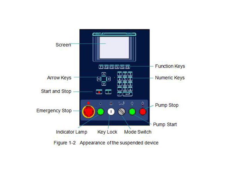
Figure 1-2is the appearance of the suspended device, and it includes many elements.
Table 1-1 Description of each element
| Element | Description |
|---|---|
| Screen | 5.6 inch, 640 × 480 dot matrix, 18-bit full color display screen. |
| Function Keys | Function keys, which corresponding to options on below of each page. |
| Numeric Keys | It consists of CLEAR, NUMBERS, POINT, ± and ENTER. They are often used in programming and settings. |
| Arrow Keys | Press these buttons can move the cursor. |
| Start and Stop | Press START key when your program has been completed, and each axis can performthe positioning. Press STOP key, the machine can stop running. |
| Mode Switch | Turn this switch for switching the operation mode between Single and Jog.: For switching the operation mode to Continuous mode, turn the switch to Single mode, and set the parameter Automatic to Enable on the HMI. |
| Emergency Stop | In the case of emergency stop use the EMERGENCY STOP controller. |
| Key Lock | A key lock, which can turn ON or turn OFF the device. |
| Indicator Lamp | When the device is power on, the indicator lamp can be lighted. |
| Pump Start | Press this button can turn on the oil pump, indicating the machine is ready. |
| Pump Stop | Press this button can turn off the oil pump, indicating the machine is unable to run. In addition, this signal can be cut off when EMERGENCY STOP button was pressed down. |
- Ports
There are 6 kinds of ports on the E300 controller which can connect the external devices. Table 1-2lists the description of them.
 - Pictures 3")
1.4 Electrical Specifications
| Item | Voltage | Rated Current | Starting Current | |
|---|---|---|---|---|
| Power Supply | Minimum | 20 | 1.2 | / |
| Standard | 24 | 2 | / | |
| Maximum | 28.8 | 3 | 3 | |
| Unit | V | A | A |
| Item | Description | |
|---|---|---|
| Inputs | Input Voltage | 24VDC±10% |
| Input Current | 5mA | |
| Signal Characteristic | H-level is not greater than 30VL-level is not greater than 1.2V | |
| Effective Level | H-level |
| Item | Description | |
|---|---|---|
| Outputs | Output structure | Open Collector |
| Output Voltage | Not greater than 30V DC | |
| Output Current | Not greater than 150mA | |
| Signal Characteristic | H-level is not greater than 30VL-level is not greater than 1.0V | |
| Effective Level | L-level |
| Item | Description | |
|---|---|---|
| Supported Type | Differential / Line Driver | Complementally / Voltage |
| Supply Voltage | 5V DC | 12V DC |
| Supply Current | 500mA | |
| Response Frequency | 500KHz | |
| Input Phases | A, B, C, A, B, C | |
| Output Phases | A, A, B, B, C, C | A, B, C |
| Output Voltage | H-level is not less than 80%VCCL-level is not greater than 0.3V | |
| Item | Description | |||
|---|---|---|---|---|
| Communication | Protocol | CAN | RS485 | RS232 |
| Transmission Rate | 1 Mbps | 10 Mbps | 115.2 Kbps | |
| Terminal Resistance | Build-in | None | ||
| ESD | 16KV HBM | 15KV HBM | ||
Chapter 2 - Programming
2.1 Page Structure
Power up the device and wait for a while, the screen can display the initial page (Single-Step) automatically, as shown in Figure 2-1.
 - Pictures 4")
- Title Bar
This area is displayed on every page, and from left to right are Page Name, System Status, and Operation Mode in turn.
- Page Name: displayed the current page’s name, e.g. SIngleStep, Multi, Program.
- System Status: displayed the current system status. There are six system statuses, as shown in Table 2-1.
Table 2-1 The description of the system status
| System Status | Description |
|---|---|
| Not Ready | When power up the device, the system detects the signalPump is turned OFF, this system status is displayed. |
| Idle |
|
| Run | |
| Alarm |
|
Operation Mode: displayed the current operation mode. There are three operation modes, as shown in Table 2-2.
 - Pictures 5")
- Parameters
This area displays the parameters information. Each page has corresponding parameters, for details about the parameters see the description of the other sections in this manual.
- Information
This area displays the information of each parameter, including editing value and range. The right side of this area is the system time.
- Navigation Bar
This area displayed each main page you may be switched, corresponding to the F1 to F6 keys on the operation panel.
Table 2-3lists the descriptions of each main page.
Table 2-3 The descriptions of each main page
| Key | Page | Description |
|---|---|---|
| F1 | Single | This page is used for setting the parameters of the single-step programming. Single-step programming is commonly employed for quick bending. |
| F2 | Multi | This page is used for setting the parameters of the Multi-step programming. Multi-step programming is commonly employed for the complex bending, which consist of many different bending steps. |
| F3 | Manual | The servo axes, which are controlled by servo motor, can be moved manually with the arrow keys in this page. You can perform this operation without starting the device. |
| F4 | Die | This page lists the information of the set and stored dies. |
| F5 | Programme | This page lists the information of the set and stored programs. |
| F6 | Constant | The commonly used parameters are displayed on Constant page. |
2.2 Operation Flow
 - Pictures 6")
2.4 Multi-Step
- Description
You can program the bending steps for the different settings on this page. Multi-step programming is commonly employed for the complex bending, which consist of many different bending steps.
Press F2 key to enter the Multi-Step page, as shown in Figure 2-4.
 - Pictures 7")
- Example
We take the following process as an example to describe the programming.
 - Pictures 8")
2.5 Manual Movement
 - Pictures 9")
- Press the arrow keys UP and DOWN to select the desired servo-axis.
- Press the arrow keys LEFT and RIGHT to select proper movement direction.
2.6 Die Settings
To program the process by the given angle, it is necessary to set parameters of the die.
Press F4 key to enter the Die page, as shown in Figure 2-6.
 - Pictures 10")
- Press arrow keys UP and DOWN to select the desired die ID.
- Press arrow keys LEFTand RIGHT to select the desired parameter of the die.
- Press NUMERICkeys to type the proper value.
The technical parameters diagram of the die are as shown in Figure 2-7.
 - Pictures 11")
- H: The height of the die, which is used in the bend depth calculation.
- V: The length of V-opening, which is the distance between the touching lines crossing.
- α : The angle of the die.
- R: The radius of the edges of the V-opening.
- S: Safety distance, which will be used in the case an R-axis,is mounted. This to prevent finger to die collision. The indicated minimum value iscomputed automatically from the die dimensions as follows:
S = FS+V/2, in which:
FS = flat section on the back side of the V-grove
V = opening value.
2.7 Bend Correction
It is necessary to commission the machine before your actual processing, in order to win an accurate bending result.
For performing it, you can program a bending process on Single-Step page, and operate the machine to complete one processing.
Then, measure the actual bending angle, bending depth, and the distance of the back gauge.
Check whether the bending result is corresponding with your requirement.
- Angle correction
The range of this parameter is from -90 to 90.
When the actual axis position is not corresponding with the displayed value, it is possible to correct the position with this parameter.
For example:
- When the programmed and displayed value is 90, while the actual axis positionvalue is 92, then you shall set the Corr. α to -2.
- When the programmed and displayed value is 90, while the actual axis positionvalue is 88, then you shall set the Corr. α to 2
- Y-axis correction
The range of this parameter is from ﹣99.999 to 99.999.
When the actual axis position is not corresponding with the displayed value, it is possible to correct the position with this parameter.
It may be repeating to set Corr. Y. However, we can learn from experience, program the process by the given angle, and measure the depth of 1 degree as the unit length. Then, program the process by the given depth, and set Corr. Y according to the unit length. Repeat this operation, until the bending result is corresponding with your requirement.
- X-axis correction
The range of this parameter is from ﹣99.999 to 99.999.
When the actual axis position is not corresponding with the displayed value, it is possible to correct the position with this parameter.
The setting of X-axis correction is same with Angle correction. For example:
- When the programmed and displayed value is 100.00, while the actual axis position value is 102.05, then you shall set the Corr. X to -2.05.
- When the programmed and displayed value is 100.00, while the actual axis position value is 98.05, then you shall set the Corr. X to 1.95.
2.8 Program Management
2.8.1 Create a Program
Press F5 key to enter the Program page, as shown in Figure 2-8.
 - Pictures 12")
Move the cursor on the program Name, and press NUMBERS keys to type a desired name. The typing method is 10 keys, that is, the numbers and letters on the same key can be switched by pressing severaltimes. For example, 2, C and D are in the same key, press once, shown as 2; quickly press twice, shown as C; quickly press three times, shown as D. Press ENTER key to confirm your typing, the software can generate the Steps, Die and Date.
2.8.2 Edit the Program
Move the cursor on the program ID you want to edit, and press ENTER key to enter the Multi-Step page. In addition, when you enter the Multi-Step page, the selected program has been loaded.
For details about the program see the section 2.4 Multi-Step.
2.8.3 Delete a Program
Move the cursor on the program ID you want to delete, and press CLEAR key. The page can display a dialog for asking whether to delete the selected item. Press OK to delete the selected program.
2.9 Teaching
In order to obtain the position values of the servo axes, the user needs to perform Teaching operation before the bending process, which can indicate the current position of the servo axis.
The diagram of machine coordinate system is as shown in Figure 2-9. You can refer to this diagram to complete the teaching value of the measurement and set.
 - Pictures 13")
Type the password 1212 in Constant page to enter TechIn Para page, as shown in Figure 2-10.
 - Pictures 14")
Press the arrow keys UP and DOWN to select a parameter, and type the desired value for them.
- Y Teaching and Clamping Point
The purpose of teaching Y-axis is obtaining the comparativeposition value of clamping point. When you teach Y-axis, it is necessary to estimate the position value of the Y-axis in advance. For example, if the position of the Y-axis is estimated to be 50mm, and the procedureis as follows:
Step 2 Select the parameter Y Teaching in TechIn Para page, and set it to 50.
Step 3 Return to the Single-Step page, and set the parameter Angle to 180, and the other parameters can be set arbitrarily.
In general, when the machine is in clamping, the punch just against the top of the sheet, so the bending Angle is set to 180, in order to ensure that the sheet was clamped.
Step 4 Run the device, and record the Y-axis position displayed on the device when the process is in Dwell.
Step 5 Enter the TechIn Parapage again, and fill the recorded value in the parameter Clamping Point.
- X Teaching
To teach the X-axis, you can measure the actual position of the X-axis, that is to say, measure the linear distance between the V-opening center of the die and back gauge.
Although there are many methods for teaching X-axis, their purpose is to ensure the processing accuracy. It is recommended that the user can run the machine once after roughly measuring the distance, that is, program a simple Single-Step program. For example, the measurement of the X-axis distance of 100mm, and the procedureis as follows:
Step 6 Select the parameter X Teaching in TechIn Parapage, and set it to 100.
Step 7 Return to the Single-Step page, and set the parameter X-axis to 100, and the other parameters can be set arbitrarily.
Here we need not to consider the error from the machine itself.
Step 8 Run the machine. When the bending step has been completed, measure and record the worked sheet.
Step 9 Enter the TechIn Para page again, and fill the recorded value in the parameter X Teaching.
- R Teaching
To teach the R-axis, you can measure and record the actual position of the R-axis directly, that is, measure the vertical distance between the top of the die and the back gauge. Then, enter the TechIn Para page again, and fill the recorded value in the parameter R Teaching.
Chapter 3 - Basic Operation
3.1 Start
- How to start
Press START key to startup the machine when you complete the program on Single-Step page or Multi-Step page, the servo-axis can start to positioning. When the machine is ready, it can be produced. However, it is unavailable to press START key on other pages.
- Start state
When the device is running, its indicator lamp can be lighting. In addition, you can see the status on the top of page is RUN.
3.2 Stop
- How to stop
There are 3 cases for stopping the device.
- Stop by a fault: If any fault occurred during the operation, the machine can stop automatically.
- Normally Stop: it also includes the following case:
- Manual stop: press STOP key, the running machine can stop.
- Count is finished: for the Count Mode is Cnt Down, when the Stock is 0, the running machine can stop automatically.
- Emergency Stop: press down EMERGENCY STOP button, the power supply of the system can be cut off.
- Stop state
When the device is stopped, its indicator lamp can be lighting. In addition, you can see the status on the top of page is Idle or Alarm.
3.3 Alarm and Reset
- Alarm information
As shown in Figure 3-1, which indicates a fault had occurred during the operation. It is necessary to solveit for recovering the running machine.
 - Pictures 15")
- How to reset
Follow the section Appendix D Alarm List, solving the fault according to the fault message, and then move the cursor on Clear, and press ENTER key, so that the system can try to reset.
However, the fault message may display again if the fault hasn’t been solved properly.
Move the cursor on Cancel and press ENTER key, the AlarmInfo dialog-box can be hiddentemporarily. To display it again, press CLEAR key when the page is on SingleStep or Multi-Step.
3.4 Monitor
You can view the ports allocation, valve status and fault list on Status Monitor page.
- Press and hold STARTkey for 3 seconds when the machine is running.
- Press and hold STOP key for 3 seconds when the machine is not running.
- Valve state
When you enter Status Monitor page, you can view the Valve Status tab, as shown in Figure 3-2.
 - Pictures 16")
On Valve Status tab, you can view the output status of valves. Blue background indicates the port is turned ON while Blank indicates the port is turned OFF.
You can view the current valve status on Curr.row, and the other rows shows the allocation in corresponding process.
For example, you have allocated the process Press as YV1 and YV3, when the machine is in Press process, the Curr.Row displays on YV1 and YV3.
- I/O state
Press arrow key RIGHT on the Valve Status tab, you can view the IO Status table, as shown in Figure 3-3.
 - Pictures 17")
Green background indicates the port is turned ON, while Blank indicates the port is turned OFF.
- Alarm history
Press arrow key RIGHT on the IO Status tab, you can view the Alarm Record table, as shown in Figure 3-4.
 - Pictures 18")
- ID: numbering for the alarm list, descending sort by Alarm Date, i.e. ID 1 is the latestfault message.
- Alarm Num: to show the code of the fault. For detail about solving the faults, see the section.Appendix D Alarm List.
- Alarm Reason: to show summary recordof the fault.
- Alarm Date: to show when this fault occurred.
3.5 Constant
The commonly used parameters are displayed on Constant page, as shown inFigure 3-5.
 - Pictures 19")
Table 3-1 The description of the parameters on Constant page
 - Pictures 20")
Appendix A Glossary
Appendix B Parameters Lists
- Constant
- Die
Appendix C Timing Charts
As shownFigure C-1andFigure C-2, you can view two timing charts, which are taken one ordinary bending step as the examples for representing the working status of each component.
 - Pictures 24")
 - Pictures 25")
 - Pictures 26")
Appendix D Alarm List
 - Pictures 27")
 - Pictures 28")
 - Pictures 29")
 - Pictures 30")
 - Pictures 31")
 - Pictures 32")
 - Pictures 33")
Learn more about our products, please visit and subscribe to our Youtube channel


