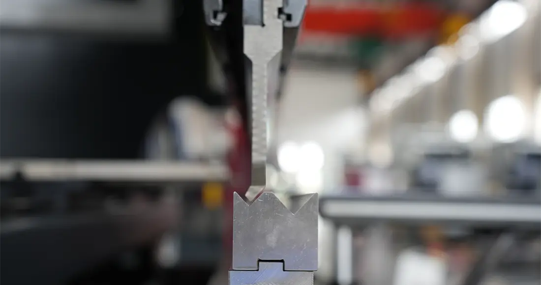
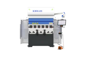
Press brake tools are the tools used in a press brake machine to bend sheet metal. They are made up of two parts: the punch and the die. The punch is the part that pushes the sheet metal, and the die is the part that receives the sheet metal and forms the bend. In the previous article, we explained to you the preparations before the start of the press brake, and in today’s article, we will explain to you how to add and set molds to the press brake. Adding and setting up tooling for your press brake requires specific steps to follow. The following are basic guidelines for doing this process in general:
1. Install the tools to the workbench
- Prepare the tools: Select the appropriate tools according to your needs. Make sure the size and shape of the tools matches the desired bending requirements.
- Clean the workbench: Make sure the workbench is clean and clear of any obstructions that may interfere with mold installation and operation.
- Mounting the tools: Mounting the tools to the punch or die base of the press brake, depending on the type and design of the press brake. Follow the instruction manual or operating guide for your press brake.
- Adjust the position of the tools: adjust the position of the tools according to the required bending angle and curve shape. Use adjustments on the press brake, such as bolts or manual levers, to ensure the die is in the correct position.
- Tightening the tools: Make sure the tools are securely fastened to the press brake to prevent them from moving or loosening during operation. Using an appropriate tool, such as a wrench or screwdriver, tighten the bolts or fixtures on the tools.
Please note that the above steps provide general guidance only, and the specific operation steps may vary depending on the type and model of the press brake. Before proceeding with tooling installation, please refer to the operating manual and guidelines for the specific press brake you are using to ensure proper operation and safe use.
2. Add tools and adjust parameters in the controller
The Delem controller is a control system commonly used on metal press brakes, which provides precise control and adjustment of the bending process. Here are the general steps to add tools and adjust parameters in the Delem DA-58T controller:
1. Log into the controller: Apply main power to the press brake, turn on the Delem DA-58T controller, and log into the system with the appropriate login credentials.
2. Navigate to the “Machine” management interface: On the main menu or navigation panel at the bottom of the controller, find the “Machine” management or related options, and select to enter this interface.

3. Add tools: In the “machine” management interface, you can see the labels “Punches” and “Bottom dies” for selection, select the corresponding upper and lower mold labels, click the “new” button and follow the prompts of the controller or Interface guide to operate adding new molds. Usually, you need to enter the parameters of the mold, such as length, width and bending radius, etc. (please refer to the following for details on adding molds).
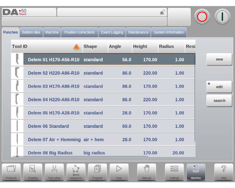
4. Save the tool: When you are done adding mold parameters, make sure to save your settings. Follow the save options or instructions on the controller interface.
5. Select a tool: Return to the main menu or operation interface, and find the “Tool Setup” option. In the “Tool Setup” option of the Delem controller, there are usually selection buttons for “Select Punch” and “Select die”. Select the stencil you added and make sure it is loaded correctly.
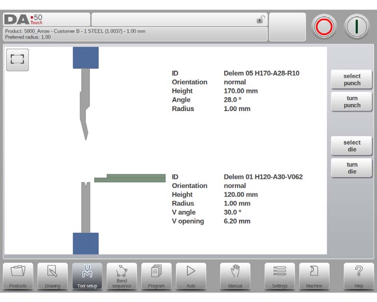
6. Adjustment parameters: Once the mold is selected, you can enter the adjustment interface of product editing. Through this option you can access various bend parameters such as bend force, angle control, springback compensation, etc.
7. Setting parameters: Adjust the parameters in the controller according to your needs and bending requirements. These parameters can be individually set for different mold and workpiece types. Use the buttons, sliders or digital inputs on the controller interface to adjust parameters one by one and fine-tune them according to your experience and requirements.
8. Save Parameters: When you are done adjusting parameters, make sure to save your settings. Follow the save options or instructions on the controller interface.
9. Make a bend: After completing the above steps, you can start to use the Delem controller to make bends. According to the set parameters, the controller will provide precise bending control and angle measurement.
Note that the steps above are general guidelines, and specific steps may vary by Delem controller tool and software version. Before making tool additions and parameter adjustments, please refer to the operation manual and user guide for the specific Delem controller you are using to ensure proper operation and safe use.
3. How to Program tools in the Delem DA58T Controller
3.1. Programming of Punches
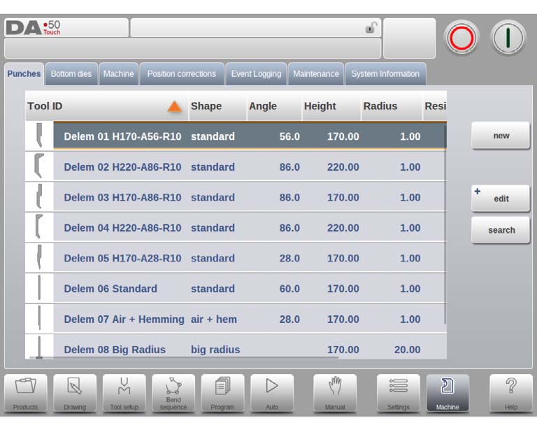
In this tab, the punches used in the machine can be programmed. New punches can be
added; existing punches can be edited, copied, renamed and deleted.
3.1.1. Create a new punch
To create a new punch, tap New in the library. The punch profile can be created with help of the programming and drawing facilities of the control.
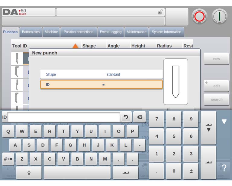
First the shape of the punch and its ID must be programmed. After that the shape details must be programmed following the wizard.
Shape
A selection must be done from the different available basic punch shapes corresponding to the required punch action. Options are:
- Standard Punch shape as normally used for air bending and basic bottoming.
- Hem Bend Punch as typical tool with flat bottom for specific hem bends.
- Air + Hem Bend Punch as tool for normal air bends and hem function.
- Big Radius Punch shape especially for big radius bends.
ID
A unique name or number to identify the tool. The maximum length is 25 characters.
The ID parameter may also contain alphanumeric characters. When finished, use Accept to leave this window and start with the tool data parameters. The control will prompt a window for the tool properties starting with the initial dimensions of the tool.
Depending on the chosen basic shape, the parameters will differ. In the following paragraphs the available punch shapes are described in detail.
3.1.2. Standard punch
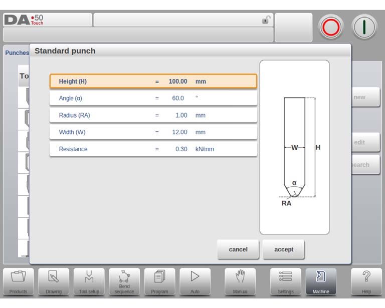
Height
The height the tool. Important: this height value will be used in the bend depth calculation.
Angle
The angle of the punch tip.
Radius
The radius of the punch tip. This value will be used as inner radius of the bend to make when this radius value is bigger than the inner radius as will result from the bending process.
Width
The width of the tool to program.
Resistance
Maximum allowable force on the tool.
Orientation of the punch on the screen
The right hand side of the tool is the back gauge side. The bottom point of the punch will be placed on the center line of the press brake shape.
Drawing
After entering these typical values you can create the tool drawing with the drawing facilities. Drawing a tool profile is done by entering angle values and line length values. Also the Touch drawing tools are available as with the product drawing method.
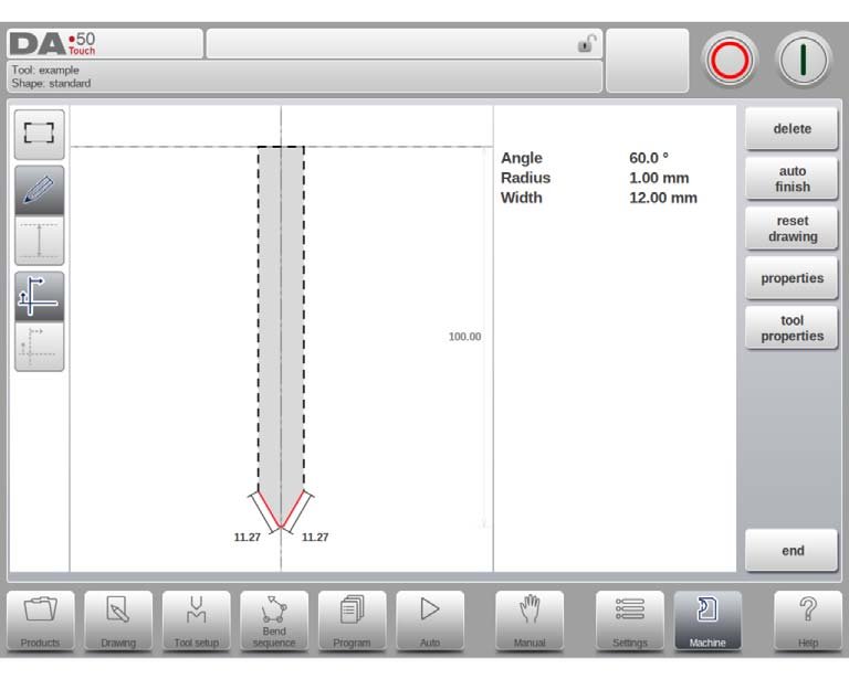
Following functions are available while drawing
Delete Line
To delete a line segment.
Auto Finish
Finishing the tool outline to the top of the tool automatically.
Reset Drawing
To reset the programmed drawing of the tool till the basic, initial shape, when creating a new punch.
Reload Drawing
To reload the programmed drawing of the tool till the basic, initial shape, when changing an existing punch.
Properties
To change the specific properties of the line or angle, add or remove a radius, change the length, etc. It is e.g. possible to add a radius in the outline of the tool.
Hemming can be part of the properties of lines. Within the shape of a tool a surface can be appointed as a hemming surface. This will enable the tool for hemming operation.
Tool Properties
To change the generic tool data and description.
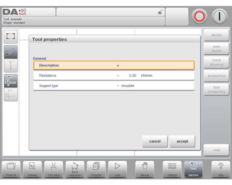
Description
A name or description of this tool. The maximum length is 25 characters. This description has already been entered in the beginning defining the tool, but can be edited in this field. The description is listed in the tool overview of the library.
Resistance
Maximum allowable force on the tool.
Support type
Switch parameter, to account for differently mounted punches. Such punches could cause inaccuracies in the tool height and the resulting Y-axis position. The control makes a distinction between two settings, 'head mounted' and 'shoulder mounted'.
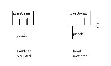
If 'shoulder mounted' is chosen, the Y-axis position is calculated from the standard tool height.
This is the default setting.
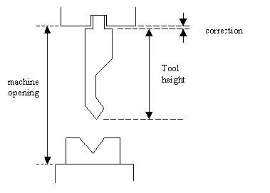
If 'head mounted' is chosen, a correction is made for Y-axis computation
Edit punch
To edit an existing tool, tap the tool in the library. The tool appears on the screen and can be edited with the drawing facilities.
3.1.3. Hem bend punch
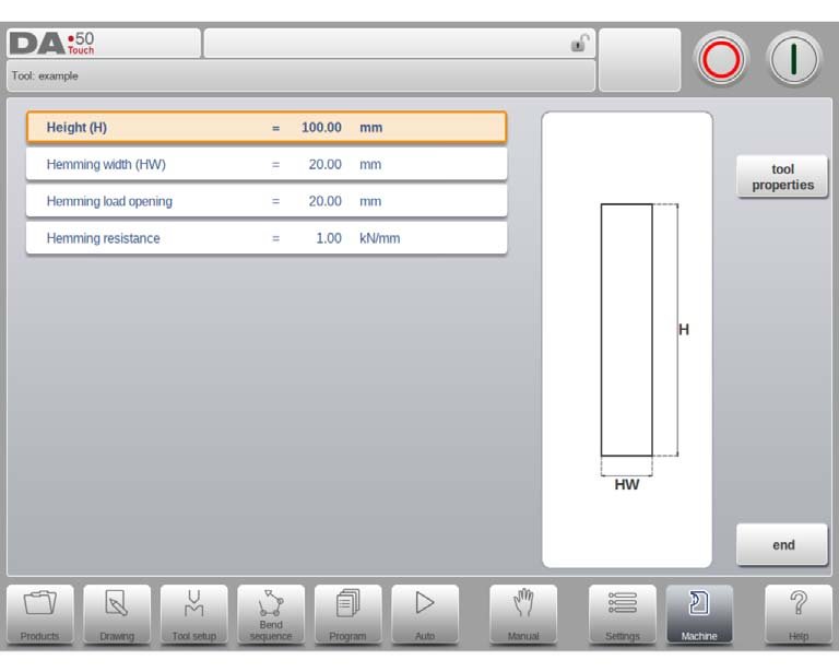
Height
The total height of the tool. Important: this height value will be used in the bend depth calculation.
Hemming width
The width of the tool to program.
Hemming load opening
Depending on the construction of your machine you can program here an opening position for your punch at which position you can put in your product to hem the particular bend. The opening position will also take twice the sheet thickness into account.
Hemming resistance
Maximum allowable force on the tool during hemming.
3.1.4. Air + hem bend punch
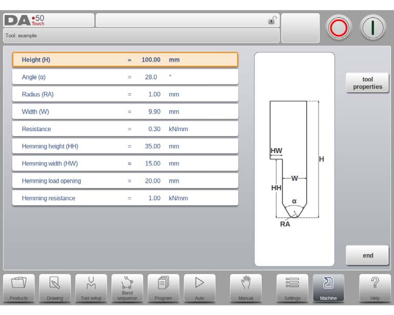
Height
The total height of the tool. Important: this height value will be used in the bend depth calculation.
Angle
The angle of the punch tip.
Radius
The radius of the punch tip. This value will be used as inner radius of the bend to make when this radius value is bigger than the inner radius as will result from the bending process.
Width
The width of the tool to program.
Resistance
Maximum allowable force on the tool.
Hemming height
The height of the punch used to move down in case of the hemming function.
Hemming width
The width of the punch part used to lay in the product for the hemming action.
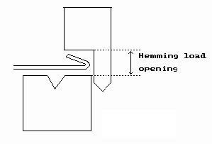
Hemming load opening
Depending on the construction of your machine you can program here an opening position for your punch at which position you can put in your product to hem the particular bend. The opening position will also take twice the sheet thickness into account.
Hemming resistance
Maximum allowable force on the tool during hemming.
3.1.5. Big radius punch
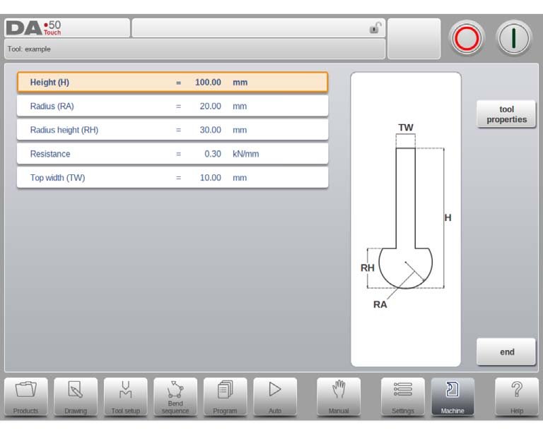
Height
The total height of the tool. Important: this height value will be used in the bend depth calculation.
Radius
The radius of the punch tip.
Radius height
The height of the big radius part of the tool.
Resistance
Maximum allowable force on the tool.
Top width
The width of the tool on the top side of the punch.
3.2. Programming of bottom dies
In this tab, the bottom dies used in the machine can be programmed. New dies can be added; existing dies can be edited, copied, renamed and deleted.
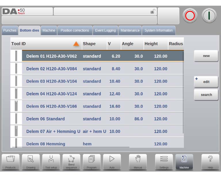
3.2.1. Create a new die
To create a new die, tap New in the library. The die profile can be created with help of the programming and drawing facilities of the control.
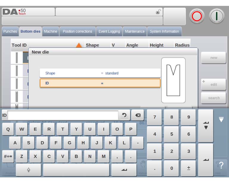
First the shape of the die and its ID must be programmed. After that the shape details must be programmed following the wizard.
Shape
A selection must be done from the different available basic die shapes corresponding to
the required die action. Options are:
- Standard Die shape as normally used for air bending and basic bottoming.
- Hem Bend Die as typical tool with flat top for specific hem bends.
- Inside Hem Bend Die as tool for air bends and hem function.
- Air + Hem Bend U Die shape for air bends and specific hem function.
ID
A unique name or number to identify the tool. The maximum length is 25 characters.
The ID parameter may also contain alphanumeric characters. When finished, use Accept to leave this window and start with the tool data parameters. The control will prompt a window for the tool properties starting with the initial dimensions of the tool.
Depending on the chosen basic shape, the parameters will differ. In the following paragraphs the available die shapes are described in detail.
3.2.2. Standard die
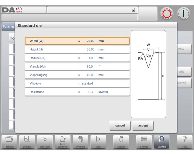
Width
The width of the tool to program.
Height
The total height of the tool. Important: this height value will be used in the bend depth calculation.
Radius
The radius of the edges of the V-opening.
V angle
The angle of the die.
V opening
The V-opening of the die.
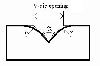
The V-opening is the distance between the touching lines crossing.
V bottom
Herewith the different possible bottoms inside the V opening can be defined:
- Standard is a sharp angle in the bottom of the die.
- Round is a die bottom with a radius to be programmed with the parameter 'Inside radius'.
- Flat is a flat die bottom with a certain dimension to be set with the parameter 'Bottom width'.
Resistance
Maximum allowable force on the tool.
Orientation of the die on the screen
The right hand side of the tool is the back gauge side. The mid-position of the V-opening will be placed on the centre line of the press brake shape.
Drawing
After entering these typical values you can create the tool drawing with the drawing facilities. Drawing a tool profile is done by entering angle values and line length values. Also the Touch drawing tools are available as with the product drawing method.
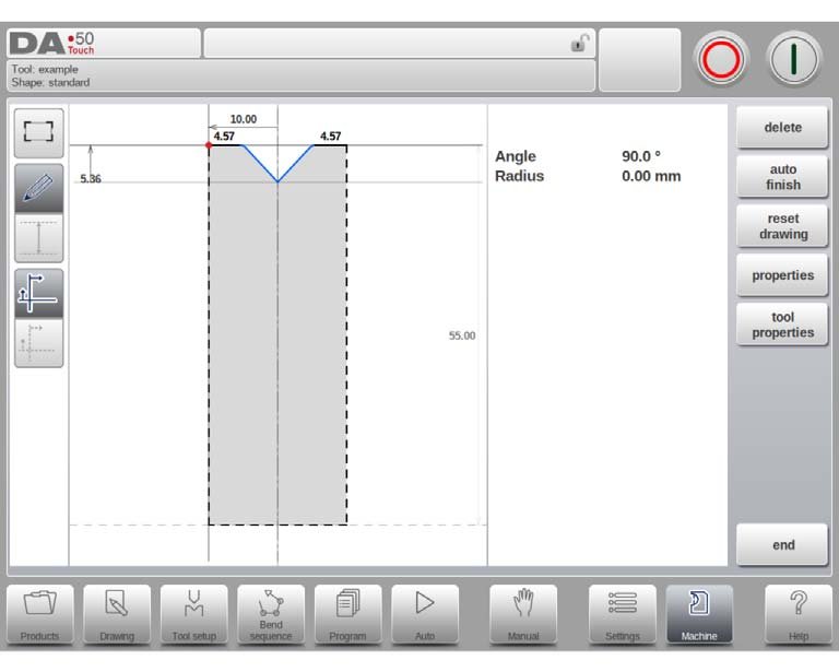
Following functions are available while drawing
Delete Line
To delete a line segment.
Change Height
To change the height dimension of the tool.
Auto Finish
Finishing the tool outline to the top of the tool automatically.
Reset Drawing
To reset the programmed drawing of the tool till the basic, initial shape, when creating a new die.
Reload Drawing
To reload the programmed drawing of the tool till the basic, initial shape, when changing an existing die.
Properties
To change the specific properties of the line or angle, add or remove a radius, change the length, etc. It is e.g. possible to add a radius in the outline of the tool.
Hemming can be part of the propertie of lines. Within the shape of a tool a surface can be appointed as a hemming surface. This will enable the tool for hemming operation.
Tool Properties
To change the generic tool data and description.
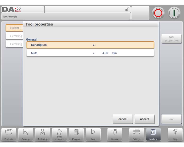
Description
A name or description of this tool. The maximum length is 25 characters. This description has already been entered in the beginning defining the tool, but can be edited in this field. The description is listed in the tool overview of the library.
Resistance
Maximum allowable force on the tool.
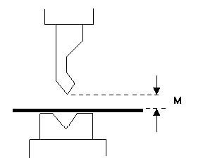
Mute
Muting distance. Distance above the sheet at which the speed change takes place.
Edit die
To edit an existing tool, tap the tool in the library. The tool appears on the screen and can be edited with the drawing facilities.
3.2.3. Hem bend die
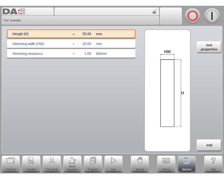
Height
The total height of the tool. Important: this height value will be used in the bend depth calculation.
Hemming width
The width of the tool to program.
Hemming resistance
Maximum allowable force on the tool during hemming.
3.2.4. Inside hem bend die
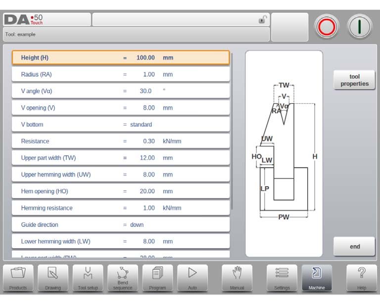
Height
The total height of the tool. Important: this height value will be used in the bend depth calculation.
Radius
The radius of the edges of the V-opening.
V angle
The angle of the die.
V opening
The V-opening of the die.
V bottom
Herewith the different possible bottoms inside the V opening can be defined:
- 'Standard' is a sharp angle in the bottom of the die.
- 'Round' is a die bottom with a radius to be programmed with the parameter 'Inside radius'.
- 'Flat' is a flat die bottom with a certain dimension to be set with the parameter 'Bottom width'.
Resistance
Maximum allowable force on the tool.
Upper part width
The width of the upper part of the die.
Upper hemming width
The width of the segment in the upper part of the die used for the hemming action.
Hem opening
The opening height of the die in the opened status to place the product with the hem bend.
Hemming resistance
Maximum allowable force on the tool during hemming.
Guide direction
Defines the mechanical construction of the inside hem die.
Lower hemming width
The width of the segment in the lower part of the die used for the hemming action.
Lower part width
The width of the lower part of the die.
Lower part height
The height of the lower part of the die.
Inside hemming die type
For the different types of available inside hemming dies the specific operation mode can be selected:
- Spring Opened: This die has an internal spring to push the die upwards as start position. Pre-Bend: For the pre-bend the sheet will be placed on top of the die in this opened position and the final bend position is calculated such that the required pre-bend angle will be reached. The backgauge height (R-axis) will be calculated on the level of the opened die so that the product can be placed against the backstop. Hem-Bend: For the hemming operation the pre-bent product will be placed in the hem opening of the die and the depth calculation of the pressing beam will be such that the die is pressed down until the hem bend is finished. The calculation will take twice the sheet thickness into account. It is possible to program an additional hem opening parameter in the specific bend parameters as offset on the final hem position.
- Open & Locked: This die is standard locked in a high position for normal bending and pre-bend angles. The lock mechanism must be removed to use the hemming facility.
- Normally Closed: This die is in a closed, low position for normal bending and pre-bend angles, and should be activated to get the hemming action.
Adapt decompression
To enable the addition of the hem opening value to the decompression distance.
no => not added at all.
yes => added for both air bends and hem bends.
air bend => added for air bends only (only available for spring opened hemming dies).
3.2.5. Air + hem bend U die
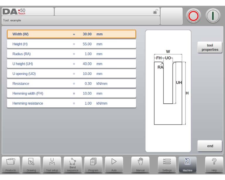
Width
The width of the tool to program.
Height
The total height of the tool. Important: this height value will be used in the bend depth calculation.
Radius
The radius of the edges of the U-opening.
U height
The height of the U-opening of the die.
U opening
The width of the U-opening of the die.
Resistance
Maximum allowable force on the tool.
Hemming width
The front width of the die, meant as support for the hem bend.
Hemming resistance
Maximum allowable force on the tool during hemming.
Interpretation of notes: classification of bending methods
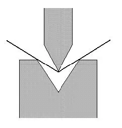
air bend
The sheet is bent to the programmed angle by bringing the punch to the required depth. The control calculates the required Y-axis position to obtain the programmed angle.
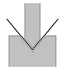
bottoming
The sheet is bent by pressing the sheet between the punch and the die. The control assumes the bottom of the die as required Yaxis position.
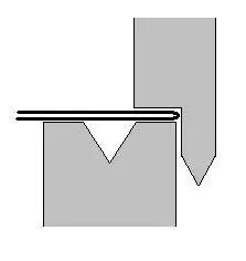
hemming
The sheet is folded in two. This is possible after the sheet has been bent into a sharp angle in a previous bend. The control calculates the precise Y-axis position for this action: the surface of the die plus twice the sheet thickness.
Y-axis positioning can be adjusted by programming a 'hem opening'.
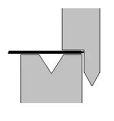
hemming & bottoming
The same as hemming, but now the control assumes the top of the die as required Y-axis position. The folded sheet is pressing between punch and die.
Note 1
The hemming bends are shown here with a special hemming punch, but this is not required.
Note 2
When bottoming operation is selected, the end of bend position of the Y-axis beam depends on the working force. If however the force is sufficient for the beam to go to the calculated Yaxis end of bend position, the beam stroke will be limited by the position value.
Summary
The above is the specific operation of how to add and set the tools to the press brake, I hope it can help you. If you have completed the above operations, you can continue to read our next article:
