Delem DA53T Controller is a commonly used digital control system on hydraulic press brakes produced by KRRASS.
Preface
This manual describes the operation of the Delem DA53T Controller and is meant for operators who are instructed for operation of the total machine.
Delem Limited warranty
• This manual does not entitle you to any rights. Delem reserves the right to change this manual without prior warning.
• All rights reserved. The copyright is held by Delem. No part of this publication may be copied or reproduced without written permission from Delem BV.
Version history
The control software is updated regularly to increase performance and add new functionality.
This manual is also updated as a result of changes in the control software. The following over view shows the relation between software and manual versions.
Software version Manual version Description
V1.5 V0817 first issue V1
This manual is valid for software version 1.5 and higher.
1. Operation overview and general introduction
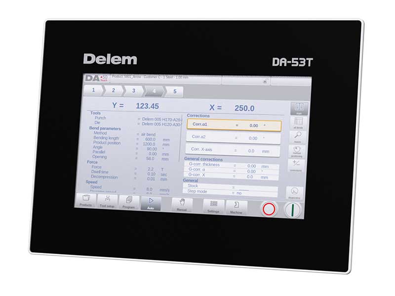
1.1. The control unit
The DA53T device looks as follows:
The precise outfit of your control may vary.
Operation of the control is mainly done over the touchscreen. A description of the functions and available touch controls is given in the next sections of this manual, aside of the description of the specific functions.
This user manual focuses on the control software and related machine functions.

1.2. Front control elements
The Start and Stop button, integrated in the touch screen user interface.

1.3. USB connectors
At the right side of the control a USB port is available for connection of external devices, such as a memory stick or an external keyboard or mouse.

1.4. Operation and programming modes
The DA-Touch control's main screen looks as follows:

Depending on the navigation button which is active, the screen will differ. The above main screen will appear having the Products function active.
Just by tapping the various modes, the specific mode will be selected.
The structure of the main screen is as follows:
Title panel
In the top the title panel is always shown. In this area you can find logo information, which product is loaded, the active bend, selected subdirectory and (when activated) the service row. Also machine indicators can be found here.

Information panel
In the information panel all functions and visualisation related to the selected modus are displayed and can be found.

Command panel
The command panel is part of the Information panel and is the location where the controls related to the Information panel can be found.
Navigation panel
The Navigation panel is the area where all the major modes can be found. This area is always visible. The controls, large buttons with icons, can be used to directly switch from one mode to the other.
![]()
Explanation of the main modes / navigation buttons

1.5. Getting started
1.5.1. Introduction
In order to obtain a bend program for a product, the control offers the possibility to create a product drawing and calculate a valid bend sequence for the product. With this information, a product program is generated.
This is done with the following steps:
- Go to the Products mode in the navigation panel and start a new product by tap ping New Product.
- Enter the product properties and start to draw a 2D product profile in the Drawing mode.
- Check the tooling, modify or make a new set-up in the Tool Setup mode.
- Use the Bend Sequence mode to determine the bend sequence by calculating it.
or manually modifying it upon your own idea's. - When required modify the numerical CNC program via the Program mode.
- Tap Auto and press the Start button in order to produce the programmed product.
1.5.2. Preparations
Before product programming can be started, the following preparations must be made.
• The correct material properties must have been programmed in the Materials library. You can find this on the Materials page in the Settings mode.
• The correct tools must be programmed in the Tool Library. Tools are necessary to create a CNC program. You can find the libraries for the different types of tools in the Machine mode.
1.5.3. Create a drawing
The control offers the functionality to create a drawing of the intended product. With this drawing application, tap Drawing in the navigation panel, a 2D profile is created. At this stage, there is no calculation of bends or dimensions: any profile or drawing can be created.
The drawing method on the Touch screen control is based on:
- Sketching
- Value setting
Sketching
The product as well as tool shape Sketching can be done by tapping on the screen in the different directions the drawing must have. The application will follow the tapping with drawing a line between the indicated points. The last point of the design will show always a big red dot. When the drawing dot is on the screen you can hold your finger on this position and move the finger across the screen to move the connected line in another required direction or make the line length longer. This method is the so-called 'Dragging' facility. The length and angle value will be visible on the screen and can be adjusted to be exact or close to the requested value.
Value Setting
Once the product or tool is drawn in the Sketching method the exact values of line lengths and angles can be optimized by the Value setting method. Just tap 2 times on the value of the line length or angle to change and the keyboard will pop-up. The value can be entered in 2 ways of confirmation:
- Enter function
- Enter-Next function
The Enter function will close the keyboard after entering the value. The Enter-Next function will enter the value on the line or angle to change and the keyboard will remain opened for the next programming step.
In case the typed value is erroneous, the “undo” button right from the input field can be tapped to return to the original value or the backspace key on the keyboard to delete the last typed character.
Zoom Function
By pinching the screen with two fingers simultaeously one can zoom in and out on the drawing, tool or machine visualisation. By spreading fingers the system will zoom-in, by bringing fingers nearer to each other the system will zoom-out.
Fit-To-Screen
In the command icons on the side of the screen you will find a Fit-To-Screen function. This can be used when the drawing size is not clear in picture. Just tap once and the complete drawing will be sized to fit the drawing screen.
Panning
A single finger will enable panning.
Features of the drawing tool
- Graphical design of product shapes in 2D
- Scaled sheet thickness
- Auto scaling
- Horizontal and vertical projected dimensions can be entered
- Real scale tool design
- Single machine shape (pressbeam and table)
- Changing of lengths and angles
- Adding or deleting of bends
- Special bend features can be applied
- Hemming bends can be programmed
- Bumping bends can be used for big radius
- Existing products can be copied, changed and stored as a new product
- Closing dimension or highest precision tolerance selection
- Connecting 2D programs for 3D-production
1.5.4. Determine bend sequence
When the product drawing is completed, the control offers Tool setup mode to program the exact tool set-up as it is organised on the machine. After this you can select the Bend Sequence mode to determine and simulate the required bend sequence.
In the Bend Sequence mode, the control shows the product, the machine and the tools. In this menu the bend sequence can be programmed and checked visually. When a bend sequence has been determined, the CNC program can be generated.
Bending sequence computation
- Automatic computation for minimum production time
- Interactive bend sequence determination
- Manual bend sequence determination
- Collision visualization of product with tools and machine
- Free tool selection
- Assignments of turn times, backgauge speed etc.
- Blank length computation
- Production time indication
- Bending sequence simulation
- Programmable finger positions
1.5.5. Numerical program
The Program menu gives access to the numerical program and values of the active product.
There are two possibilities to create a CNC program:
- enter a numerical program, started via Products mode, tap New Program, step by step;
- generate the program from the graphical bend simulation started via the Products mode, tap New Product, via the Drawing mode. (see: Drawing mode; product drawing).
If the program is entered by hand, there is no collision check. All program values must be entered manually. The program depends on operator experience.
If the program is generated from a graphical bend sequence, the program can be visualised during production. A generated program can be edited according to operation needs.
When a drawing has been completed with a bend sequence, and the program is stored, the program is post processed and the numerical program becomes available.
The system automatically computes :
- Necessary force
- Machine adjustments such as:
- Y-axis position
- Decompression
- X-axis position
- X-axis retract
- Y-opening
- R-axes
- Z-axes
Axes positions are calculated according to the machine configuration.
1.5.6. The Auto menu and Manual menu, production modes
A product program can be executed via the Auto mode. In Automatic mode, a complete program can be executed bend after bend. In the Auto mode the Step mode can be selected to have each bend started separately.
The Manual mode of the control is an independent production mode. In this mode, one bend can be programmed and executed. It is typically used to test the behaviour of the bend system.
More information about this can be found in chapters 7 and 8.
1.5.7. Back-up data, external storage
Both product and tool files can be stored externally. Depending on the configuration, these files can be stored on a network or on a USB stick. This facilitates a back-up of important data and the possibility to exchange files between Delem controls.
1.6. Programming aids
1.6.1. Help text
This control is equipped with an on-line Help function. When the Help-button in the navigation panel is pressed context sensitive help will be provided.
![]()
To activate a help window for a parameter tap the Help button in the navigation panel. A pop-up window appears with information on the active parameter.

This Help window contains the same information as the Operation manual.
The help window can be used as follows:
You can scroll through the text sliding one finger in the desired direction. By tapping on the lower or upper part of the screen Previous Page / Next Page can be used to browse through the help text.
The Index function helps to jump to the table of contents. Hyperlinks in the table help to directly navigate to the desired topic.
Tap End to close the Help window.
1.6.2. Listbox functionality
Several parameters on the control have a limited number of possible values. When selecting such a parameter, by tapping the parameter line on the screen, the list of options will open up near the position where you tapped the line, and the desired value can be selected.
To undo the selection and the opened listbox, tapping outside the box will make it close without changing the selected parameter.
To improve the focus on parameters, and to ease the use while programming, the parameter zoom function will enlarge specific parameterlines when being programmed.
eg. force in Program mode, the force lines will expand giving them better focus while fine tuning.

When selecting any other parameterline, the previous selection will be reduced and zoomed out again, as the newly selected parameterline will be zoomed in at.
1.6.3. Navigation
Within some modes, the program screens are divided into tabs.

The tabs can easily be selected by just tapping them. When a tab is not completely visible or not visible at all, just by dragging the tab row horizontally, the desired tab can be "pulled" in sight and be selected.
1.6.4. Text input and editing
The cursor can be used to enter a specific value or text within an existing input. Just tap at the desired position to do so. The cursor will appear and input will be added there.
1.6.5. Typing alphanumeric characters vs. special characters
Both alphanumeric characters and special characters can be used throughout the control. A full on-screen alphanumerical keyboard will pop up when required.
When editing a field which is pure numeric, the alphanumeric characters will be hidden. For fields which enable to use alphanumerical strings, the keyboard is completely available.
Special characters as ? % - can be found using the special character button on the left-lower side of the keyboard.

Special characters (like á, à, â, ã, ä, å, æ) are supported by the on screen keyboard by keeping a character (like ‘a’) pressed.

1.6.6. Messages centre
When messages are displayed coming from PLC, Safety systems or the Sequencer, these messages can be ‘send’ to the 'Messages centre'. When a message is displayed simultaneously the message centre symbol is shown in the top row of the page header, next to eg. the keylock symbol. When tapping this message centre symbol the messages are taken from the screen, giving way for normal programming and editing. When tapping again the actual messages are shown.
When messages are in the background, the message centre symbol has an extra indicator to show new incoming messages which are not yet shown.

1.6.7. Keylock function
To prevent for changes to products or programs, the keylock function offers the possibility to lock the control.
There are two levels of locking the control. Program Lock and Machine Lock.
- In Program Lock, only a product can be selected and executed in Automatic mode.
- In Machine Lock, the machine is locked and the control can not be used.
To lock a control just tap the lock symbol in the top of the screen. Depending on the code which is used, the control will be in Program Lock or Machine Lock. Program Lock wil show a closed lock in grey. Machine lock will show the same lock but colored (red).

Lock symbols when Program Lock is active will also appear behind parameters to show the lock is active and modification is not possible.
To unlock the control, tap the lock symbol and enter the appropriate code. After entering, the lock symbol will show it is unlocked and the lock symbols behind parameters will disappear.

Codes can be changed upon desire. The procedure to manages codes can be found in the Installation manual.
1.6.8. Manual positioning
On the manual positioning page in Manual mode and Automatic mode a slider at the bottom of the screen can be used to position the axis. The distance moved with the slider determines the speed of the axis. When the slider is released, the axis stops. The buttons at each end of the slider can be used to fine-tune the axis position. When "sliding" the beeper gives feedback that the axis is moving.

1.6.9. Software versions
The version of the software in your control is displayed at the System Information tab in the Machine menu.

Example of version number:
V 1.2.3
V stands for version
V 1.x.x is the major version number
V x.2.x is the minor version number
V x.x.3 is the update version number
The major version number is increased when new major features are added to the software. These software changes require additional introduction and could change the normal working order. The minor version number is increased when new features and enhancements are integrated which do not change the working order. The update version number solely is used for software changes when corrections are needed in the existing software version.
2. Products, the product library
2.1. Introduction
In the Products mode existing, previously produced, products can be selected to start production or for modification in order to make a similar product. To start making a new program New Program can be used from this mode.

2.1.1. The main view

In Products mode an overview is given of the program library on the control. In this mode a product program can be selected (loaded). After that a program can be modified or executed.
Each item in the list consists of its Product ID, the Product Description, the Number of bends in the product and the Date it was last used or modified.
If a product program is already active its ID is shown in the top of the screen. A program can be loaded by tapping the product ID or any other part of the product's line.
When there are more products than can be visualised in the screen simply drag the list in the upward direction until the product is visible. From then again a single tap on the product selects the product and activates it in the control.
2.1.2. Product selection
To select a product a single tap will do. The product will be selected and loaded into the memory. From here production can be started by tapping Auto. Also navigation can start through the Tool Setup and the numerical Program.

2.1.3. New Program, starting a numerical program
To start a new numerical program tap New Program.
After New Program is chosen, the programming starts with its general details like e.g. Product ID, Thickness and Material.

2.1.4. Edit, Copying and Deleting a product or program
To delete a product in the Products mode select a product by tapping it. It will be selected. After that tap Edit and use Delete. To finally delete it confirm the question. To delete all programs at once, tap Delete All.

To copy a product select a program and tap Edit and use Copy. After this the name of the product can be programmed and the copy will be done. The copied product will be an exact copy including tool setup.

2.1.5. Product Rename
Products can also be renamed.This can be done in one single step: Rename allows the user to give it a new name.
To rename a product select a program and tap Edit and choose Rename from the list. For Rename a new name can be given.
3. Tool configuration
3.1. Introduction
To edit or modify a tool setup for the product, select the product from the library and use Tool Setup.

3.2. Standard procedure
When the function Tool Setup has been activated, the screen shows the active machine setup. Both punch and die can be selected from the tool library.

The Upper and Lower tool, resp. Punch and Die, in the machine are shown and can be changed.
3.3. Tool selection
When selecting tools, both upper and lower tool (resp. punch and die) can be selected from the tool library.
Tap Select Punch or Select Die to change tools to the configuration.
4. Product programming
4.1. Introduction
To generate or modify a numerical program, start a new program from the Products mode or use Program to enter directly.


To edit an existing CNC program, select a product in the Products overview and select the navigation button Program. When starting a new program, select New Program and after giving in the main product properties and tool setup, the system will automatically switch to Program.
In both cases, a screen as shown above should appear. Programming and changing data is done in the same way in both cases.
The main screen shows the existing numerical program or, when starting a new program, the first to be programmed bend. The bend selector in the top of the screen can be used to navigate thru the bends. The indicated bends can be tapped to easily select the desired bend data. At the side of the main screen views and functions are indicated with command buttons.
Functions
Following modes / functions are available:

4.2. Program mode, parameter explanation
The main screen shows the available bends and from this main screen, from every available bend, specific paremeters can be viewed and edited.
The product ID and product description are displayed in the top row on the screen.

4.2.1. Bend parameters
Method
Select the required bending method. The control supports the following standard methods:
- air bend
- bottoming
- hemming
- hemming & bottoming
Bend methods

Note 1: The hemming bends are shown here with a special hemming punch, but this is not required.
Note 2: When bottoming operation is selected, the end of bend position of the Y-axis beam depends on the working force. If however the force is sufficient for the beam to go to the calculated Y-axis end of bend position, the beam stroke will be limited by the position value.
Bending length
Length of the sheet between tools.
Effective bend length
The effective length of the sheet between tools, which is used for the calculation of the force and the crowning device (if present). This effective bend length is calculated from the product geometry; for additional bends and simultaneous bends this calculated value is the sum of the separate bend line lengths.
Product position
The absolute position value of the product in the Z-direction. Left machine side is reference position zero.
Angle
The required angle of this bend. This parameter only appears if angle programming is selected with the parameter ‘Angle sel.’ and the bend method is an air bend.
Hem opening
The hem bend can be made with a certain opening distance between the 2 flanges. The hem opening value will be used calculating the beam position in the hemming process.
By default this parameter has the value of the Settings mode parameter Default Hem Opening.

Y-axis (Bend position)
The required Y-axis position for this bend. This parameter only appears if absolute programming is selected with the parameter ‘Angle sel.’ This parameter also appears if the bend method is bottoming and/or hemming.
Mute
Sequence point at which the Y-axis is switched from fast closing speed to pressing speed. The value programmed here is the distance of the mute point above the sheet.
By default, the mute value from the programmed die is used. Whether or not this parameter is present depends on machine settings.
Parallel
Difference of left- and right hand side cylinder (Y1 and Y2). When positive, right hand side lower. When negative, right hand side higher. The programmed value is active below the clamping point.

Opening
This parameter results in a certain gap opening between the punch and the die after the bend. A positive value is the gap opening above Mute, a negative value below Mute.
When you want to limit the handling time of the product you can program a small positive or a negative value.
4.3. Edit / view modes
4.3.1. All Bends
When the function All Bends has been pressed, a complete overview of the bends appears.

From within this screen, the complete CNC program can be edited. All bend parameters can be edited within the table and bends can be swapped, moved, added and deleted.
The available columns can be scrolled by finger movement / swipe.
4.3.2. Change tools
To change the tools the Tool Setup menu can be used. If the tool setup needs to be changed for just one bend step, the Change Tools button can be used. The control will always ask if the changes are to be done on the whole setup or just for one bend. If the whole tool setup is required, automatically the Tool Setup menu will be switched to.
4.3.3. Product properties
To change the main product properties tap Product Properties. These parameters of the program are the same for every bend of the program (main data of program).
4.3.4. Add bend
To add a new bend after the last bend. When pressed, the last bend is copied and added after the last bend.
4.3.5. Bumping
From pure numerical programs a single bend step can be changed into a bumping bend.

4.4. Programming parameters
Parameters in program mode can be programmed one by one. The effect of the parameter on other parameters is automatically computed. The relation between parameters is visualized with a symbol and a background color.

5. Automatic mode
5.1. Introduction
By tapping the navigation button Auto the control is switched to the automatic production mode.

In auto mode with the active program, production can be started. After entering Auto, the Start button can be pressed and production can begin.

The automatic mode executes the program automatically bend by bend after pushing the Start button. When selecting a different product in Products mode, which is in the library and has already been used for production, one can immediately switch to Auto and start production. Every time after a different bending program is selected you must check your tools and tool positions in your machine. This is also indicated with a ‘check tools’ warning message when you enter the automatic mode.
In the header of the Auto mode screen the selected product is displayed along with the product description. At the top of the screen the bend selector shows the available bends in the program. By tapping the prefered bend the bend can be selected. The start button can be pressed to start from this bend. The details of the selected bend are shown in the available views
The repetition of a bend and the connected programs, when applicable, are shown in the header of the screen. A connected program is also indicated in the bend selectors last position.
5.1.1. Auto mode, parameter explanation
Following is a list of the available parameters in Auto mode.
5.2. View modes
The auto mode screen is offering a diversity of views which, depending on ones production methode, can be chosen. When selecting auto mode for the first time, the main screen will appear. On the right side of the screen the available view modes can be selected.
Following view modes are available:

The appropriate view can be switched from and to, not changing the bend data. The Start will not jump to Stop while switching view modes.
5.2.1. Main
Main view shows the numerical data of the bend along with the corrections. The corrections can be programmed here.

Both columns can be scrolled to see all data.
Bend selector
The bend selector in the top of the screen can be used to navigate thru the bends. The indicated bends can be tapped to easily select the desired bend data.

5.2.2. All bends
The all bends view mode shows a table including all bend data. The bends are shown row wize and the columns display all bend parameters.

5.2.3. Macro
With macro view mode, the control switches to a view with only large axes values on the screen. This view can be used when working a little remote from the control, still able to read the axes values.

Next to the target position (programmed) also the actual position of all axes can be followed.
5.2.4. Manual positioning
In manual positioning view mode the axes values are shown at large. Axes can be selected and while selected the position can be controlled by moving the slider, on the bottom of the screen, out of its middle position. When releasing the slider it will return to its middle position automatically.
The teach indicator:

When the teach indicator arrow is pressed, standing in between actual value and programmed value, the value is tought to the program step.

5.2.5. Corrections
In this view mode all corrections of all bends are shown. You can browse through all corrections and change them as you see fit. If a correction for α1 is entered then this value is, dependent on the settings parameter 'Angle correction programming', copied to the correction for α2, or keeping the delta between both corrections, or not influencing the correction for α2. Different corrections for α2 can be entered in the field itself.

The column ‘Stored correction’ is only available when the Angle correction database has been activated. When activated, the column ‘Stored correction’ shows for each bend the correction value that is present in the database. A blank entry in this column means the database does not have a correction value for this type of bend. When a new correction is entered, it will be copied to the database automatically.
The markers ‘>’ indicate bends that have the same value.
All From Stored serves to copy corrections in the database to the current program: corrections in all bends are adjusted according to database values.
Calculate corrections, programming of measured angles
To calculate the corrections from measured angle values, one can use the “calculate corrections” function in the correction window. Calculate corrections will open a separate window in which, upon choice, the measured angle(s) can be programmed.

From the programmed value the control will determine a correction. The proposed result can be seen in the window itself. In the top of the window the programmed angle is shown, in the bottom of the window the resulting corrections are shown. When selecting accept, these values will be transferred to the main corrections screen.
When only one measured angle value is entered, the other values will be copied equally. If there are separate left, right or even middle values, these can be entered as well. The appropriate correction values will be determined from the entered values. The middle measured angle, if applicable, is transferred to an absolute crowning correction.
Axes corrections can also be edited in the main screen. When there are multiple axes available this special view mode can be switched to for all axes corrections.
5.2.6. Diagnostics
The diagnostics view mode is meant for service purpose mostly. In diagnostics the activities of independent axes can be monitored. I/O on the control system can be followed. In rare situations this information can be helpful to diagnose operation during the bending proces.

5.3. Bumping correction
In case of a selected bumping bend a general correction for a bumping bend can be entered. This function is only available if a product is loaded that contains a bumping bend.
With Bumping Corr. a new window appears in which the correction can be entered.

When the general correction of an angle is altered, all individual corrections are recalculated. When any of the individual corrections is altered, the general correction is recalculated.
Bumping corrections can be programmed independently for both sides, α1 and α2.
If a bumping correction for α1 is entered then this value is, dependent on the settings parameter ‘Angle correction programming’, copied to the bumping correction for α2, or keeping the delta between both bumping corrections, or not influencing the bumping correction for α2. Subsequently all separate corrections for α2 are recalculated. To change correction values of α2, use bumping correction α2 or one of the separate corrections of α2.
6. Manual mode
6.1. Introduction
By tapping the navigation button Manual the control is switched to the manual production mode.

In manual mode you program the parameters for one bending. This mode is useful for testing, for calibration and for single bends.

Manual mode is independent from Automatic mode and can be programmed independently of the programs in memory.
In the top of the Manual mode screen you can find the Y-axis and the main X-axis current position. All other axes and functions are listed one by one in the two columns below.
When these Y-axis value and X-axis value are highlighted it means that the reference markers of these axes have been found and that they are positioned correctly referred to their programmed values.
6.1.1. Manual mode, parameter explanation
Following is a list of the available parameters in Manual mode.
Bend parameters
Method
Select the required bending method. The control supports the following standard methods:
- Air bend
- Bottoming
- Hemming
- Hemming & bottoming

The bend methods have been explained in more detail in the Program mode.
Bending length
Program the bending length of the sheet.
Product position
The absolute position value of the product in the Z-direction. Left machine side is reference position zero.
Angle
Angle to bend.
Corr.α 1, Corr.α2
Correction on angle to bend.
The angle correction should be entered as following examples indicate:
Programmed value of 90 degrees.
Measured value of 92 degrees.
-> Then it is required to program Corr. with -2.
Programmed value of 90 degrees.
Measured value of 88 degrees.
-> Then it is required to program Corr. with +2.
Hem opening
The hem bend can be made with a certain opening distance between the 2 flanges.
The hem opening value will be used calculating the beam position in the hemming process.
By default this parameter has the value of the Settings mode parameter Default Hem Opening.

Corr.Y
Correction on the Y-axis position, in case bottoming has been selected.
Y-axis
The programmed or calculated Y-axis value to realise a certain angle.
Mute
Sequence point where the Y-axis is switched from fast closing speed to pressing speed. It is programmed here as a Y-axis position value. The programmed value is the Y-axis point above the sheet.

Parallel
Difference of the left- and right hand side cylinder (Y1 and Y2). When positive, the right hand side is lower. When negative, the right hand side is higher. The programmed value is active below the clamping point.
Opening
This parameter results in a certain gap opening between the punch and the die after the bend. A positive value is the gap opening above Mute, a negative value below Mute.
When you want to limit the handling time for the product you can program a small positive or a negative value.
Force
Force
The programmed force applied during pressing.
Dwell time
Hold time of punch at the bending point.
Decompression
Decompression distance after the bending to release the working pressure from the system.
Speed
Speed
Pressing speed, the speed of the Y-axis during bending.
Decomp speed
The decompression speed is the programmable speed of the beam during the decompression distance.
Functions
Wait for retract
In case of a retract, let the Y-axis wait until the retract is finished, yes or no.
- No: the retract is started when the Y-axis passes the clamping point, the Y-axis does not stop.
- Yes: when the Y-axis reaches the clamping point, the Y-axis is stopped and the retract is started. When the retract is completed, the Y-axis moves on.
Product properties
- Thickness
Program the thickness of the sheet. - Material
Selection of one of the programmed materials, which are used to calculate the bending depths. The control contains 4 pre-programmed materials. In total, 99 materials can be programmed on the control. The materials can be programmed on the Materials page in the Setting mode.

Tools
Punch
The name (ID) of the selected punch. Tap to modify or select from the punch library.
Die
The name (ID) of the selected die. Tap to modify or select from the die library.
Auxiliary axes
Auxiliary axis
If you have one or more auxiliary axes (for instance an X-axis, R-axis or Z-axis) the parameters of these axes appear here.
Retract
The retract distance of the axis during the bend. The "backgauge retract" is started at the pinching point.
Speed
Speed of the axis in the current bend. Speed can be programmed in a percentage of the maximum possible speed.
The above mentioned parameters can be programmed and modified as required. After pushing the Start button the programmed parameters are active.
6.1.2. Tool setup
The programming of the tool setup in Manual mode is similar to programming the tool setup which is used in Automatic mode. Despite the fact that both modes do not share the same tool setup (enabling the usage of a complete different tool setup), the tool setup of Automatic mode could be used in Manual mode as well.
While switching from Automatic mode to Manual mode, the control offers the user to use the same tool setup in Manual mode and thus also the user is warned that in case differently programmed, one should be careful.

In the tool setup menu tools can be added or removed, similar to the main Tool Setup mode as described in chapter 3.
Adding tools ( Punches / Dies )
Same as in Tool Setup, via the Add function tools can be added.
6.2. Programming parameters & Views
Parameters in manual mode can be programmed one by one. The effect of the parameter on other parameters is automatically computed.
The relation between parameters is visualized with a symbol and a background color.

When an information symbol is shown with parameters after an editted value, this parameter was changed due to the last changed input.
![]()
A star symbol is shown with parameters if the value of the parameter differs from the calculated value by the control. This can be helpful if a value is intentionally programmed different or if the value of a parameter is limited by the parameters limits.
![]()
An error symbol is shown with parameters if the value cannot be correct according to the currently programmed values. This, eg. when a hemming bend is programmed with no hemming tools programmed.
![]()
View
The command buttons on the right side of the screen give access to other views. Next to the Main view, there are Macro, Manual Positioning, Corrections as also a Diagnostics view.

6.3. Macro
With Macro the control switches to a new view with only large axes values on the screen. This view can be used when working a little remote from the control, still able to read the axes values.

6.4. Manual movement of the axes
6.4.1. Movement procedure
To move an axis to a specific position manually, the slider at the bottom of the screen, can be used. After tapping Manual Pos in the main screen of Manual Mode, the following screen appears:

Within this mode, any of the shown axes can be moved by moving the slider out of its middle position. The procedure for moving the axis depends on the axis you wish to move. When releasing the slider it will automatically return to its middle position.
Auxiliary axes
The control must be stopped (the Stop button is on).
First select the desired back gauge axis, you will see the cursor at the required axis.
Then you can move the axis by moving the slider.
Y-axis
The pressbeam can be positioned manually in the same way as the auxiliary axes.
However, for the Y-axis several conditions must be met:
- The control must be started (the Start button is on).
- The 'adjust' function must be active. If this function is not active a message is
shown in the upper right-hand corner. - The Y-axis must be below mute-point.
- A pressing command must be given to the CNC.
6.4.2. Teach
To teach the control, taking over a position found by manual moving an axis, a simple procedure can be used.
When you have moved an axis to a certain position with the slider, you may want to store this position. To do so, tap the axis name in the Programmed column. The actual axis value (left side) will appear in the programmed axis field (right side).
When you return to the standard screen of manual mode, the axis parameter will have the recently taught value.
6.5. Corrections
In this view mode the corrections for the bend programmed in Manual mode are shown. Since this is always a single bend, a single line will be shown.

The programmed corrections can be verified here similarly to the corrections in Automode.
Entries in the correction database and for initial correction can also be monitored in this screen. Since these are of significant influence on the bend result, access to the database can be used to modify. This can also be useful while finding appropriate corrections with testbending and storing the found results in the database.

6.6. Diagnostics
When tapping Diagnostics, the control switches to a view which shows axes states. In this window, the current state of available axes can be observed. This screen can also be active while the control is started. As such, it can be used to monitor the control behaviour during a bend cycle.

6.6.1. I/O status
When tapping on the I/O tab in the Diagnostics, the control switches to a view with the state of inputs and outputs. In this window, the current state of inputs and outputs can be observed.
This screen can also be active while the control is started. As such, it can be used to monitor the control behaviour during a bend cycle.

6.6.2. Zoomed I/O
When tapping on one or more (up to 5) pins an extra page Zoomed IO is created with an enlarged view of the selected IO; selected pins will be shown in large, enabling distant monitoring.

7. Settings
7.1. Introduction
By tapping the navigation button Settings the control is switched to Settings mode.

The Settings mode of the control, which can be found in the navigation panel, gives access to all kind of settings which influence the programming of new products and programs.
Default values and specific constraints can be set.
The settings are divided across several tabs logically organizing the different subjects. In the following sections the available tabs and detailed settings are discussed.

Navigation through the tabs can be done by just tapping them and selecting the required item to adjust. Since there can be more tabs than the screen can show in one view, dragging the tabs in horizontal direction enables to view and select all available tabs.
7.2. General
Select the required tab and tap the parameter to be changed. When parameters have a numerical or alphanumerical value, the keyboard will appear to enter the desired value. When the setting or parameter can be selected from a list, the list will appear and selection can be done by tapping. Longer lists allow scrolling vertically to check the available items.
Inch/mm-select
Select to use either millimeters or inches as the unit to be used.
Ton/kN select
Select to use either Ton or kN as the main unit to be used for all force data.
Resistance per m/mm selection
Select to use the resistance either per meter or per millimeter.
Language
The user interface language can be selected from the list. There are more available languages than initially shown. Scroll vertically by dragging the list up en down to see all available languages. Tap to select the desired language for the user interface.
(For languages using special, non standard alphanumerical characters, the control will reboot.)

Keyboard layout
Upon choice one can select Qwerty, Qwertz or Azerty keyboard layout.
Key sound
Switch the sound function of the input panel on or off.
Message sound
Parameter to enable/disable the sound function for messages dependent on the message type.
all messages => sound on for all messages.
errors + warnings=> sound on for errors and warnings only.
errors => sound on for errors only.
none => sound off for all messages.
Command panel side
Switch the command panel to the left side of the screen.
7.3. Materials
In this tab, materials with their properties can be programmed. Existing materials can be edited, new materials can be added or existing materials deleted. A maximum of 99 materials can be programmed on the control.

For each material 3 properties are present and can be viewed and edited.
- Material name
Name of the material, as it will appear in the programming screens. The maximum allowed length of the material name is 25 characters, the name must begin with a character (not a numeral). - Tensile strength
Tensile strength of the selected material. - E module
E-module of the selected material. - Strain hardening exponent
The Material strain hardening exponent, n, is a material property that should be provided by the supplier of the material, just like the tensile strength and E-module.
Entering the correct values for this parameter will give an improvement of the inner radius calculation and thus a more accurate bending depth and bend allowance calculation.
In its turn a more accurate bend allowance will result in more accurate back gauge positions.
Initially the value is set to _.__ for all the materials. This means that the parameter n is not active. The result of all calculations is the same as with previous software versions.
The range of the parameter n is 0.01 – 1.00.
For example, a typical value for mild steel is 0.21.
When 0 is entered again, the value will be reset to _.__ - Calculate n
The Material strain hardening exponent, n, is a material property that should be provided by the supplier of the material, just like the tensile strength and E-module.
As an alternative, it can also be derived from the bend allowance. A test bend has to be made in Manual mode. When you switch to the materials table and tap the button ‘calculate n’, the following window will appear on the screen:

The parameter values are taken from the Manual mode screen. After the bend the resulting side length should be measured and entered in the window. With the difference between the programmed X-axis position and the measured side length the bend allowance and the strain hardening exponent (n) are calculated.
The accuracy of the calculation depends on the accuracy of the sheet thickness, tool parameters and side length measurement.
The materials are initially listed according to their material number, which is shown in the first column (ID). The list can be sorted according to the different properties by tapping the title of the column. The materials will be sorted in ascending or descending order of that property.
To change an existing material, select the relevant line and change the values as you see fit.
To delete an existing material, select the relevant line and use Delete Material. This will erase the values.
To program a new material select an empty line and start programming its values.
7.4. Backup / restore
This tab offers the possibilities to backup and restore products, tools as well as settings and tables. When products or tools originate from older control models, the DLC-file format products and tools can also be restored using this specific restore function.
For materials a specific backup and restore are available here.
Tools and products can be backupped and restored according to the following procedures.
The procedures for saving or reading data are similar for all types of backup media: e.g. network or USB stick.

The actual backup directory consists of a device (USB stick, network) and a directory.
The choice of devices depends on which devices have been connected to the control.
If necessary, directories can be created and selected. The backup locations for storage of products and tools can be set independently.
7.4.1. Product backup
To make a backup of programs to disk, choose ‘products’ in the Backup section on the Backup/restore page.

When the initial backup directory has been set, the products backup screen appears.

In the backup screen the products in the selected directory are shown.
Basic functions to change the view can be chosen similarly to the Products mode.
This enables to easily find the required products to be backupped.
At the top of the screen, the current source location is shown as well as the backup location.
To backup a product, select it by tapping, in the list. The backup marker will appear to confirm the backup action. If a product file with the same name is present on the backup location, a question is offered whether or not to replace that file.
To backup all products at ones, tap All.
The source where the products are located which have to be backupped can be changed with Source Directory. The directory browser appears and the desired source directory can be navigated to.
The directory where the products which need to be backupped need to go can be changed as well. With Backup Directory the directory browser appears and the desired destination directory can be navigated to.
7.4.2. Product restore
To restore programs to the control, choose ‘products’ in the Restore section on the Backup/ restore page.
When the initial restore directory has been set, the products restore screen appears.

In the restore screen the products in the selected directory are shown.
Basic functions to change the view can be chosen similarly to the Products mode.
This enables to easily find the required products to be restored.
At the top of the screen, the current restore source location is shown as well as the location on the control to restore to. To restore a product, select it by tapping, in the list. The restore marker will appear to confirm the restore action. If a product file with the same name is present on the control, a question is offered whether or not to replace that file.
The source location where the products to be restored are coming from can be changed with Restore Directory. The directory browser appears and the desired restore directory can be navigated to.
The directory where the products which need to be restored need to go can be changed as well. With Destination Directory the directory browser appears and the desired destination directory can be navigated to.
7.4.3. Tool backup
To make a backup of tools to disk, choose ‘tools’ in the Backup section on the Backup/restore page.
When the initial backup directory has been set, the tools backup screen appears.

With this menu a back-up of tools on the control can be made: punches, dies or machine shapes. The procedures for a tool back-up run similar to the procedures for a product backup.
7.4.4. Tool restore
The restore procedures for tools run similar to the procedures for a product restore.
7.4.5. Backup and restore for Tables and Settings
To backup user specific settings and tables the Backup/restore tab offers specific functionality. The procedure is again similar to the backup and restore of products and tools.
The special function All will automatically execute all steps sequentially for either Backup or Restore (Products + Tools + Tables + Settings).
7.4.6. Directory navigation
When Backup Directory is used, a new window appears with a list of available backup directories.

In this window you can browse through the directory structure of your backup device. To select the directory you are currently in, tap Select.
To change from one device to another, tap the highest level, and from there select the proper device and choose the correct subdirectory.
If a network connection is available you must first select Network and subsequently one of the offered network volumes. After that it works similar to other devices.
You can make new subdirectories or delete existing ones by tapping Make Subdir and Remove Subdir. If there are subdirectories present, just tap it to move to the required directory and tap Select to select it.
7.5. Program settings

Angle correction database
Parameter to enable the database with angle corrections.
Angle corrections are entered in production mode (Automatic mode). These corrections are stored in the product program.
The Angle correction database enables the possibility to store these corrections in a database. In this way corrections that have once been entered for certain bends remain available for future use in other products.
With this setting enabled, the control checks during production whether corrections for similar bends are present in the database. If corrections for certain bends are available, then they will be offered. On other occasions, corrections can be interpolated and offered.
The correction database is adjusted by entering new corrections during production.
When the database is enabled with this parameter, all new-entered corrections are stored in the database.
When searching for similar bends, the control searches for bends that have the same properties as the active bend. The following properties of a bend are compared:
- Material properties
- Thickness
- Die opening
- Die radius
- Punch radius
- Angle
The first five properties of a bend must be exactly the same as the active bend to start a comparison. If the angle is the same as the angle of the active bend, the correction is offered. If the angle of the active bend has a maximum difference of 10° with two adjacent bends, a correction is interpolated from these two bends. If the difference of the corrections of the two adjacent bends is more than 5°, there will be no correction offered.
Initial angle correction
To program relative small angle corrections the initial correction database is available.
This parameter is independent on the parameter “Angle correction database”.
The initial correction is only visible and programmable on the corrections page in Automatic mode and Manual mode. On the main page in Automatic mode and Manual mode the initial correction is not visualized. The total correction is the sum of the visualized correction and the initial correction.
Example:
– Program an angle correction of -8 degrees.
– Program an initial correction of -6 degrees. Now the total correction remains unchanged: the visualized correction is changed from -8 degrees to -2 degrees.
disabled => no initial angle corrections programmable.
enabled => initial angle corrections programmable on the corrections page
General angle correction programming
To program general angle corrections which are used in all bends of the program.
These angle corrections are not related to specific bend angles and therefore not stored in the angle correction database.
disabled => no general angle corrections.
enabled => only G-corr. α1.
α1 and α2 => G-corr. α1 and G-corr. α2.
Manual mode store angle corrections
To enable the storage of angle corrections programmed in Manual mode. Corrections can be derived from bend results in Manual mode which later can be used during product programming.
Angle correction programming
Parameter to switch between copying or keeping the delta values or changing independently when changing angle corrections in production mode.
copy => copy Cα1 to Cα2 when changing Cα1.
delta => keep delta between Cα1 and C2 when changing Cα1.
independent => change Cα1 and Cα2 independently.
X correction programming
Parameter to switch between copying or keeping the delta values or changing independently when changing the X-axis corrections in production mode.
copy => copy CX1 to CX2 when changing CX1.
delta => keep delta between CX1 and CX2 when changing CX1.
independent => change CX1 and CX2 independently.
Only available when an X2-axis is present.
Y1/Y2 independent
Parameter to program the two Y-axes independently.
off => single Y-axis programming.
on => program Y1 and Y2 separately.
Machine ID
When there are several bending machines in a factory, it can be useful to give the control on each machine a unique machine ID.
This ID will be checked when a program is read from a back-up medium. When the machine ID does not match you must confirm to read it anyway or not. If you do not confirm the question the action will be aborted.
Machine ID check
When a product from a machine with a different machine ID is selected, a warning will appear on the screen. With this parameter this check can be disabled.
Machine description
The description as programmed here will only be used in the offline Profile-T to get an overview of the different machines available in the factory. With this information it will be more clear which machine is used in combination with this control.
7.6. Default values

Y opening default
Default Y-axis opening, used as initial value for the parameter 'opening' in a new
program.
Default pressing speed
Default pressing speed, used as initial value for the parameter 'speed' in a bend program.
Default decompression speed
Default decompression speed, used as initial value for the parameter 'decompression speed' in a bend program.
Default wait for retract
Default value for the parameter 'wait for retract' in a bend program. This parameter determines the control behaviour in a bend program.
Default step change code
Default value for the parameter 'step change code' in a bend program. This parameter determines the moment of step change in a bend program.
The step change codes have been explained in more detail in the Program mode.
Default delay time
During the postprocessing, the waiting time of the X-axis at step change is set to zero.
With this parameter you can preset a longer waiting time when needed for product handling.
Default dwell time
Default value for the parameter 'dwell time' in a bend program.
Default hem opening
The hem bend can be made with a certain opening distance between the 2 flanges. The hem opening value will be used calculating the beam position in the hemming process.
This programmed default value will be used when programming a new program in the Program mode. The starting value is 0.0mm to get the two flanges of a hem bend completely upon each other without any space between the flanges.
Default material
Default material, used as initial selection while starting a new program.
7.7. Computation settings

Data preparation bend allowance
correction off => no bend-allowance added to numerical programming
correction on => bend-allowance correction added to numerical programming
With this parameter you can choose whether or not you wish to have programmed values corrected for bend-allowance. This setting only refers to corrections during product programming in the Program mode. If a numeric program has been entered with Corrections On, the axis corrections are calculated and stored in the program. These corrections can be viewed and edited inproduction mode (see 'Auto mode').
Bottoming force factor
The force needed for an air bend is multiplied by this factor in order to obtain the bottoming force.
Z-distance
The distance from the edge of the finger to the corner of the sheet.
When an automatic Z-axis has been installed, the positions of the fingers are calculated automatically with respect to the end of the sheet.

7.8. Production settings

Stock count mode
Setting for the stock counter in production mode, to have the stock counter (product counter) count up or down.
When down counting is selected, the stock counter in production mode is decremented after each product cycle. When the counter has reached zero, the control is stopped. On the next start action, the stock counting value is reset to its original value.
When up counting is selected, the counter is incremented after each product cycle.
Down counting can be useful if a pre-planned quota must be produced. Up counting could be used to give a report on production progress.
Auto bend change mode step
This parameter can be used to have automatic step change in the bending process with the Step mode enabled.
disabled => No automatic step change (next bending parameters active) will take place. To perform the next bending you must select the new bending and press the start button.
enabled => The next bending parameters are loaded automatically but the axes will start positioning after the start button has been pressed.
Parallelism offset
An overall parallelism, valid for the complete Y-axis stroke, can be programmed with this parameter. The programmed value will be checked against the maximum allowed value during production. The parallelism which can be programmed for each bending (Y2) is only active below the clamping point. The parallelism below the clamping point is the sum of the two parameters (Y2 + Parallelism offset).
Lock touch screen when started
To enable the locking of the touch screen while the control has been started.
Pressure correction
Percentage of calculated force which actually controls the pressure valve.
Clamping correction
The position of the beam at which the sheet is clamped, is calculated. In order to have a firm clamped sheet it is possible to offset the calculated pinch point with the value here programmed. A positive value will result in a deeper position, a negative value in a higher position of the beam.
X-safety offset
Defines the safety zone (minimum X-axis value), following the contour of punch and die, which will be used in case a R-axis is mounted. This to prevent collision between finger and punch / die.
Intermediate X for Z-movement.
Temporary safe value for the X-axis, to avoid collision as a result of movement along the Z-axis. With this parameter a standard safety zone for the X-axis is defined, which is valid for all programs. The value 0 disables this functionality. This parameter should not be confused with the parameter ’X-safety offset’.
This parameter is especially useful when several dies of different sizes are placed on the machine. In that situation, this intermediate X-value should be larger than the safety zone of the largest die that is installed.

When the back gauge has to move to a different Z-position, it is checked whether the current X-position is safe. We can distinguish the following situations:
- Old X-axis position as well as new position outside the zone: X- and Z-axis movements happen at the same time, no change.
- Old X-axis position outside, new position inside the zone: back gauge is positioned on Z-axes first, the X-movement starts when the Z-axes are in position.
- Old X-axis position inside, new position outside the zone: back gauge starts along Xαaxis, Z-movement is started when X-axis is outside the zone.
- Old X-axis position as well as new position inside the zone: back gauge moves to the intermediate X-axis position, then the Z-movement is started. When the Z-axes are in position the X-movement is started to move the back gauge to its new position.
Intermediate R for X-movement
Temporary position for the R-axis, to avoid collision as a result of movement of the Xαaxis. The value 0 disables this functionality. When programmed not equal to zero this position will be active when the X-axis has to move inside the safety zone of the die.
7.9. Time settings

- Display time
Display date and time on the title panel, time only or no time at all. - Time format
Display the time in 24 hours or 12 hours format. - Date format
Display the date in dd-mm-yyyy, mm-dd-yyyy or yyyy-mm-dd format. - Adjust time
To adjust the date and time. Adjusting the date and time will also adjust the date and time of the operating system.
Learn more about our products, please visit and subscribe to our Youtube channel


Excellent bending machine system,I link delem controller