General Safety
CNC press brake CybTouch 12 controller manual is directly related to the safety and security of users. Please read it carefully.

Signs and Icons appearing in this Manual
While using this manual, you will come across the signs and icons represented here below: they are directly related to the safety and security of persons. Carefully follow this advice and inform others about it.
![]()
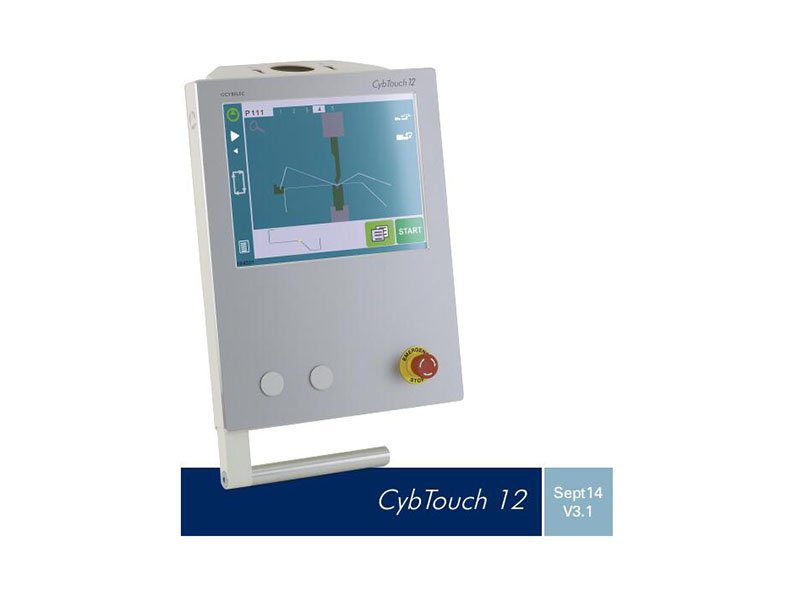
Getting started with CybTouch 12
Depending on software evolutions and the press brake controlled by the CybTouch (configuration/capabilities), the present manual may not fully correspond to the CybTouch that you currently have. However, differences are only minor.
Touchscreens are pressure sensitive.
Do not press down hard on the screen.
Pressing hard on the screen will damage the display. Such damage is not covered by manufacturer warranty!

Do not use sharp and/or pointed objects (sheet metal, screwdriver, metal pen ball, etc.) to touch the screen; only use your fingers (with or without gloves on) or a plastic pen. Make sure that your gloves do not have metal particles encrusted in the finger tips as they may also damage the screen.
Take a few minutes to practice pressing gently on the screen, you will find that the screen is very reactive and it is pleasant to use.

General navigation

Menu Button
The Menu button allows you to directly select (jump to) the desired screen. The content of the menu changes contextually.

Status Pages Zone
The Status pages zone gives access to the Status page (see page 5). This is really a zone that is active at any moment from any page (except the wizard’s).
Screen Cleaning
To clean the screen while the CybTouch is on, touch the button. Use only a damp and smooth cloth with soap or a neutral detergent.

Status page
The Status page shows the status of all inputs and outputs and axes positions of the NC.
This feature is very useful during setup or during phone service with a machine installed in the field.
This page is accessed from anywhere by pressing the Status Pages Zone (see page 4).
To exit the Status page, press on the arrow on the left.

User Preferences

Language
To browse through the available languages, simply touch Language on the screen.
Available languages are:


Length Units This parameter allows choosing between mm, inch and none for the length unit to be used in the CybTouch 12 controller.

Show Y1-Y2 position values
This function will display the Y1 and Y2 axes positions on the Bend Numerical Page (see page 14).
- When set to no, the position of axis Y1 is displayed during the beam’s movements.
- When set to yes1, the positions of the beam’s axes are displayed during the beam’s movements.
- When set to yes2, the positions of the beam’s axes are constantly displayed under the angle/beam’s position line.
Show page L-alpha num
![]()
Show bent part
This parameter, when activated, lets the operator see the state of the part before and after the bend in the Automatic Bend Sequencing (optional) page.
Materials
Touching Materials opens the Materials page, where the default characteristics for each material can be changed, or a new material can be configured.

The Materials page displays:
- Material: Selected material (here Steel).
- Default thickness for the material.
- Default sigma: Default sigma for the material (here 45).
- Displayed: If the material will be available to be selected for use (here yes).
- Thickness min/max: determines the maximum and minimum accepted thickness for the selected material.
Three predefined default materials are available (steel, stainless steel, aluminum), but others can be added.

BDC correction This parameter allows the operator to apply a permanent correction to the Bottom Dead Center position.

Clear indexation When activated, this function clears the index and the machine will search for them, as it does when turning the power on, allowing the operator to re-index its machine without turning it off.
USB Explorer When this parameter is set to yes, it is possible to browse the USB key from the USB transfer screen.
Default retraction This parameter allows defining the default value displayed in the More Page (see page 14) when activating the back gauge retraction function.
Set Clock Allows the user to set the time and date on the CybTouch.

Touchscreen Calibration
As a tall operator will tend to touch higher than a smaller one on the screen, this function allows the calibration of the touch screen, and also makes sure that it is operating correctly.

Brightness xx% Eco xx%
Here the brightness of the screen for normal mode and Eco mode can be defined:

Manual Axes Movement
In the course of setting up a machine, it is sometimes necessary to be able to move the axes manually, for example when changing the tooling. This can be done on this page.


Desynchronized Beam
When the padlock is open , it is possible to select and move (Low Speed Down movement) Y1 or Y2 only. This is an easy way to return an unsynchronized beam back to parallel to the table.
Service Page

Set Axis
Allows the operator to manually adjust the position of the back gauge (axes X and R) and the beam (axes Y1 and Y2).

Maintenance
Allows the operator to manually adjust the position of the back gauge (axes X and R) and the beam (axes Y1 and Y2).
The Maintenance page displays the hardware status of the CybTouch and lets the operator perform different maintenance actions.

Defrag
This function will rearrange the memory space of the CybTouch. Simply touch it and follow the instructions given in the yellow pop-up window.
Format
This function will erase all data in the CybTouch. Only use this with the help of a technician.
Internal backup
This function is specially designed for OEM and support.
Usually a machine parameters’ backup is made by the machine manufacturer or the company who services the machine. This backup allows a maintenance technician to restore original working parameters if necessary.
Should there be a need to restore parameters, call on a maintenance technician and follow his instructions.
Do not try to use this function unless you are in dire need.

Information The Information page displays the names and versions of the softwares installed on the CybTouch. Pressing the Advanced button shows more detailed information.

Configuration options
Touching this menu opens the following page, where one can find the computer’s identification and manage the machine’s options.

Serial number
This is the serial number of the CybTouch. It is entered at the factory at the end of the machine’s initial setup and is related to the machine’s option list.
Computer ID
This line displays an identification code that is unique to each CybTouch and guarantees, together with the serial number, a correct identification of the machine.
Option list
This function opens a yellow pop-up window where all the options installed on the CybTouch are displayed.
New option code
The function opens an alphanumerical pad where the code of the new option must be entered. The format of an option code is: ABC-DEF-GHI-JKLM
USB Transfer

Importing parts from other Cybelec NCs
CybTouch 12 controller is delivered with Cybelec’s off-line software PC1200, which controls most of the other numerical controls produced by Cybelec.
From version S1, PC1200 includes CybTouchConverter, which allows you to convert parts to the CybTouch format, and import them into your machine with the above mentioned function.
Basic Page Description
Bend Numerical Page

More Page

Available functions on the More page
The More page displays parameters related to the part, and depending on the CybTouch configuration and the type of action performed, it also displays various settings for the current bend.
Material
This is not a sequence parameter, but of course a part parameter. Each touch on the material’s name selects the next available from the list of Materials (see page 7).
Material thickness
The default thickness, defined in Materials (see page 7), is automatically displayed when changing material. It is however possible to change it simply by touching this icon.
This is also of course a part parameter.
Material sigma
The default sigma, defined in Materials (see page 7), is automatically displayed when changing material. It is however possible to change it simply by touching this icon. This is also of course a part parameter.
Back gauge retraction
The back gauge retraction can be activated/deactivated at its Default retraction (see page 8) value using this icon. It is possible to modify the value by touching it. This is a sequence parameter, meaning it can be modified with each step of the program.

Step bending
When a large radius bend has been programmed (see L-Alpha Mode, page 27), its parameters are displayed here. It is possible to modify them directly here.
Programming 99 x will automatically calculate the maximum possible step bends. The resulting value may be reduced. However, if it is increased over the maximum calculated value, the resulting radius and angle will be drastically affected.

Slow speed return
This parameter allows slowing down the speed of the beam after the bend, and is generally used when the part has a long flange and the operator tries not to let it “fall
down too fast”.
The beam will return at low speed up while the operator holds the foot pedal. It switches to high speed up when either the pedal is released or Pinch Point is reached, whichever comes first.

Dwell time
Allows defining the duration of the dwell time, meaning the time during which the punch remains at BDC before coming back up.

Force
The force is automatically calculated by the CybTouch, according to the Material, the Material thickness, the Material sigma and the Bending length. The value can also be manually modified here.
Opening (TDC)
For parts created with a profile (see TouchProfile Mode or L-Alpha Mode), this value is automatically calculated to allow the operator enough room to extract its bent part from between the tools. It is however possible to change it manually.
For part created manually (see Numerical Mode), this parameter uses the default minimum value defined in the machine parameters. It can however be programmed here.
Creating a “New part” reinitializes it to its default value.

Crowning
The crowning function is activated here. It is automatically calculated, according to the Material, the Material thickness, the Material sigma and the Bending length. If the crowning needs correction, use the Crowning (see page 29) function in the correction page.
The value can be manually changed by operator. It will however be automatically recalculated if any of the values used for its calculation is changed.

Back gauge finger type
The back gauge dimensions are defined in the machine parameters. This function allows browsing through the available support and stop positions of the back gauge. This function may be available, or not, according to the machine configuration.
Punches


How to create or modify a punch?
If no punch is yet created, the punch will have no name (??? is displayed). If a punch already exists, then the last punch used will be selected, here 60_N (modifications will not alter the existing punch as they will be saved under another name).


Dies


How to create ormodify a die?
If no die is yet created, the die will have no name (??? is displayed). If a die already exists, then the last one used will be selected, here 30_12 (modifications will not alter the existing die as they will be saved under another name).


Punches
The name of the punch should be built in the following manner: first its angle, followed by its type, and then whether it is inverted or not.

Dies
The name of the die should be built in pretty much the same manner: first its width (Ve dimension), followed by its angle, and then whether it is inverted or not.

Creating a Part Program
There are three ways to create a program part: with the TouchProfile Mode, with the Numerical Mode (see page 26), and with the L-Alpha Mode (see page 27).

TouchProfile Mode


Angle Correction (Y axis)
After physically measuring the angle, if corrections are to be made, they must be done on this page, and not directly in the program step.


Saving and Loading a Program
EasyBend Page

The EasyBend page is used for individual bends, for example when an external worker needs to interrupt production just to make a single bend (usually with the same tools).

Making a bend on the EasyBend Page

Error and Warning Messages
Following is a list of warning and error messages which may be displayed on the interactive message line of the CybTouch.
There are two types of messages:
- Warning Messages, which are displayed on a green background. They are information or instructions that will disappear automatically.
- Error Messages (machine or NC errors), which are displayed on a red background.
They inform the user of an error occurring on the machine or NC, and sometimes require intervention by the end user or a technician.


Warning Messages


Error Messages


Learn more about our products, please visit and subscribe to our Youtube channel


