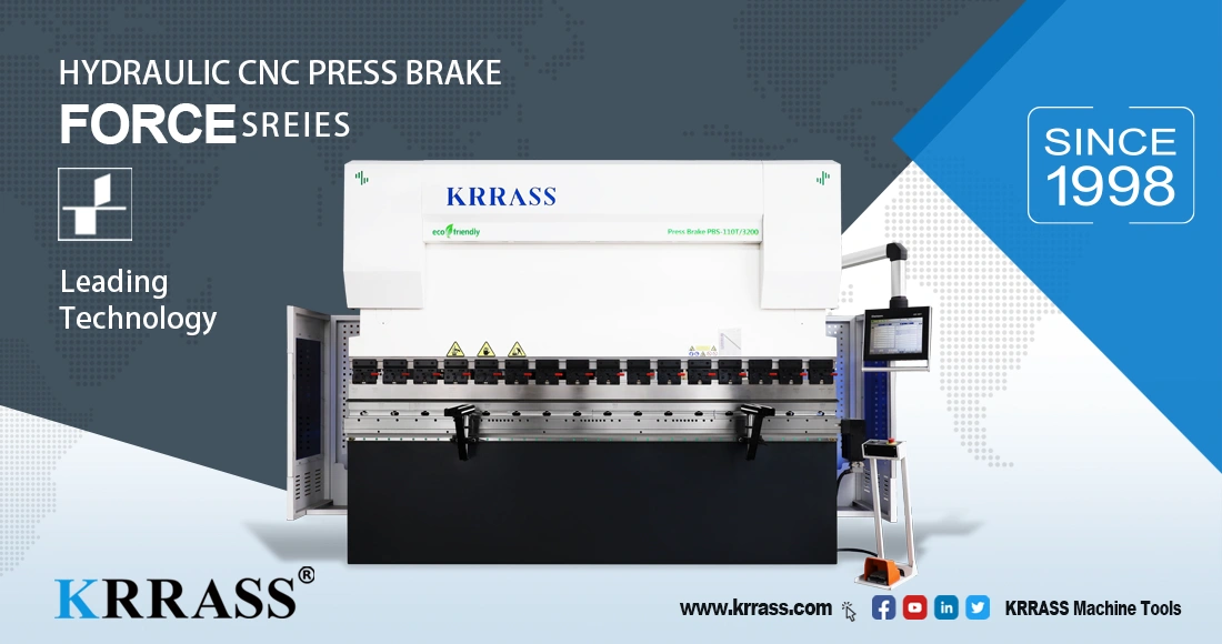
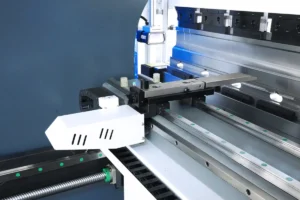
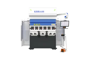
Hydraulic Press Brake has high labor productivity and high working accuracy for bending metal sheets. It adopts different shapes of upper and lower molds, which can be bent into various shapes of workpieces, and the sheet can be bent once by one stroke of the slider. Forming, after many times of bending, a more complex shape can be obtained. When equipped with corresponding equipment, it can also be used for punching. Hydraulic Press Brake body is welded with full-thick steel plates, which has sufficient strength and rigidity.
Press Brake stamping die adjustment:
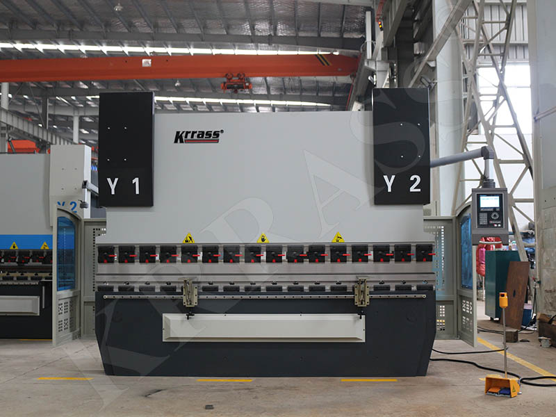
- The mold base adopts the self-made rear mold base of uniform size, and the width of the lower mold plate must be slidingly matched with the width of the "U"-shaped worktable. Play the role of adjusting the mold according to the requirements of the profile.
- The compression spring of the uniform length of the outer shell of the mold base guide column can automatically bounce after punching (mainly to solve the influence of the upper mold of the mold and the upper slider of the Press Brake cannot be connected) upper and lower molds.
- The stamping die of CNC Hydraulic Press Brake is generally based on punching small holes, and the blanking is not good, mainly because the front vertical plate (in the middle of the U-shaped worktable) of the machine tool exists, which is more difficult.
- The material is discharged. Generally, the side and back discharge is used. During the working process, always pay attention to the smooth discharge of the material.
- The pressure plate must be close to but not cover the hole of the upper die guide sleeve. To prevent over-travel from damaging the mold and upper mold from tilting forward, and gnawing on the concave mold and guide post.
- The height of the die must be consistent. That is to say, uniform sharpening of the knife, if it is not uniform, it also needs to be almost leveled with copper and paper. In order to prevent the workpiece from being deformed due to stamping not in the same plane.
- The height of the opening must be consistent and the "T" type pressure plate should always be pressed against the upper template. In order to prevent the mold from suddenly popping up due to the compression spring of the guide pin, the upper mold is pushed out and the upper and lower molds are quickly separated.
- The parts must be made into standard parts to facilitate maintenance and replacement.
- The material hole distance is short, and the mold cannot be installed. It can be made with a multi-hole mold or punched at intervals of the holes.
- The position arrangement on the workbench should not make the slider work when the machine tool is working, that is, the center of gravity of the downward force of the machine tool slider must be consistent with the center of gravity of the punching of the profile hole.
The level adjustment of machine is achieved by adjusting the foot adjustment screw:
- Coarse level adjustment: Place the level on the two raised processing surfaces in the middle of the machine table, use the left and right adjustment screws on the front of the machine to adjust the horizontal level of the machine. The left and right adjustment screws are used to adjust the longitudinal level of the machine tool.
- Accurate horizontal adjustment: After all the electrical parts of the standby bed are connected, recheck the horizontal and vertical level of the machine tool according to the above method. The horizontal and vertical levels are both 1000:0.2mm. After the inspection is passed, the lock nut will be locked. Due to the different softness of the foundation, the level of the machine tool should be rechecked after 30-50 hours of use of the equipment. Note: The adjustment screws of the machine tool must be supported by steel plates before adjustment.
Learn more about our products, please visit and subscribe to our Youtube channel
