Topic: Factors Influencing the Precision of Bend Calculations on a China Press Brake
Question: I am currently utilizing a China press brake that calculates the flat length of material before it undergoes bending. However, it appears that the machine does not adhere to any of the bend allowance formulas I have come across. For instance, when bending 0.67 mm thick sheets with a 12 mm die and a 1 mm radius punch at a 90-degree angle, the machine determines that I need to subtract 1.54 mm from the original material, considering the fact that it is dimensioned on the outside. With our tooling, we should achieve an inside radius of 1.872 mm. Nevertheless, when I input these values into our bend formulas, the resulting bend deduction deviates significantly from the 1.54 mm provided by the machine. I would appreciate some guidance on why the machine seems to employ a different formula than the ones I have encountered.
Answer: We work with both metric and imperial units here in the United States as well. Let's now address the issue you are facing.
First and foremost, I must clarify that without physically being present and working with your specific press brake and its controller, it is challenging to determine the exact reason behind the discrepancies you are observing. Additionally, since I am unaware of your desired inside bend radius, I will assume it to be 1.0 mm (0.039 in.). Furthermore, I will assume that you are bending at a 90-degree angle and utilizing precision-ground tooling for air forming.
Now, why does your machine seem to adopt a different formula compared to the ones you have come across? While it is true that various press brake controllers employ slightly different algorithms, they generally align with the description I am about to provide. These formulas can also be found in Machinery's Handbook in the United States.
There seems to be confusion surrounding the terminology and its application, as well as the related tool selection issues that need to be addressed. These aspects relate to your inquiry regarding the data generated by the press brake controller.
Most controllers base their calculations on certain fundamental parameters, such as correct tool selection. Modern controllers typically utilize air forming as the method for calculations. Therefore, if you are bottom bending, the values returned by the machine will be inaccurate.
Additionally, these programs do not account for potential issues arising from using excessively large or small die openings, or employing punch nose radii that are excessively sharp. Furthermore, there is a possibility that the information produced by the controller is misinterpreted. For instance, is the bend allowance being used instead of the bend deduction value when it should not be?
Bend Functions and Their Applications
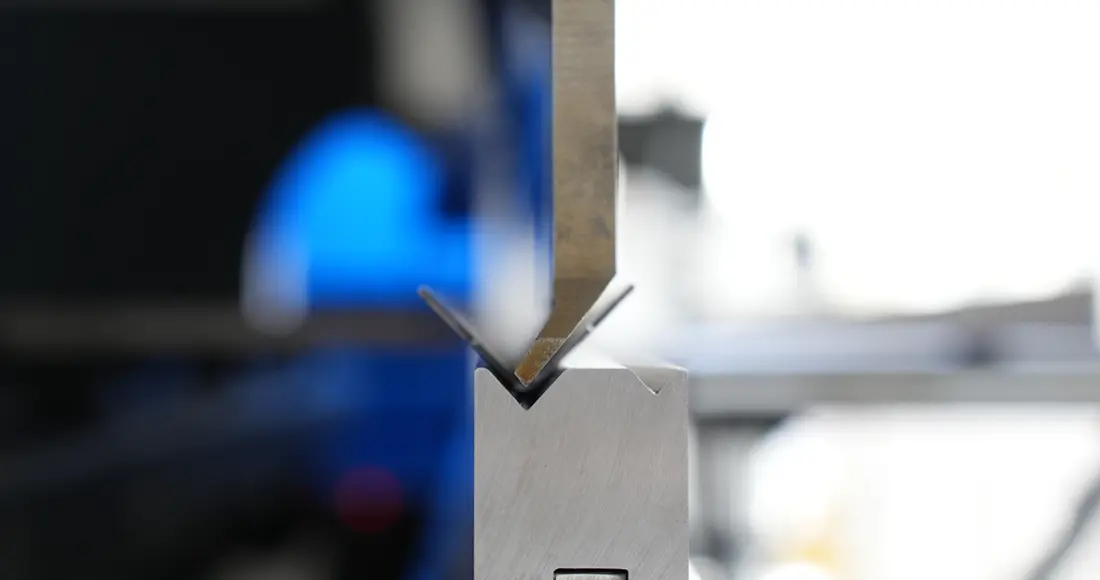
Let's begin by defining the formulas for the three primary bend functions and their applications (refer to Figure 1): outside setback (OSSB), bend allowance (BA), and bend deduction (BD).

The bend allowance (BA) is an added value to the dimensions of the bend, extending from the edge of the part to the tangent point between the flat and the radius. It can be calculated using the following formula:
BA = [(0.017453 × Inside bend radius) + (0.0078 × Material thickness)] × External angle of bend
Note that the value 0.017453 represents pi divided by 180. The value 0.0078 is obtained by multiplying 0.017453 (again, pi divided by 180) by the k-factor, which in this case equals 0.4468. Additionally, the bend angle is always expressed as the outside angle measurement (i.e., the external bend angle in Figure 1).
In your particular application, the BA calculation using imperial measurements would be:
[(0.017453 × 0.039) + (0.0078 × 0.026)] × 90 = 0.0795 in.
Using metric measurements, the same formula yields:
[(0.017453 × 1.0) + (0.0078 × 0.67)] × 90 = 2.0411 mm
It's important to note that when comparing metric and inch values, the calculations yield only slight differences:
0.0795 in. = 1.981 mm
2.0411 mm = 0.080 in.

The outside setback (OSSB) represents the measured distance from the radius and flat tangent point to the apex of the bend:
OSSB = [Tan (Half the bend angle) × (Material thickness + Inside bend radius)]
For your specific application, the OSSB calculation is as follows:
OSSB in inches = [Tan(45)] × (0.026 + 0.039) = 0.065 in.
OSSB in millimeters = [Tan(45)] × (1.00 + 0.67) = 1.67 mm
Finally, the BD can be calculated using the following formula:
BD = (2 × OSSB) - BA
BD in inches = (2 × 0.065) - 0.0795 = 0.051 in.
BD in millimeters = (2 × 1.67) - 2.041 = 1.299 mm
Common Mistakes
Now that we have defined the formulas and calculated some data, let's apply this information to the flat blank. Figure 2 illustrates the differences between the bend allowance (BA) and bend deduction (BD). The BA is added to the total length from the edge to the tangent point of the bend radius (X1 + Y1 + BA), while the BD is subtracted from the total outside dimensions from the edge to the outside of the bend (X + Y - BD).
One common error is subtracting the BA when it should have been added, leading to incorrect flat measurements. Another mistake is utilizing an incorrect bending method in the calculations. For example, if you are bottom bending, the punch nose radius stamps into the material. On the other hand, in air forming, the radius forms as a percentage of the die opening. Employing the wrong forming method will result in incorrect radius values, subsequently affecting the entire calculation.
If you are a regular reader of my column, you are likely aware of the significance of the inside bend radius. It is crucial to accurate sheet metal bending. If the inside bend radius is incorrect, almost nothing else will yield accurate results. Therefore, if you are encountering discrepancies in the calculations, examine the inside bend radius. How are you verifying its correctness? Are you utilizing radius gauges or pin gauges? Moreover, is one tool more reliable than the other?
When bottom bending, it is acceptable to use radius gauges. The punch nose radii are available in standard metric and imperial sizes, and since you are bottoming, the punch radius is stamped into the material.
In air forming, the inside bend radius varies as a percentage of the die opening. Consequently, the inside radius deviates from standard tool increments, making radius gauges impractical. In this case, shop or quality-control pin gauges come into play. These pin gauges are available in 1 mm or 0.001 in. increments, enabling precise checking of any inside radius, regardless of the forming method employed.
Causes of Variation
Upon reviewing your data, I cannot help but question why you are using such a large die opening for such thin material. Assuming you are employing air forming, the inside bend radius should be developed as a percentage of the die opening.
For instance, using A36 steel with an ultimate tensile strength of 60,000 PSI, the inside bend radius should be approximately 16% of the die opening. Therefore, for the 12 mm (0.472 in.) die opening, the inside bend radius should be 1.92 mm (0.075 in.), which is very close to the 1.872 mm (0.073 in.) you calculated.
The machine's calculation of 1.54 mm (0.060 in.) is the correct bend deduction (BD) for an inside bend radius of 1.803 mm (0.071 in.), which is close to the 1.872 mm radius you obtained. However, it is not an exact match. Why is this the case? While slight variations in equations, such as different k-factors, could account for the discrepancies, another potential cause could be material variation.
As I have mentioned numerous times before, no two pieces of material are identical, even if they share the same grade, thickness, yield and tensile strength, and are formed along the same grain direction. Material variation can also impact the "20% rule," named after the air-forming characteristics of stainless steel. This rule is derived from the 16% value I mentioned earlier. However, it is important to note that the rule is not precise and encompasses a range of values. In this example, the A36 material has values ranging from 15% to 17% of the die opening. The variations stem from the differences in the material being formed, and sometimes the range of values can be even wider. Nevertheless, the median value typically proves to be highly accurate.
Moving Towards a Solution
Once again, without physically working with your specific china press brake and its controller, it is challenging to provide a definitive answer regarding the machine's behavior. Nonetheless, I hope that I have provided you with some fundamental background information, demonstrated its application, shed light on potential causes for the observed results, and offered potential corrective measures.
Remember, when facing a problem, perseverance is key. With continued efforts, you will find a solution. Challenges like these often transform into valuable learning experiences.
Request a callback
Visit our product
Visit our Youtube channel
Which press brake machine is right for you?
If you need any questions answered or to discuss your Press Brake requirements for your unique business, please contact us today on 0086 18952087956 or using our online contact form.


