Are you seeking a contemporary alternative to conventional mechanical cutting tools? Fiber laser cutting machines are your best choice! These advanced machines cut various materials with precision and speed using a high-power-density laser beam. Fiber laser cutting technology rapidly replaces traditional metal cutting techniques due to its versatile cutting modes, automatic material savings, and low processing costs. Additionally, the mechanical components of fiber laser cutting machines never come into contact with the workpiece, thus avoiding any injuries that may occur during operation.
Laser cutting is fast, produces smooth cuts, and requires no additional post-processing. You can cut large pieces of material from the entire sheet without needing separate tooling, saving you significant time and money. Fiber laser cutting can handle everything, whether stainless steel, titanium, plastic, wood, or ceramics.
Despite the higher investment in fiber laser cutting equipment, it can be used for precision cutting of various materials with a thickness of less than 12 millimeters.
Therefore, if you need high precision and fast cutting, it's time to consider getting your fiber laser cutting machine!
What is a fiber laser cutting machine?
A fiber laser cutting machine represents a cutting-edge tool for precision cutting. How does it work? Let's understand together.
A fiber laser cutting machine uses a laser beam to cut materials. The laser generator emits the shaft, and the optical path system focuses it into a high-power density laser beam.

As the laser beam interacts with the workpiece's surface, it heats the material to its melting or boiling point, and high-pressure gas blows away the resulting melted or vaporized metal. The fabric can be cut by manipulating the laser beam and adjusting the workpiece's position to achieve the intended cutting outcome.
Fiber laser cutting machines have many advantages as a modern alternative to traditional mechanical cutting tools. They have characteristics such as high precision, fast cutting, unlimited cutting patterns, automatic material savings, smooth cut edges, and low processing costs.
Furthermore, fiber laser cutting machines are continuously improving and replacing traditional metal cutting equipment.
- The mechanical components of the laser cutting machine do not directly contact the workpiece, thereby avoiding scratches during the operation.
- Laser cutting is fast, produces smooth cut edges, and requires no additional processing.
- Laser cutting has a small heat-affected zone, minimizing material deformation and forming narrow slits (0.1mm to 0.3mm).
- Laser cutting does not generate mechanical stress or burrs.
- It offers high processing accuracy and good repeatability and does not damage the material's surface.
- Laser-cutting machines use CNC programming to process any flat shape.
- Large pieces of material can be cut from a whole sheet without tooling, saving time.
Fiber laser cutting machines find extensive applications across diverse industries due to their efficiency, precision, and dependable cutting capabilities.
Working Principle of Laser Cutting Machines

Laser cutting employs a laser beam as the heat source, akin to laser welding, to carry out a thermal cutting process. During the laser cutting process, the temperature of the laser beam exceeds 11,000°C, leading to material vaporization, which plays a crucial role in cutting, apart from melting. Laser cutting is a vaporization process for certain materials, such as carbon and ceramics.
High-power continuous-wave CO2 lasers are the typical choice for metal laser cutting. During the cutting process, operators utilize an inert gas flow to expel the molten metal, achieving a cut that is both smooth and straight. By introducing oxygen flow, the cutting speed can be further improved.
Laser cutting delivers a narrow kerf width, precise dimensions, and a smooth surface finish, resulting in superior cutting quality compared to alternative thermal cutting methods. Lasers can cut a wide range of metallic materials, with thicknesses varying from a few micrometers to 50 millimeters.
Despite the higher investment required, laser cutting equipment is primarily used to cut materials less than 12 millimeters thick precisely. This includes stainless steel, titanium, titanium alloys, refractory metals, and precious metals. Moreover, laser cutting is also employed for cutting non-metallic materials like plastics, wood, fabrics, graphite, and ceramics. For instance, the woodworking industry relies on laser cutting for plywood and particleboard, while the textile industry benefits from its use in cutting fabrics.
Laser cutting also applies in specialized applications such as drilling stone bearings and surgical procedures that utilize lasers as surgical tools. The efficiency and quality level of laser cutting is directly influenced by the laser beam parameters, the performance and precision of the laser cutting machine, and the CNC system's quality.
Components of a Laser Cutting Machine
A numerical control (CNC) laser cutting machine has several main components, including the host, control system, laser source, chiller, and regulator. Each piece has its own separate manual or operating instructions, but here we will provide a detailed description of the host structure and the composition of the electrical control system.
Host Structure
The host of the laser cutting machine is the most crucial part of the cutting process, responsible for achieving cutting precision and functionality.
As the core component of the NC laser cutting machine, the host includes the laser cutting head, cutting worktable, transmission system, and base. The laser cutting head is the output device for the laser beam, precisely focusing it on the workpiece for cutting. The cutting worktable provides a stable platform for placing the material to be missed. The transmission system controls the movement of the laser cutting head on the workpiece, enabling precise cutting operations. The base is the host's supporting structure, ensuring the entire equipment's stability.
Through the coordinated process of the host components, the CNC laser cutting machine can achieve high-precision and high-efficiency cutting operations, widely applied in metal processing, manufacturing, and crafts production, among other fields.
Electrical Control System
The electrical control system plays a critical role in the laser cutting machine, ensuring the versatility of graphic trajectories. It includes the controller, servo, power supply, and sensors.
The controller serves as the central intelligence of the equipment, receiving and processing user input instructions while governing the operation of the laser cutting machine. The numerical control system uses CYPCUT software on the WINDOWS XP platform, ensuring stable and reliable operation. The design incorporates an Ethernet communication interface and a 32-bit microprocessor, enabling fast interpolation computation, user-friendly operation, outstanding dynamic performance, and strong load capacity. The control section of the low-voltage electrical system is housed within the control cabinet, serving as the interface for electrical control. Well-known world brands are used for electrical components to ensure stable operation and responsive performance.
The servo system controls the various moving parts of the host, ensuring cutting precision and stability. The AC servo motors adopted in the servo system drive the laser cutting machine's X-axis gantry and Y-axis slide. They exhibit excellent acceleration performance and rapid response speed, with a maximum positioning speed of up to 50 m/min. The Z-axis of the laser cutting machine serves as the feed axis, driven by an AC servo motor. The Z-axis cutting head exhibits exceptional dynamic response and allows for control via the servo and numerical control.
The power supply system provides the electrical power for the laser source and other electronic devices.
Sensors detect and monitor various parameters during cutting, ensuring accuracy and safety.
Through the coordinated operation of the host structure and electrical control system, the CNC laser cutting machine can achieve high-precision and high-efficiency cutting operations, finding widespread applications in metal processing, manufacturing, and crafts production, among other fields.
Types of Fiber Laser Cutting Machines

If we classify laser-cutting machines based on the laser generator they use, they can be categorized as follows:
- Solid-state laser cutting machines include ruby and YAG laser cutting machines.
- Semiconductor laser cutting machines.
- Liquid laser cutting machines.
- Gas laser cutting machines.
Furthermore, laser-cutting machines can also be classified based on other structural aspects:
CNC laser cutting machines can be classified into different types based on how the cutting head and workbench move about each other. These types include:
- Fixed beam configuration (fixed optical path).
- Beam movement configuration (flying optics).
- Semi-fixed and semi-mobile hybrid design.
A hinged arm fixed optical flying beam transmission configuration is also known as a constant flying path.
In the case of laser cutting machines that use flying optics, only the laser cutting head moves along the X and Y directions, while the workbench remains stationary. The characteristics of this type of laser-cutting machine are as follows:
- It can process large-sized and heavy-weight sheet materials.
- It occupies a small footprint.
- Workpieces can be processed without clamping, facilitating loading and unloading operations.
- This machine offers good acceleration and high positioning accuracy.
As a result, this type of laser-cutting machine is highly regarded as an international mainstream model in the market.
Several typical structures are commonly found in modern laser-cutting machines, including:
- Gantry mobile flying optics structure.
- Beam-progressing flying optics.
- Inverted beam movable flying optics.
- Cantilever portable flying optics structure.
- Robot structure and large-format hybrid flying optics.
- Laser flexible processing system.
Regarding the structure of laser cutting equipment, the machine's frame can be composed of the following:
- Casting structure.
- Welded structure.
- Marble structure.
- The crossbeam can be made from aluminum alloy castings, weldments, or profiles.
Other components are made of engineering plastics, fiberglass, stainless steel, and other materials.
The laser generator required for laser cutting machines should be selected based on the user's processing performance, materials, and dimensional requirements.
Available laser generators include CO2 axial flow lasers, RF slab lasers, vortex lasers, solid-state lasers, and fiber lasers.
Based on the driving mode, they can be categorized as follows:
- The X and Y axes use single-side servo motors with corresponding reducers and high-precision rack transmission.
- The X-axis employs a servo motor with a matching reducer driven by high-precision gears and racks. The presence of two gears helps eliminate backlash.
- They adopt high-precision ball screws directly driven by servo motors. The laser cutting machine employs a disc-type high-inertia engine for direct gear and rack drive.
- Direct drive using linear motors.
CNC laser cutting machines usually have high-precision linear guides and automatic lubrication devices.
One method involves using single-side linear guides with a roller column structure, which is an economical and practical solution.
Another structure is the driving unit that combines the drive and guide rails into one unit, offering easier installation, debugging, and better accuracy, albeit at a slightly higher cost.
Installation and Debugging of Fiber Laser Cutting Machine

The installation and debugging of the laser cutting machine are essential for every factory, so please continue to read the following detailed content before operating:
Shipping List
Unpacking Notes
- Please open the wooden box according to the instructions on the outside of the rigid packaging box to avoid damaging the laser cutting machine equipment inside.
- To prevent any surface scratches or damage to the electrical components, refrain from using sharp objects to remove the protective film.
- Here is the rewritten sentence in English without passive voice: Our company will not replace the cutting machine if it is damaged due to customer reasons.
Content check
- After opening the package, please confirm it is the laser cutting machine you purchased.
- Check if the laser cutting machine has been damaged during transportation.
- Confirm that all parts are present and in good condition through the checklist.
- Contact our company immediately if there are abnormal situations, such as inconsistent laser cutting machine models, missing accessories, damage during transportation, etc.
Installation Environment Requirements
Please refer to the equipment's factory foundation diagram for the installation and fixation of the laser cutting machine. Ensure that the device is transported to a position that can be raised or lowered.
Professional electricians should handle the power distribution wiring according to the requirements, avoiding damaging the machine during installation.
Methods and Instructions for Laser Cutting Machine Debugging
The laser cutting machine's debugging process should be carried out by experienced professionals strictly following the applicable regulations.
Before the debugging process, it is advisable to familiarize yourself with the machine's performance and thoroughly review the provided technical documentation. Accurate debugging is essential for ensuring the machine's proper functioning.
Please don't hesitate to contact us if you require assistance, and we will promptly deliver satisfactory solutions.
Connection of Components in the Distribution Cabinet
Firstly, determine the components as required. After the installation of the features, connect the distribution cabinet as follows:
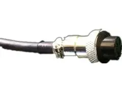
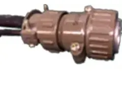
(1) Check if the four connectors on the extended end of the Y-axis were damaged during transportation. The four connectors are load connector, aviation connector, encoder connector, and amplifier connector, as shown in the figure:
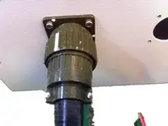
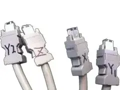
Previous image
Next image
(2) Insert the plugs into their respective positions (each position is unique). Insert the encoder plug into the appropriate servo drive based on the numbering and the amplifier plug into the height adjuster.
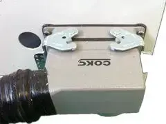
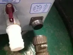
(3) Connect the power cord of the water cooler inside the distribution cabinet to the designated position, as shown in the figure:
Previous image
Next image
(4) Turn on the main power supply. It is a three-phase four-wire system, where the yellow-green wire is the ground wire, and the remaining three are the live wires. With this, the electrical connection of the external circuit is completed. Next, let's look at the connection method of the water cooler.
Caution: Ensure the ground wire of the power cord is securely grounded to prevent interference with internal signals within the cabinet and minimize the risk of electrical leakage.
Connection Method of the Water Cooler
Installation Requirements
Ensure the water cooler is positioned in a stable area, maintaining an adequate distance from the wall. The water cooler's installation position must have sufficient air circulation space to prevent poor refrigeration and excessive temperature inside the distribution cabinet.
Equipment Inspection
Before installation, check the clean water tank for debris and ensure the water is impure-free. Then, inspect the joints of the water pipe system to ensure they are tightened and secure.
Installation Procedure
Follow the markings on the exterior of the water cooler to connect the inlet and outlet water pipes on the water cooler and connect them to the inlet and outlet ports of the laser. Ensure the direction of the water pipes' inlet and outlet ports is aligned correctly. Before joining the water pipes, ensure that there is no debris or foreign objects on the exterior of the water cooler.
Water Quality Standards
Check and close the drain valve, then fill the water tank. The water level should be 30mm to 50mm below the height of the water tank to prevent overflow. The use of tap water for the chilled water cooler is strictly prohibited. Please use high-quality purified water, distilled water, or deionized water. Adding any corrosive liquid is strictly forbidden.
Startup Debugging
An air switch behind the water cooler controls the water pump. After properly connecting the water circuit, please turn on the water pump switch to test its operation. Once the water pump starts, check all joints for any signs of water leakage. If leakage is found, immediately turn off the water pump power, rectify the leak, and then attempt to restart and check the system.
Water Temperature Adjustment
The water temperature is generally 22-24 degrees Celsius in an air-conditioned room. The water temperature in rooms without air conditioning should be 2-5 degrees Celsius lower than the room temperature. If condensation appears on the pipe walls, it indicates that the water cooler's temperature is set too low.
Nozzle and Nozzle Port Laser Adjustment

Nozzle Movement and Adjustment
1) Nozzle
The nozzle's design and the jet's flow conditions directly affect the cutting quality. The manufacturing precision of the nozzle is closely related to the cutting quality.
2) Primary functions of the nozzle:
- Prevent debris and other foreign objects from entering the cutting head and damaging the focusing lens.
- The nozzle can modify the discharge of the cutting gas, controlling the size and area of gas diffusion and influencing the cutting quality.
The following image shows the situation when the nozzle is installed and not installed:

Steps to adjust the laser passing through the nozzle center
In contrast to CO2 laser cutting machines, fiber laser cutting machines do not rely on an optical path and only necessitate laser adjustment at the nozzle.
Apply ink (or transparent tape if not using ink) to the end of the nozzle and affix the white paper to it.
Adjust the laser output power between 30W and 50W, open the mechanical shutter, and quickly switch the electronic shutter once while observing the phenomenon.
Close the mechanical shutter, and remove the white paper, ensuring not to change its relative position.
If there is a significant difference between the nozzle position and the laser center, the paper will not align with the center hole. Since the laser center is fixed, adjust the nozzle center to match the laser center by rotating the adjustment screw on the cutting head handle.
Continue repeating the steps until the laser hole on the white paper aligns precisely with the center of the nozzle, confirming the proper alignment between the laser center and the nozzle center.
As shown in the following image:

The Influence of Nozzle on Cutting Quality and Selection of Nozzle Size
Relationship between Nozzle and Cutting Quality
When the center of the nozzle does not align with the laser center, it has the following impacts on cutting quality:
Cutting Section
Uneven gas distribution occurs when cutting gas is ejected, leading to a stepped appearance on one side of the cut section while the other side remains unaffected. This effect is minor when cutting materials below 3mm but becomes more significant for materials above 3mm, and in some cases, cutting may not be possible.
Sharp Angles
When cutting workpieces with sharp or small angles, localized over-melting can occur, making it challenging to cut thick plates.
Piercing
Piercing becomes unstable and challenging to control, leading to melting during the piercing of thick plates. The stability of piercing conditions is less critical for smaller workpieces.
In summary, the concentricity between the center of the nozzle and the laser is a crucial factor for cutting quality, particularly for thicker workpieces. Therefore, it is necessary to align the center of the nozzle with the laser to achieve better-cutting results.
Note: Nozzle deformation or scaling can have the same impact on cutting quality as mentioned above. Therefore, the nozzle should be handled carefully to avoid deformation, and dirt should be cleaned promptly. The manufacturing precision of the nozzle requires high standards and must follow the correct installation methods. If poor nozzle quality results in changes in cutting conditions, the nozzle should be replaced promptly.
Selection of Nozzle Aperture
The differences in nozzle diameter are shown in the following table:
| Nozzle Aperture | Air Flow | Liquid Melt Removal Capacity |
| Small | Fast | Strong |
| Large | Slow | Weak |
The nozzle diameter options include φ1.0mm, φ1.4mm, φ2.0mm, φ2.5mm, φ3.0mm, as shown in the diagram below:

Currently, the commonly used nozzle diameters are φ1.4mm and φ2.0mm, and their differences are as follows:
For thin sheets below 3mm
- Utilizing a nozzle with a diameter of 4mm will yield a reduced cutting area.
- Opting for a nozzle with a diameter of 2mm will result in a thicker cutting surface and an increased likelihood of molten residue accumulation at corners.
For thick plates above 3mm
- The higher the cutting power, the longer the heat dissipation and cutting time.
- Using a φ1.4mm nozzle may lead to a smaller gas diffusion area, which can cause instability during usage, although it is generally still usable.
- A φ2mm nozzle provides a larger gas diffusion area and slower gas flow, resulting in more stable cutting.
A 2.5mm diameter nozzle is suitable for cutting plates with a thickness greater than 10mm.
In summary, the nozzle size significantly impacts cutting and piercing quality. Laser cutting machines mostly use nozzle apertures of φ1.4mm and φ2mm.
Note: The larger the nozzle aperture, the higher the possibility of sparks and molten splatters damaging the lens and shortening its lifespan.
Beam Focus Adjustment
The cutting quality is significantly influenced by the relationship between the beam focus and the material's surface during the laser cutting process. Correctly adjusting the focus position is crucial. This is usually accomplished by testing and adjusting the focus through cutting. The focus is positioned perfectly when the steel plate exhibits minimal slag and is the smallest size.
If there are changes in the relative position between the cutting head and the plate, the cutting head's and the sensor's zero points must be adjusted. Fine-tuning can be done by changing the cutting height in the software.
When significant adjustments are needed, the position of the sensor and its bracket may need to be adjusted to set the focus correctly.
Exercise caution when performing these adjustments, as mistakes could result in the cutting head hitting the surface and damaging the parts.
Relationship between Beam Focus Position and Cutting Effect
| Name and focus position | Cutting material and section properties |
| Zero focus: focus on the cut surface of the workpiece | Carbon Steel Cutting Instructions |
| Focus on the surface of the cutting bow and arrow, the upper surface is smooth, and the lower surface is not smooth | |
| Positive focal length: focus is on the inner side of the cutting bow | Aluminum Cutting Instructions |
| The focus is in the center, so there is a larger smooth surface, the cutting width is wider than the zero focus, the airflow is larger when cutting, and the perforation time is longer than the zero focus | |
| Negative Focus: The focus is lower than the cutting bow | Stainless Steel Cutting Instructions |
| Stainless steel high-pressure nitrogen cutting, blowing away the slag to protect the cutting section, the cutting width increases with the thickness of the workpiece |
Choosing the Cutting Speed
Choosing the appropriate cutting speed is vital for laser cutting machines and is determined by the material and thickness of the workpiece. The cutting speed plays a crucial role in determining the quality of laser cutting.
Choosing the appropriate cutting speed improves the efficiency of the laser cutting machine and ensures high-quality cutting.
The following are the effects of different cutting speeds on the cutting quality:
Effects of Excessive Cutting Speed on Cutting Quality
- It may result in non-cutting and splattering sparks.
- Some areas may be cut while others may not.
- It leads to an overall increase in the thickness of the cutting section without fusion.
- The excessive cutting speed causes the material to be insufficiently cut, resulting in an inclined cutting section with melted residues at the bottom. Refer to the diagram:

Effects of Insufficient Cutting Speed on Cutting Quality
- It leads to excessive melting and rough cutting sections.
- The width of the kerf increases, causing the entire area to melt into smaller rounded or sharp corners, resulting in poor cutting quality.
- The cutting efficiency could be higher, affecting productivity.
- Observe the cutting sparks to determine the appropriate cutting feed speed: if they spread from top to bottom and slope, the cutting speed is too fast. If the sparks condense without diffusing, the cutting speed is too slow. With the correct cutting speed, the cutting surface will have smoother lines, and the lower part of the material will not fuse. Refer to the diagram:

Selection Guide for Laser Cutting Gas and Pressure
The cutting gas chosen for laser cutting depends on the material being cut, and it plays a crucial role in determining the cutting quality. The selection of cutting gas and the appropriate pressure significantly impact the overall cutting performance and the resulting quality of the cut.
The main functions of cutting gas are to assist combustion and heat dissipation, blow away residues, and prevent them from damaging the focusing mirror in the nozzle.
Influence of Cutting Gas and Pressure on Cutting Quality
- Proper cutting gas helps in combustion and heat dissipation, improving cutting quality.
- Insufficient cutting gas pressure affects the cutting process due to residue accumulation, and the cutting speed may not meet production requirements.
- High cutting gas pressure leads to rough cutting surfaces, wider kerfs, and diminished cutting quality.
Impact of Cutting Gas Pressure on Perforation
- If the pressure is too low, the laser will have difficulty penetrating the cutting plate, leading to prolonged drilling time and reduced productivity.
- Excessive gas pressure causes the melting point to melt and form more prominent molten spots, affecting cutting quality.
- Higher pressure is generally used for sheet metal for laser punching, while lower pressure is suitable for punching thick plates.
- When cutting ordinary carbon steel, the thicker the material, the lower the cutting gas pressure.
- High cutting gas pressure is required when cutting stainless steel, regardless of material thickness.
In summary, the selection of laser-cutting gas and pressure must be adjusted based on specific conditions and requirements for each application.
Most laser-cutting devices are equipped with two gas pipelines: one for oxygen and air and the other for high-pressure nitrogen. Both gas channels are connected to pressure-reducing valves, as shown in the diagram:

Explanation of Pressure Reducing Valves in the diagram: The left gauge indicates the current pressure, while the correct gauge displays the remaining gas capacity.
Warning:
- The nitrogen supply pressure should not exceed 20 Kg.
- The oxygen supply pressure should not exceed 10 Kg to prevent the bursting of the gas pipeline.
The Impact of Laser Cutting Machine Power on Cutting Quality
The cutting quality of a laser cutting machine is influenced by its power. It is crucial to select the appropriate cutting power according to the material and thickness of the workpiece. More than sufficient laser power can lead to poor cutting outcomes.
- Insufficient laser power may lead to the inability to cut through the material.
- Setting the laser power too high can cause excessive melting of the cutting surface, wider kerfs, and inferior cutting quality.
- Insufficient laser power can result in cutting residues and scars on the cutting section.
Therefore, setting the appropriate laser power and suitable cutting gas and pressure will yield excellent cutting quality without forming melt spots.
Maintenance and Troubleshooting of Fiber Laser Cutting Machine
Regular maintenance is required to ensure the laser cutting machine's proper operation. Due to the machine's use of high-precision components, handling them carefully and strictly following the operating procedures during maintenance is crucial. It is also recommended to designate a dedicated person for care to prevent damage to the components.
It is recommended that users keep the following spare parts readily available:
- Acetone (purity of 99.5%, water content below 0.3%, 500ml capacity)
- Degreasing cotton (5 packs, medical-grade or optical-grade)
- Alcohol (500ml, with a purity of 99.5% or higher)
- Dropper (medical-grade)
- Cotton swabs (two packs)
- Multimeter (one)
Installation or Replacement Steps for Cutting Head Internal Lens

(1) Before installing the optical lens, it is essential to wear clean clothing, wash hands with soap or more sanitary, and put on sterile white gloves. Do not touch any part of the lens with bare hands, and handle the lens from the side without directly touching the coated surface.
(2) When assembling the lens, avoid blowing on it with your mouth. Place the lens on a clean tabletop and a few sheets of professional paper underneath.
To ensure proper care of the lens and prevent damage, it is advised to handle it cautiously, avoiding any scratches or accidental drops. To ensure the lens remains in optimal condition, it is essential to exercise caution when taking it to prevent scratches or accidental drops. Avoid exerting pressure on the coated surface of the lens. Before installing the lens, it is advisable to thoroughly clean the lens holder with a clean air gun to eliminate any dust or debris. Subsequently, gently place the lens into the lens holder.
(3) When installing the lens onto the lens holder, avoid applying excessive force when securing the lens, as it may cause deformation and affect the quality of the beam.
(4) Precautions when replacing the optical lens:
- Handle the lens carefully when removing it from the packaging to avoid scratching it.
- Before removing the packaging paper, avoid exerting any pressure on the lens.
- Wear clean gloves when removing the protective and focusing lenses from the packaging, and handle them from the side.
- Avoid dust or other debris falling on the lens when removing the packaging paper.
- Use a clean air gun to blow off dust from the lens, and then place it on an optical lens paper.
- Clean the lens holder and bracket to remove dust and dirt, to prevent foreign objects from falling on the lens during assembly.
- Do not apply excessive force when installing the lens onto the holder to avoid deformation.
- After lens assembly, use a clean air gun to remove dust or foreign objects from the lens.
Cleaning Procedure for Laser Cutting Machine Lens
First, use a clean air gun to blow off the dust from the lens.
Next, employ a clean cotton swab to eliminate any dirt or debris. Dip the cotton swab into fresh, high-quality alcohol or acetone and gently glide it in circular motions, commencing from the center of the lens and gradually progressing toward the outer edges.
Continue performing this procedure until the lens is immaculate, ensuring that you replace the cotton swab with a fresh, clean one after each iteration. Employ a clean cloth to remove any residual traces from the lens, avoiding scratching. Inspect the lens under adequate lighting conditions to assess its reflection quality. A good reflection indicates that the lens is clean. If the review is unsatisfactory, proceed with the cleaning process.
Finally, use the same method to place the cleaned lens into the holder. Do not use the same cotton swab for cleaning again.
Storage of Optical Lenses
- Proper storage of optical lenses is crucial for maintaining their quality.
- It is essential to store the lenses within a temperature range of 10-30°C (50-86°F). Avoid placing the lenses in a freezer or any other environment that can lead to condensation, damaging the lenses.
- The storage environment temperature should not exceed 30°C to avoid affecting the lens surface coating.
- When storing the lenses in a box, they should be placed in a vibration-free environment to prevent lens deformation and maintain performance.
Electrical Inspection
Maintenance primarily involves:
- I was checking the stability of the daily power supply voltage.
- We are keeping the machine's electrical cabinet clean and adequately ventilated.
- We are ensuring the integrity and safety of each electrical component.
Maintenance Cycle
- The maintenance cycles for the laser, water chiller, and air compressor should follow the timetable specified in the user manual.
- The machine should undergo its initial maintenance after 24 hours of operation, followed by a subsequent maintenance session after 100 hours. A comprehensive overhaul should be conducted after six months. After that, regular maintenance should be scheduled every six months or annually, tailored to each customer's specific circumstances and requirements.
Maintenance During Operation
Before operating the machine, it is essential to perform routine checks and maintenance on the laser-cutting device based on the daily inspection checklist. Stop immediately and conduct a thorough inspection if you notice any abnormal sounds during the machine's operation. After using the laser cutting machine, shut it down in the correct sequence and clean the machine table and its surrounding area. Do not leave any unrelated items on the machine table or control panel.
- Regularly check the lubrication pump oil level and refill as necessary to ensure sufficient lubrication of the X-axis and Y-axis rails, maintaining machine accuracy and extending the lifespan of the X-axis and Y-axis rails.
- Clean the Z-axis linear guide and lead screw weekly, removing dust and applying machine oil.
- Check the water and air pipes weekly for any damage and promptly notify company personnel for repairs if any damage is found.
- Clean the air weekly to filter out debris and dust.
- Check the internal cooling water level of the water chiller weekly and refill it if necessary.
- Inspect the contamination of the focusing lens every two weeks and clean it if required to ensure its lifespan.
- Daily inspection of the protective lens to maintain cutting effectiveness.
- Monthly review of the air path to eliminate any potential hazards.
- Regularly check for external cable damage and loose connections in the distribution cabinet wiring interface.
- Adjust the machine's level after six months to ensure cutting precision.
Maintenance During Idle Periods
When the machine is not used for an extended period, apply a protective coating such as machine oil or grease to the moving parts. Wrap them with rust-proof paper and regularly check for rust, removing it promptly and applying rust prevention measures where necessary. (Consider adding a dust cover if the budget allows.) Regularly clean and inspect the machine.
Appendix: Common Troubleshooting Methods
| Problem | Cause | Solution |
| Parts processing without auxiliary gas output | Lack of pressure | Check air pressure |
| Solenoid or wire is broken | Check the solenoid valve or solenoid valve circuit | |
| There is abnormal noise in the shaft movement | No lubricant on moving parts | Add lubricant |
| Check if the motion path is safe | Check that moving parts paths are safe | |
| The cutting head has no laser or the light is weak | No light signal | Check the PWM signal line |
| Laser or fiber is broken | Check if the laser is alarming | |
| Nozzle block, optical path part | Replace the nozzle, adjust the optical path | |
| Crop pattern does not match paper size | Program error | Read the instructions and check for correct operation |
| Positioning accuracy suffers | Check whether the machine accuracy is qualified | |
| Damaged steering gear | Replace or Repair Servos |
The world's top fiber laser cutting machine manufacturers
The leading manufacturers of laser cutting machines worldwide include:
- Germany: Trumpf
- Italy: Prima
- Switzerland: Bystronic
- Japan: Amada, Mazak, NTC
- Australia: HGLaserLab
- China: KRRASS
Note: No "best" choice exists, only a "better" option. Choose what suits you best. Laser cutting is a mature manufacturing process, and the performance of top-tier laser cutting machines is comparable. The selection of a high-quality laser cutting machine mainly depends on the production materials. The following factors need to be considered:
- Cutting width: Typical laser cutting widths range from 0.10mm to 0.20mm.
- Smooth cutting surface: The cut surface should be free of burrs.
- Low thermal deformation: Laser cutting is characterized by thin cuts, high speeds, and concentrated energy, which minimizes heat transfer and reduces deformation.
- Suitable for processing large products: Laser processing does not require molds for manufacturing large products, resulting in lower production costs and improved product quality.
- Laser processing is highly advantageous for new product development as it allows for immediate implementation after the completion of product design, significantly reducing development cycles.
- Material savings: Laser processing utilizes computer programming to cut products into different shapes, maximizing material utilization.
Remember to consider these factors when choosing a laser-cutting machine.
Operation of fiber laser cutting machine
To ensure both machine performance and personal safety, it is crucial to have a comprehensive understanding of the components and operating procedures of a laser cutting machine before utilizing it. Before commencing its use, conduct the following checks:
- Inspect the oil level of the device and, if required, replenish it to keep it within the designated normal range.
- Check for any leaks in the water and air circuits to ensure proper air and water quality without contamination.
- To verify the coaxial alignment of the laser and nozzle, ensure that the laser beam is emitted precisely from the center of the gas nozzle.
- Ensure that the nozzle of the cutting gas is suitable for the cutting process and replace it if necessary.
- Check the connection of the cutting assist gas and adjust the gas pressure to an appropriate level if needed.
Safety precautions and safety signs before and during use
Common signs on fiber laser cutting machines include:

Sign indicating "Caution": Failure to follow proper procedures may result in personal injury or equipment damage.

Sign indicating the presence of a laser beam: Do not pass through the shaft, as it can cause burns or life-threatening injuries.

Sign representing high-voltage power danger: Keep away from high voltage to avoid electric shock or life-threatening situations.
It is essential to be aware of and adhere to these safety precautions and signs when operating a fiber laser cutting machine.
Precautions when using a laser cutting machine
- Avoid direct eye contact with the laser, including the red light.
- Ensure you and any non-work items are positioned away from the laser beam path when the shutter is open.
- Operators must wear protective goggles and stay present during the entire operation of the laser cutting machine.
- If any problems arise during operation, it is crucial to immediately press the emergency stop switch or shut off the main power.
- Regularly monitor the cooling water temperature and working gas pressure while the machine operates.
- Only operate the machine if properly trained and following safety procedures. Unauthorized personnel are strictly prohibited from using the device.
- The laser cutting machine's laser is a Class 4 laser product. The invisible laser beam, lens reflection, and scattered light can harm the human body, especially the eyes. Personnel must take necessary precautions to prevent fire accidents.
- The waste gas generated during laser cutting can injure the operator. Therefore, ensure that the machine's dust extraction function is functioning correctly.
- Keep the laser cutting equipment clean and orderly, lubricate as instructed, and manage tools and accessories properly to avoid loss. If malfunctions occur and the operator cannot resolve the issue, immediately stop the machine and inform the relevant engineers.
- To prevent electric shock damage, only allow professional technicians to inspect or repair the electrical control part of the laser cutting machine.
Sequence for turning on/off a fiber laser cutting machine
The sequence of turning on the machine:
- First, power the control cabinet from the external power supply.
- Ensure the water chiller switch is in the on position (do not turn off the water chiller switch after use).
- Check if the emergency stop switch is in the released position.
- Rotate the key switch to the "on" position.
- Power on the computer.
- Finally, switch on the laser power on the left side.
To turn off the laser cutting machine, reverse the order of these steps.
Software usage and programming
To obtain detailed instructions on utilizing the software, please consult the accompanying manual accompanying the device. The manual contains comprehensive information regarding the specific details that pertain to the software's usage and functionality. You will thoroughly understand how to operate the software effectively by referring to the manual.
Automatic calibration of the height sensor
If the height sensor needs to be calibrated when replacing the nozzle or if the distance of the servo is inaccurate, calibration can correct the height of the follow-up component. Follow these steps:
- Move the cutting head downward to approximately 5mm above the sheet's surface.
- Select "Calibration" → "Floating Head Calibration" → "Confirm" on the height adjustment torch.
- During the process, the cutting head will descend twice, taking about 10 seconds. Check the position of the sheet during this time.
- After calibration, the calibration curve will be displayed on the height adjustment torch. For a typical calibration result, the angle should be smooth. If the calibration result is unsatisfactory, it will affect the cutting effect, and recalibration is required.
Several factors may affect the calibration result, including:
- The unstable surface of the sheet.
- The vibration of the Z-axis slider.
- Severe external electrical interference.
The calibration result is divided into A, B, C, and D categories. The laser cutting machine can be used generally if the calibration result is at "C" or above. If the result is "D," recalibration is necessary to eliminate interference.
Safety of laser cutting machines
Every laser-cutting machine operator must know and adhere to safety measures to ensure their safety.
Safety measures for laser cutting machines
- Appoint a safety administrator to determine their responsibilities and provide training to laser processing operators.
- Define laser safety management areas and post warning signs at the entrances. The symptoms should include information about machine power, laser type, prohibition of unauthorized entry, and the importance of eye protection. They should also include the name of the safety manager.
- Laser processing machine operators must undergo specialized training and can only operate the machine with permission from the safety administrator.
- When the laser processing machine is unused, the key switch must be unplugged and locked to prevent accidental operation and injury.
- Ensure that smoke, dust, and laser working gases generated during manufacturing are exhausted outdoors through an exhaust pipe. The required gas cylinders for machine operation should be stored in an organized and secure manner.
The knowledge that was laser-cutting machine operators should be aware of
- Laser-cutting machine operators must undergo specialized training and reach a certain level of proficiency before operating the machine with the approval of the safety administrator.
- Operators or personnel should wear appropriate laser safety goggles and protective clothing when using or near a laser. Adequate indoor lighting should be provided where protective goggles are required to ensure smooth operation.
- Providing a designated processing area or protective screen is essential to safeguard operators. Additionally, safety devices must be implemented to prevent the scattering of laser beams and ensure the well-being of the operators.
- When opening the processing room door, the laser shutter should be closed.
Safety precautions for laser cutting machines
Laser radiation poses primary risks to the eyes and skin. Laser exposure can cause burns on any part of the body. Therefore, it is essential to avoid placing any part of the body in the laser beam path to prevent accidental injuries.
Protecting the eyes and skin
During laser processing, commonly used lasers include CO2 and YAG lasers, each with different levels of harm to the human body. YAG lasers pose more significant hazards as their wavelength has high transmittance through the human eye, potentially damaging the retina. On the other hand, CO2 lasers primarily cause corneal burns to the eyes. Both types of laser exposure carry risks of cataracts and skin burns. Hence, it is crucial to take appropriate protective measures based on the type of laser being used during the adjustment process.
Fire safety precautions
Laser cutting often involves using oxygen and sparks during the cutting process, increasing the risk of fire. Therefore, the work area should be free of flammable and combustible materials, and necessary protective measures should be in place.
Electrical safety
To minimize the risk of electric shock, you should refrain from touching switches while your hands are wet.
Moreover, operators need to exercise caution around areas of the laser cutting machine designated by illumination signs, as they indicate the presence of high voltage or electrical components. This caution should be extended when approaching these components or performing maintenance tasks. Examples of such areas include protective covers for servo motor locations, junction boxes positioned behind columns, transformer cabinets of the laser-cutting machine, and the doors of electrical cabinets.
Familiarity with functions and buttons
It is essential to thoroughly read the machine manual and electrical schematics to become familiar with the functions and buttons of the laser cutting machine.
Prohibition of unauthorized changes to machine parameters
Do not easily open electrical doors and prohibit unauthorized changes to machine parameters, servo parameters, and potentiometers (matching with the calibration table). If changes are necessary, they must be done after receiving training from the laser cutting equipment manufacturer and obtaining approval from a professional. Remember to record parameter values before making any changes to facilitate restoration to the original state if needed.
Protection against high voltage and X-ray hazards
Laser cutting machines operate at power voltages ranging from several thousand to tens of thousands of volts, so it is essential to prevent exposure to high voltage and X-rays generated by electron tubes under high voltage.
Avoid contact with energized components in electrical cabinets
When the electrical cabinet is energized, do not touch energized components such as CNC devices, servo devices, transformers, fans, etc.
Warning: Wait 5 minutes before touching the terminals after a power outage. After the power is cut off, high voltage may be between the power line terminals. To avoid electric shock, do not touch them immediately.
Fiber Laser Cutting Thickness and Speed Chart
Here is a chart of laser-cutting thicknesses that may be helpful to you:

If you need to choose a Fiber Laser Cutting Machine suitable for you, enter our Fiber Laser Cutting Machine page


