Pagination:
Part.I
Part.II
Part.III
Part.IV
Table of Contents
3 Bending Processing
3.1 Bending Processing Introductions
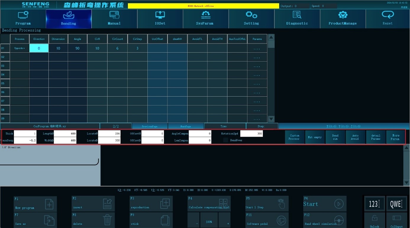
3.1.1 Thickness
Function description: bending material thickness
Parameter setting range: [0.1,2.5]
Default value: 1
3.1.2 Press Depth
Function description: the distance (vector) that the Z axis continues to press down on the surface of the work piece, which is used to compress the work piece when bending. When it is set to 0, the Z axis will stop on the surface of the work piece.
Parameter validity conditions: System Parameters->Common Parameters[612]. It is valid when search depth is set to 0 in torque detection mode.
Parameter setting range: [-3,10]
Default value: System Parameters->Default Parameters [655]. Default value of depression depth.
3.1.3 Length U
Function description: work piece length in U direction.
Parameter setting range: [0,4000]
Default value: 600
3.1.4 Width D
Function description: the width of the work piece in the D direction.
Parameter setting range: [0,4000]
Default value: 600
3.1.5 Locating Point U
Function description: the distance from the outermost edge of the work piece in the U direction to the center of the stopper work piece. (scalar)
Parameter usage conditions: it needs to be set when U direction location is deviated. When the work piece is not deviated, it can be set to 0, and the system will automatically calculate it (positioning point U = work piece length U/2).
Parameter setting range: [0, 3000]
Default value: 0
3.1.6 Locating Point D
Function description: the distance from the leftmost edge of the work piece in the D direction (D1 side) to the center of the pressure rod. (scalar)
Parameter usage conditions: it needs to be set when the D direction location is deviated. When the work piece is not deviated from the center, it can be set to 0, and the system will automatically calculate it (positioning point D = work piece length D/2).
Parameter setting range: [0, 3000]
Default value: 0
3.1.7 Offset U
Function description: the size of the workpiece exceeds the U direction reference plane (guiding rule 3) of the D1 axis positioning block.
Parameter usage conditions: when using positioning mode 0, it needs to be set. When using other positioning methods, the system will automatically generate it based on the input plate size.
Parameter setting range: [-3000, 3000]
Default value: 0
3.1.8 Offset D
Function description: the size of the workpiece exceeds the D direction reference plane (guiding rule 2) of the D1 axis positioning block.
Parameter usage conditions: when using positioning mode 0, it needs to be set. When using other positioning methods, the system will automatically generate it based on the input plate size.
Parameter setting range: [-3000, 3000]
Default value: 0
3.1.9 Angle Compensation
Function description: correct the deviation of the bending angle of the work piece. For example, when the bending angle is set to 90°, if the measured work piece angle is 91°, the angle compensation should be inputted as -1°.
Parameter usage conditions: it is used when the actual angle of the work piece is deviated from the inputted angle.
Parameter scope: valid for all bending steps in the table
Parameter setting range: [-100, 100]
Default value: 0
3.1.10 Length Compensation
Function description: correct the deviation of the bending dimension of the work piece. For example, the bending size is set to 20mm. If the measured work piece size is 19.8mm, the size compensation should be inputted as 0.2.
Parameters using conditions: used when the actual size of the work piece differs from the input size.
Parameter scope: valid for all bending steps in the table
Parameter setting range: [-100, 100]
Default value: 0
3.1.11 Rotation Speed
Function description: rotation speed of C axis.
Parameter setting range: [1, 2000]
Default value: system parameter ->default value [653].
3.1.12 Bend Over
Function description: after selection, the XY axis does not execute the bending action, but the other actions are normal (usually used for manual knife combining setting).
Parameter setting range: select or not select.
Default value: not select.
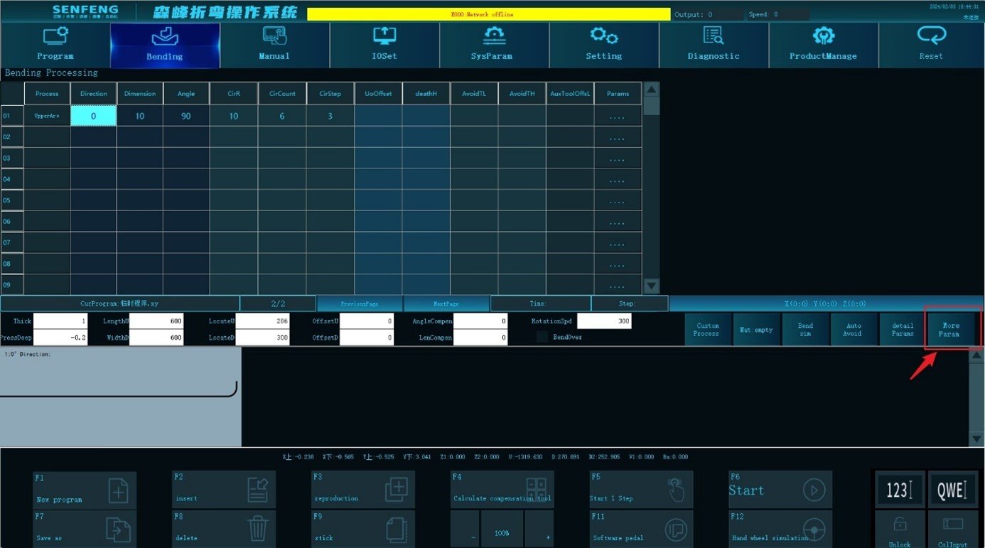
3.2 More Parameters
You can switch to parameter settings such as holding time, bending speed, and rewinding speed through the "More Parameters" key.
3.2.1 Holding Pressure Time
Function description: after performing a bending action, it will stay for a period of time before performing the next action. It is used to reduce the bending rebound amount of the plate and reduce the over-bending angle. 0 means no stop.
Parameter scope: valid for all bending steps in the table.
Parameter setting range: [0, 2000]
Default value: 0
3.2.2 Shif Point
Function description: The position where the speed switches between the normal speed and the pressing speed when the Z-axis rises or falls is called the Shift Point. When multiple bends are performed in the same direction, the Z axis will be raised to the height of the shift point after each bending, and then the U axis will feed the material, at last the Z axis will press down to compress the work piece, and then continue to move down to the next bending. The value entered is the distance from the upper surface of the workpiece to the bottom surface of the upper press tool.
Parameter scope: valid for all bending steps in the table.
Parameter setting range: [0, 100]
Default value: system parameter -> [650] default value of shift point Z.
3.2.3 Bending Speed
Function description: X and Y axis moving speed during bending.
Parameter scope: valid for all bending steps in the table.
Parameter setting range: [1, 2000]
Default value: system parameter -> [651] default value of bending speed.
3.2.4 Fast Moving
Function description: the moving speed of each axis under non-bending conditions.
Parameter scope: valid for all bending steps in the table.
Parameter setting range: [1, 2000]
Default value: system parameter -> [652] default value of fast-moving speed.
3.2.5 Return Speed
Function description: the speed of the U-axis and C-axis when the workpiece returns after the bending is completed.
Parameter scope: valid for all bending steps in the table.
Parameter setting range: [0-2000]
Default value: system parameters->default parameters [666].
3.2.6 Pressing Down Speed
Function description: the speed at which the Z axis presses down from the shifting point to the surface of the work piece.
Parameter scope: valid for all bending steps in the table.
Parameter setting range: [1, 2000]
Default value: system parameter -> [654] default value of pressing down speed.
3.2.7 Positioning Width
Function description: the positioning dimension width in the D direction of the plate during positioning.
Parameter setting range: [0, 3000]
Default value: 0
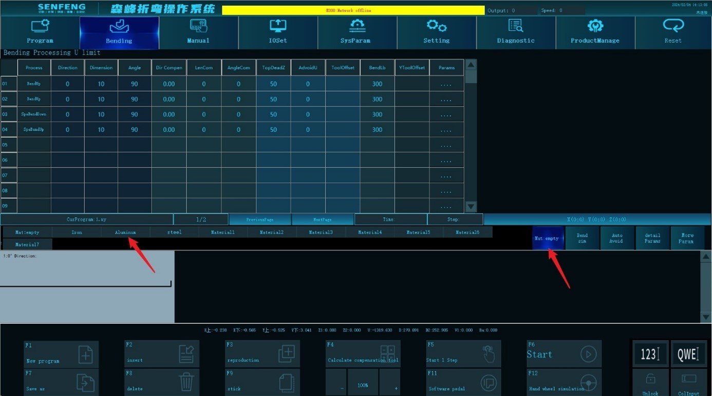
3.3 Material
Click "Material" to select the corresponding bending material and the system calls its bending parameters according to the settings.
Steps:
- Click "Material" to select materials.
- For example: select "aluminum".
3.4 Bending Simulation
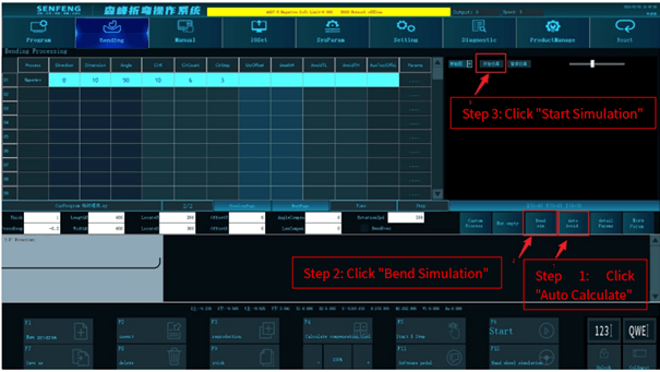
Click the "Bending Simulation" key to generate a simulation.
Steps: after editing the bending program, click Automatic Calculation - Bending Simulation - Start Simulation.
3.5 Description of Bending Process(1)
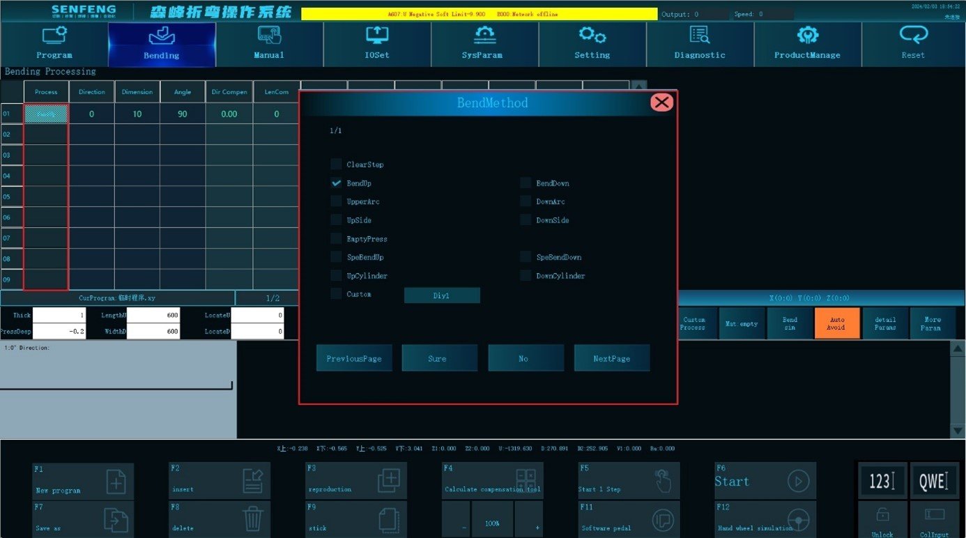
3.5.1 Bend Up
Bend up: Process A1 represents the upper bending.
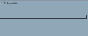
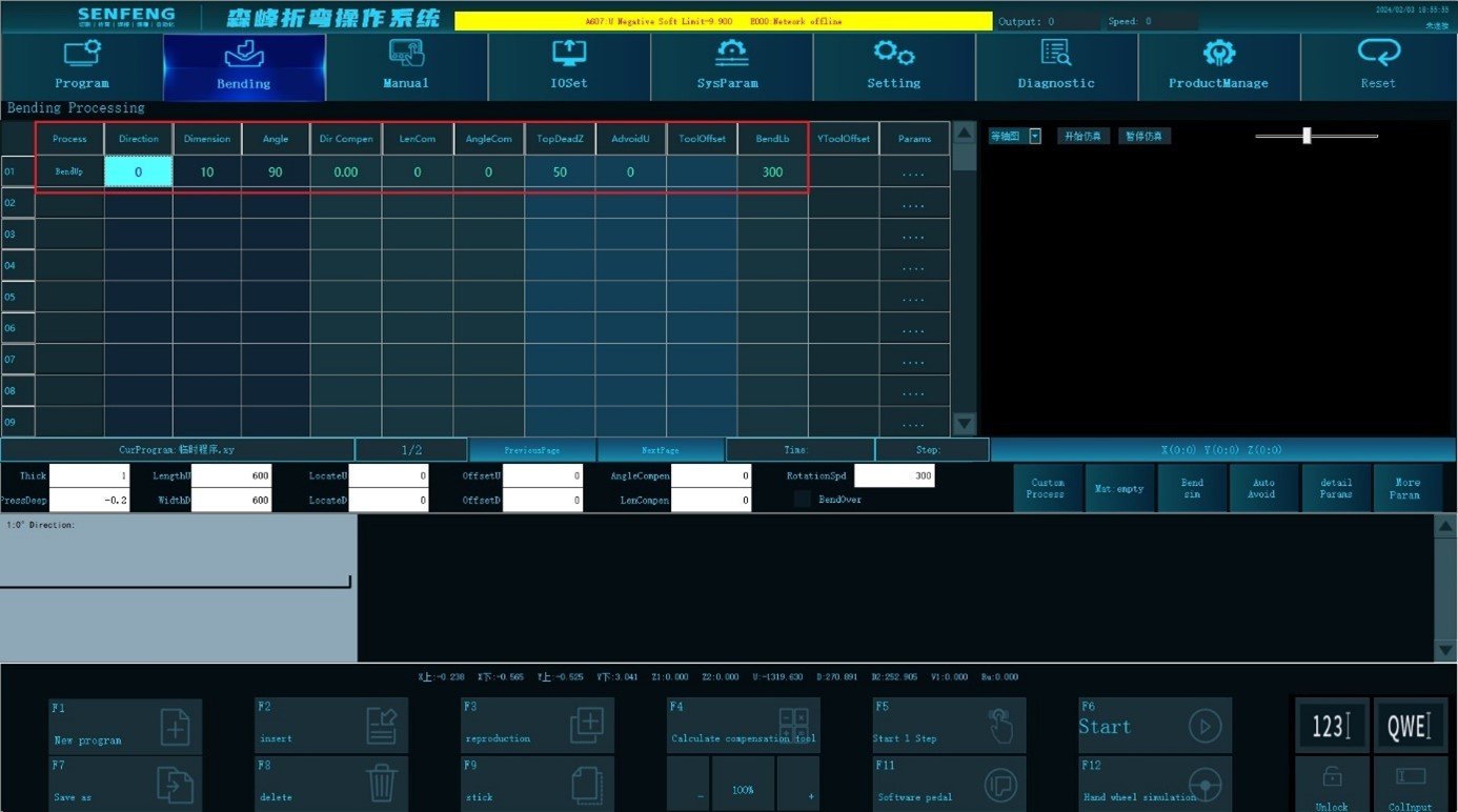
For example: Bend 90 ° in 0 ° direction(fold up with a knife), Dimension 10mm.
Steps:
- Click “Process” to enter the automatic machining interface;
- Select the corresponding process in the "Edit Area": select "A1: Bend Up", Direction "0", Dimension "10mm", Angle "90 degrees";
- The presentation area displays the corresponding graphics;
- After confirmation, click
 “Start”to perform automatic machining.
3.5.2 Bend Down
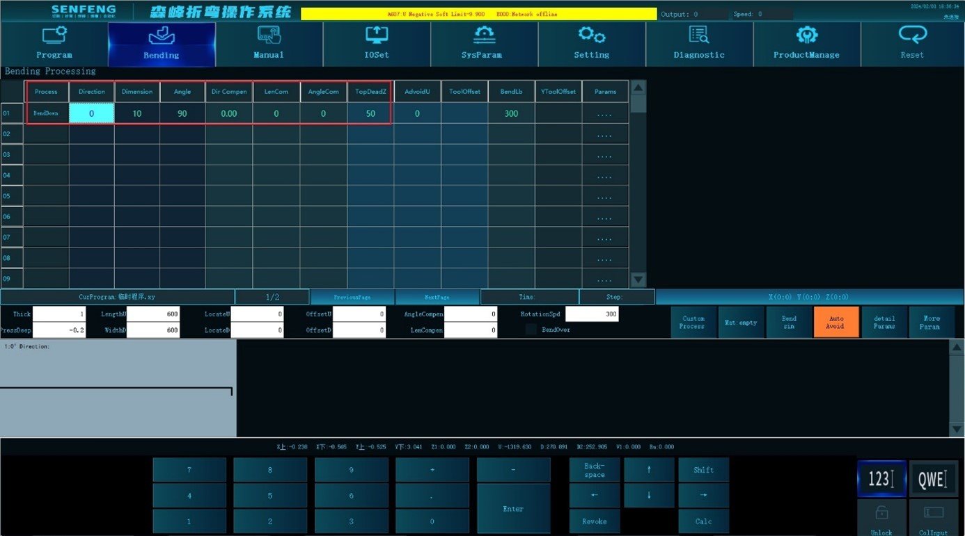
Bend down: Process A2 represents the downward bending.
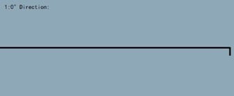
For example: The downward bending is 90 ° in the direction of 0 ° (bend down with the upper knife). Dimension “10mm”.
Steps:
- Click “Process” to enter the automatic machining interface;
- Select the corresponding process in the "Edit Area": select "A2: Bend Down", Direction "0", Dimension "10mm", Angle "90 degrees";
- The presentation area displays the corresponding graphics;
- After confirmation, click
 “Start”to perform automatic machining.
3.5.3 Upper Arc
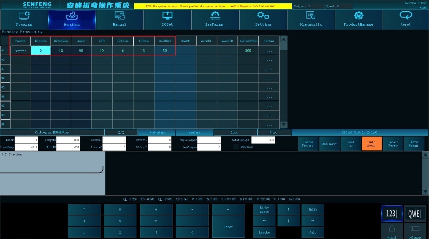
Upper Arc: Process b1 represents the upper arc bending. (The angle is between the plates at both ends of the arc)
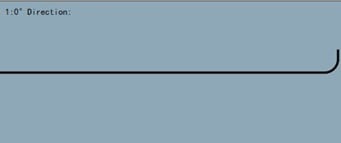
For example: Upper Arc 90 ° in 0 ° direction(bend up with the lower knife), Dimension 10mm, Circular Arc Radius 10mm, Arc Times 6 times, Arc Length Per Bend 3mm.
Steps:
- Click “Process” to enter the automatic machining interface.
- Select the corresponding process in the "Edit Area", select "B1: Upper Arc", Direction "0", Dimension "10", Angle "90", Circular Arc Radius "10", Circular Arc Count "6", (The Arc Step is automatically calculated by the system). Circular Arc Step "3"(The Circular Arc Count is automatically calculated by the system) ;
- The presentation area displays the corresponding graphics;
- After confirmation, click
 “Start”to perform automatic machining.
3.5.4 Down Arc
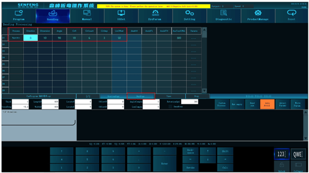
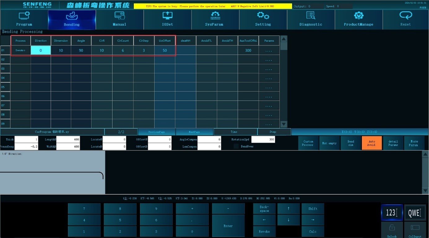
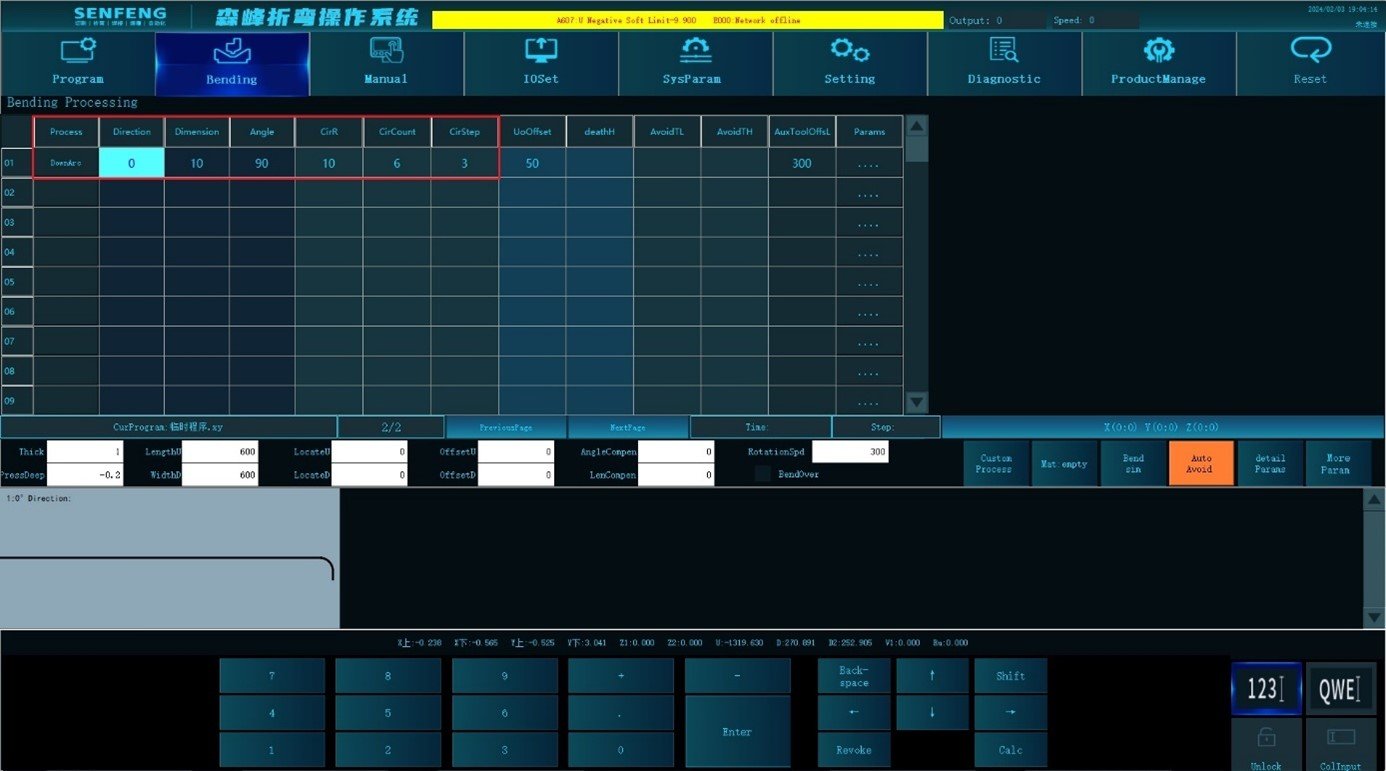
Down Arc: Process B2 represents the down arc bending. (The angle is between the plates at both ends of the arc)
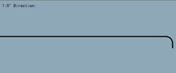
For example: The downward bending 90 ° in the direction of 0 ° (bend down with the upper knife), Dimension is 10mm, Circular Arc Radius "10mm", Arc Times "6 times", Arc Step Per Bend "3mm".
Steps:
- Click “Process” to enter the automatic machining interface.
- Select the corresponding process in the "Edit Area": select "B2: Down Arc", Direction "0", Dimension "10", Angle "90", Circular Arc Radius "10", Circular Arc Count "6" (The Arc Step is automatically calculated by the system). Circular Arc Step "3mm"(The Circular Arc Count is automatically calculated by the system).
- The presentation area displays the corresponding graphics;
- After confirmation, click
 “Start”to perform automatic machining.
3.5.5 Up Side
Upper side: Process C1 means the upper dead edge bending. (Relevant parameters: Death Height)
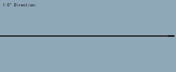
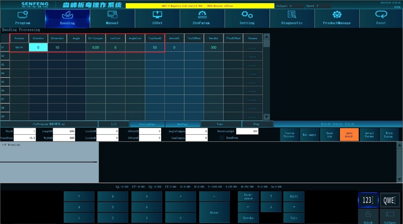
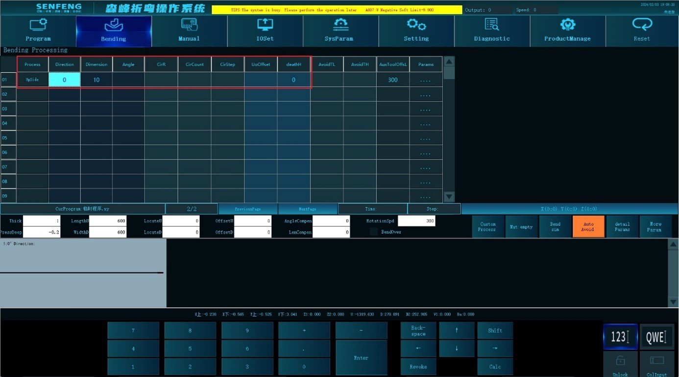
For example: Upper dead edge in 0 ° direction, Dimension 10mm, Death height 0;
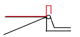
Up side act: After the sheet metal is sent to the bending position, fold the knife up to the minimum angle of the system(System Parameters->Common Parameters【620】). After bypassing the sheet metal and lifting to the top dead center, the Z axis presses down the dead edge.
Death height: The distance between the dead edge and the horizontal plane when the Z axis pressing the dead edge. 0 means direct pressing.
Steps:
- Click “Process” to enter the automatic machining interface.
- Select the corresponding process in the "Edit Area": select "C1: Up Side", Direction "0", Dimension "10", Death Height "0";
- The presentation area displays the corresponding graphics;
- After confirmation, click
 “Start”to perform automatic machining.
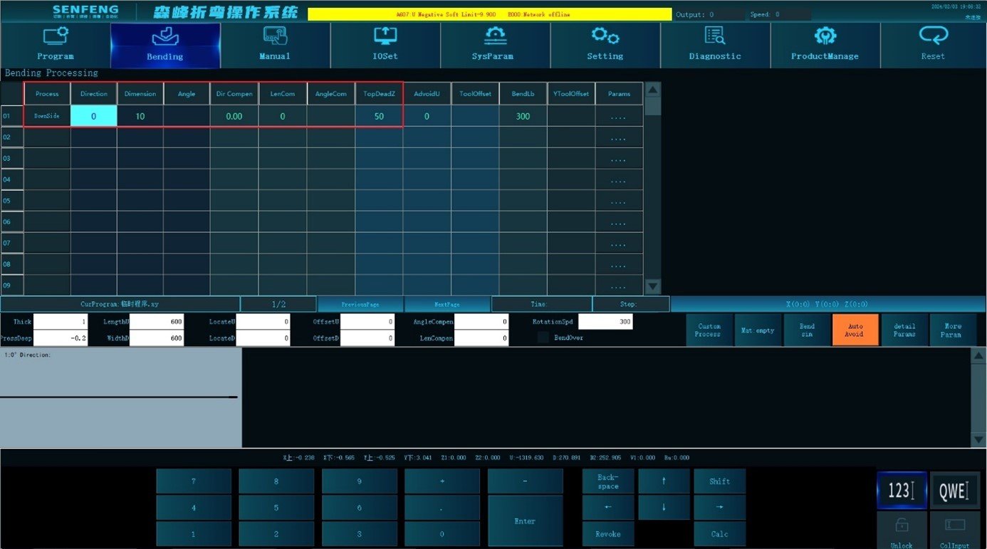
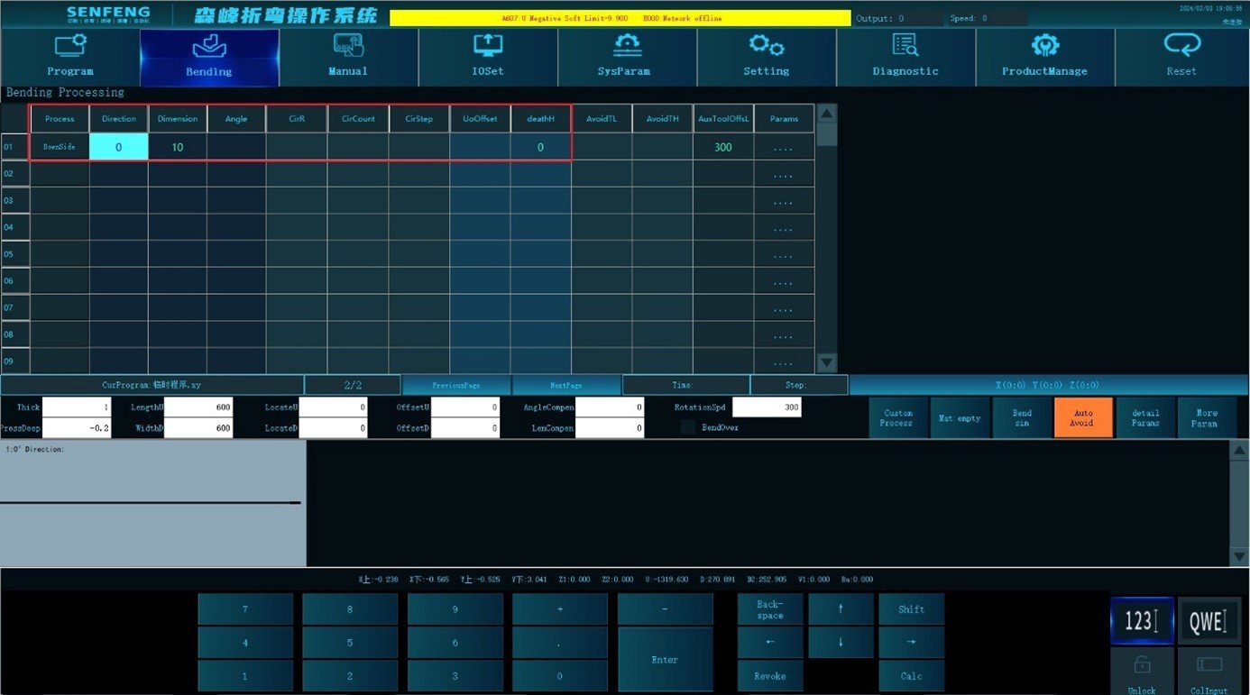
3.5.6 Down Side
Down side: Process C2 represents down dead edge bending. (Relevant parameters: Death Height)
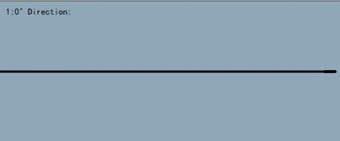
For example: Down dead edge in 0 ° direction, Dimension 10mm, Death Height 0;
Down dead edge act: after the sheet metal is sent to the bending position, the upper knife bends down the minimum angle of the system (System Parameters->Common Parameters【620】). After bypassing the sheet metal and lifting to the top dead center,the Z axis presses down the dead edge.
Death Height: the distance between the dead edge and the horizontal plane when the Z axis pressing the dead edge. 0 means direct pressing.
Steps:
- Click “Process” to enter the automatic machining interface;
- Select the corresponding process in the "Edit Area", select "C2: Down Side", Direction "0", Dimension "10mm", Death Height "0";
- The presentation area displays the corresponding graphics;
- After confirmation, click
 “Start”to perform automatic machining.
3.5.7 Empty Press
Empty press: Process c3 represents empty dead side bending. (Relevant parameters: Death Height)
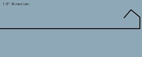
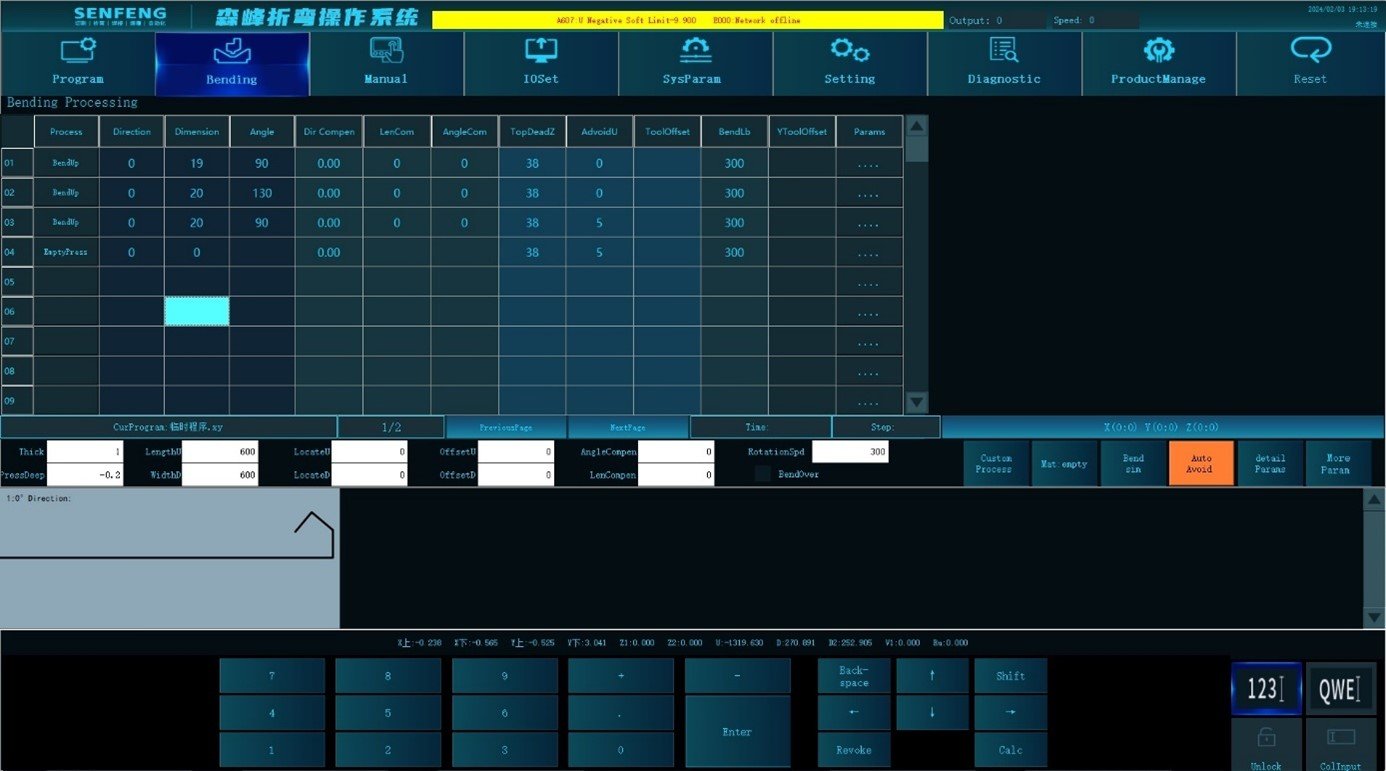
For example: In the 0° direction, first fold up 90°, the bending size is 19mm, then fold up 130°, the bending size is 20mm, then fold up 90°, the bending size is 20mm, and finally perform Empty Side , the Death Height is 18mm;
Steps:
- Click “Process” to enter the automatic machining interface;
- Select the corresponding process in the "Edit Area"
- Step1 of bending: process selection: select Bend Up, Direction "0", Dimension "19", Angle "90".
- Step2 of bending: process selection: select Bend Up, Direction "0", Dimension "20", Angle "130".
- Step3 of bending: process selection: select Bend Up, Direction "0", Dimension "20", Angle "90".
- Step4 of bending process selection: select Empty Side, Direction "0", Death Height "20".
- After confirmation, click
 “Start” and the system will automatically process.
3.5.8 Special Bend Up
Exceptional bend up: Process A3 (Bend the shapes that cannot be processed due to machine interference)
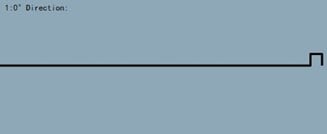
For example: In the 0° direction, first bend down 90°, the bending size is 10mm, then bend down 90°, the bending size is 10mm, and then perform Exceptional Bend Up 90°, the bending size is 10mm.
Steps:
- Click “Process” to enter the automatic machining interface.
- Select the corresponding process in the "Edit Area";
- Step1 of bending:process selection: select the down bending, Direction "0", Dimension "10mm", Angle "90 degrees";
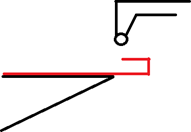
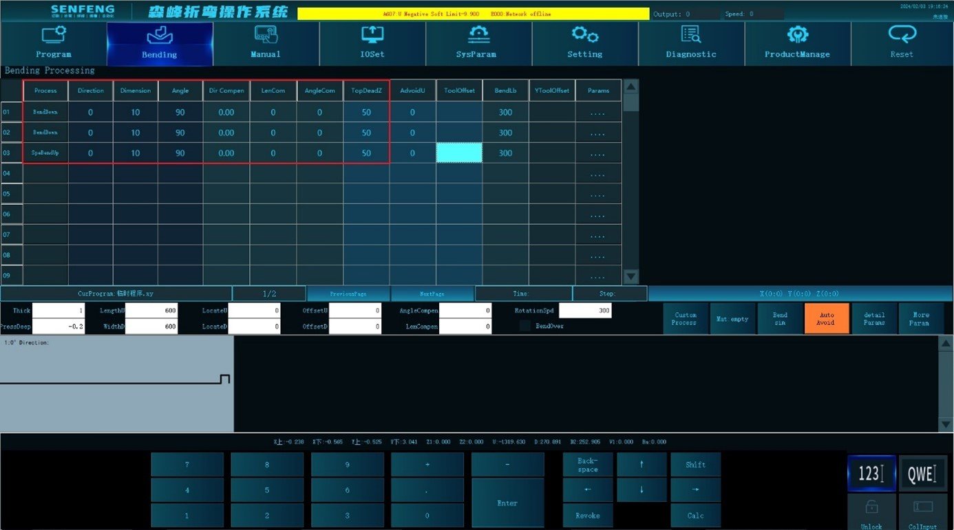
- Step 2 of bending:process selection: select Bend Down, Direction "0" , Dimension "10mm", Angle "90 degrees". The effect of the step 2 of bending is shown in the following figure:

- Step3 of bending: process selection: select Special Bend Up, Direction "0", Dimension "10mm", Angle "90 degrees";
Note: in Step3, when performing upper bending, because the bending size is short and the formed shape interferes with the bending knife, the process need two actions: 1. pre bending (the pre bending angle is set in Detailed parameters->Special bend->Special up bending angle): perform the bending action at the edge of the work piece, and fold the workpiece upward at an angle so that the tool avoids the bending knife. As shown in the following figure:
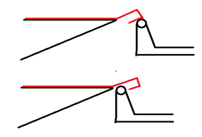
- After pre bending, continue to bend the normal angle. As shown in the following figure:

- The presentation area displays the corresponding graphics;
- After confirmation, click
 “Start”to perform automatic machining.
3.5.9 Special Bend Down
Exceptional Bend Down: Process A4. (Bend the shapes that cannot be processed due to machine interference)
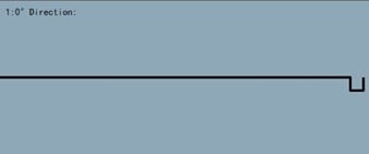
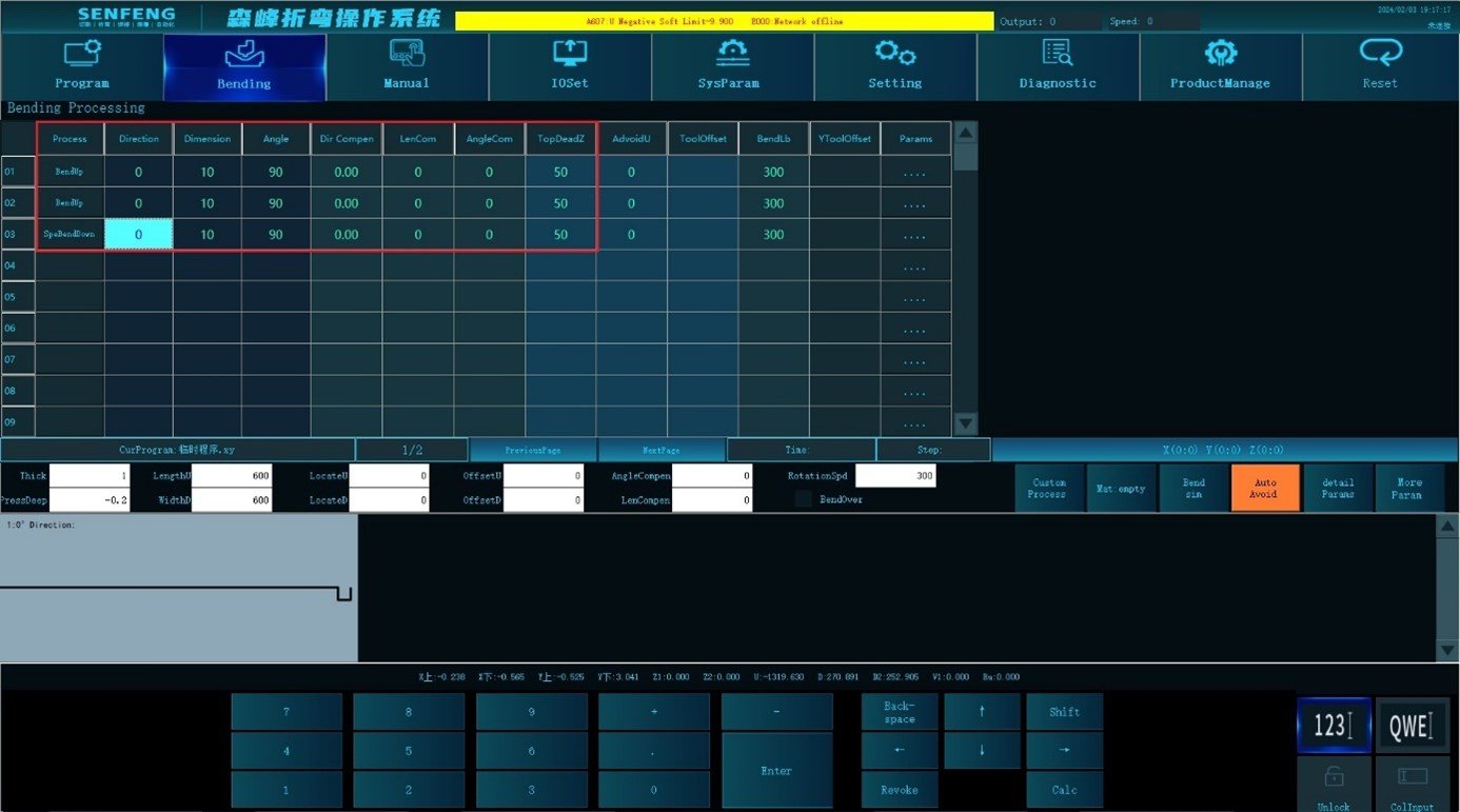
For example: first bend upward 90° in the 0° direction, the bending size is 10mm, then bend upward 90°, the bending size is 10mm, and then perform Special Bend Down 90° and the bending size is 10mm.
Steps:
- Click “Process” to enter the automatic machining interface;
- Select the corresponding process in the "Edit Area";
- Step1 of bending:process selection: select Bend Up, Direction "0", Dimension"10mm", Angle "90 degrees";
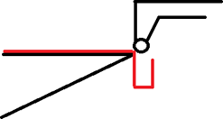
- Step 2 of bending: process selection: select Bend Up, Direction "0", Dimension "10mm", Angle "90 degrees" , the effect is shown in the following figure:

- Step3 of bending: process selection: Exceptional Bend Down, Direction "0", Dimension "10mm", Angle "90 degrees";
Note: when performing downward bending, because the bending size is short and the formed shape interferes with the bending knife, the process need two actions: 1. pre bending(Set it in Detailed Parameters->Special Bend->Special Bend Down Angle): perform the bending action at the edge of the work piece with the bending knife, and fold the work piece down at an angle to avoid the bending knife. As shown in the following figure: 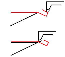
- After completing the pre bending, continue to bend the normal angle. As shown in the following figure:

- The presentation area displays the corresponding graphics;
- After confirmation, click
 “Start”to perform automatic machining.
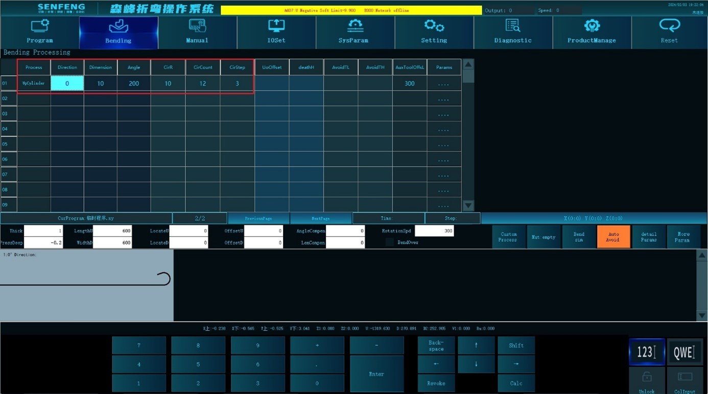
3.5.10 Up Cylinder
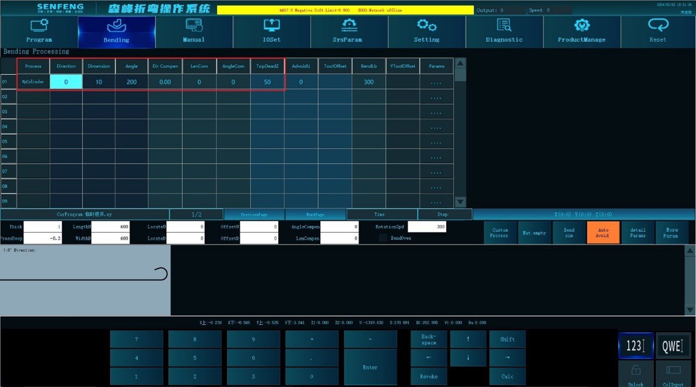
Cylinder Up: Process A5 represents upper cylinder. ( The angle is the central angle)
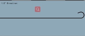
For example: Up Arc 200 ° in the direction of 0 ° (the lower knife is folded up), Dimension 10mm, Circular Arc Radius 10mm, Upper Bending Times 12, Arc Step Per Bend 3mm.
Steps:
- Click “Process” to enter the automatic machining interface;
- Select the corresponding process in the "Edit Area": select "A5: Up Cylinder" for the process, Direction "0", Dimension "10mm", Angle "200", Top Dead Center "50", Circular Arc Radius "10mm", Circular Arc Count "12 times", Circular Arc Step "3mm";
- The presentation area displays the corresponding graphics;
- After confirmation, click
 “Start”to perform automatic machining.
Note: the purpose of this process is to fold an arc with a central angle of more than 180 degrees.
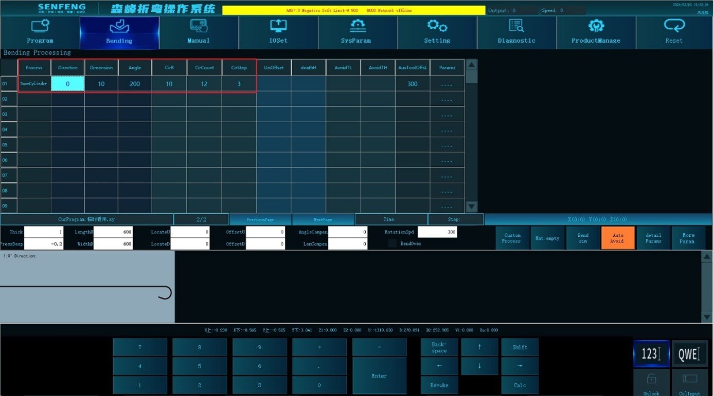
3.5.11 Down Cylinder
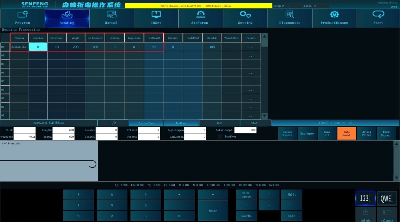
Cylinder Down: Process A6 represents Cylinder Down.( The angle is the central angle)
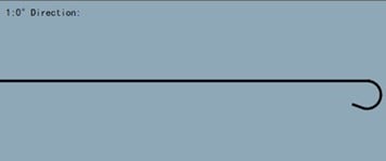
For example: the down arc bending 200 ° in the direction of 0 ° (the upper knife is folded down), Dimension 10mm, Circular Arc Radius 10mm, Count 12 times, Circular Arc Step Per Bend 3mm.
Steps:
- Click “Process” to enter the automatic machining interface;
- Select the corresponding process in the "Edit Area": select "A6: Cylinder Down" for the process, Direction "0", Dimension "10mm", Angle "200", Top Dead Center "50", Circular Arc Radius "10mm", Circular Arc Count "12 times", Circular Arc Step "3mm";
- The presentation area displays the corresponding graphics;
- After confirmation, click
 “Start”to perform automatic machining.
Note: The purpose of this process is to bend a circular arc with a central angle exceeding 180.

