The back gauge of the Press Brake is a key component used to position the plate and ensure the bending dimensional accuracy. It plays a vital role in the plate bending process. The following is a detailed introduction to its function, structural composition, type, working principle, adjustment method and maintenance.
Table of Contents
1.What is the Press Brake backgauge?
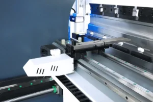
The BackGaugel of the Press Brake is the core component for ensuring the accuracy of sheet metal bending. It is a positioning device installed at the rear of the Press Brake worktable, mainly used to precisely control the position of the workpiece during the bending process, ensuring the accuracy of the bending angle and size. Its performance directly affects the processing quality of the workpiece. The BackGaugel is generally composed of a stop bracket, stop figers, sliders, ball screws, linear guides, synchronous belts, servo motors, etc.
The core function of the BackGauge of a Press Brake is to achieve precise positioning of the workpiece through the coordinated operation of "mechanical structure + drive transmission + numerical control detection". The precision and stability of its components directly affect the quality and efficiency of the bending process. The structural design of different models of Press Brake BackGauges may vary, but the basic principle and key components are similar. High-end models place greater emphasis on automation, intelligence, and precision optimization.
Many customers, when purchasing a Press Brake, do not know how to properly select the type of BackGauge, nor can they distinguish the differences among the common 4+1 axis, 6+1 axis, and 8+1 axis. So, what are the differences between them? Don't worry. Let me teach you how to choose the type of BackGauge so that you can achieve the production efficiency and product quality you desire.

4+1 Axis BackGauge

6+1 Axis Backgauge

8+1 Axis Backgauge
2. What are the axes of the BackGauge of the Press Brake?
The common BackGauge of the Press Brake are divided into X-axis (X1, X2), R-axis (R1, X2) and Z-axis (Z1, Z2). Their movement methods are slightly different. The X-axis usually controls the left-right movement of the BackGauge, the R-axis controls the up-down movement, and the Z-axis controls the left-right movement of the stop fingers.
These three axes work together during the bending process to jointly control the position and posture of the BackGauge, thereby achieving precise bending of the metal sheet. The numerical control system can realize various complex bending operations by precisely controlling the movements of these axes, meeting the needs of different metal processing.
Now, let's proceed to explain based on the movement directions and functions of these axes.
Press Brake X-axis:
Movement direction: The X-axis is mainly responsible for the front-back movement of the backing plate after the Press Brake is operated on the worktable surface, to determine the front-back position of the metal plate during the bending process. The movement range of the X-axis is fixed, but it can be divided into X1-axis and X2-axis to achieve more precise positioning.
Function: By moving the X-axis, the position of the metal plate in the bending die can be adjusted, thereby controlling the angle and shape of the bending.
Press Brake R-axis:
Movement direction: The R-axis mainly controls the up-and-down movement of the BackGauge stop finger, that is, the vertical position of the BackGauge stop finger.
Function: The movement of the R-axis can adjust the height of the BackGauge, enabling them to adapt to different thicknesses of metal plates or achieve different heights of positioning during the bending process. The movement of the R-axis also needs to work in conjunction with the X-axis and Z-axis to ensure the precise position and angle of the metal plate during the bending process.
Press Brake Z-axis:
Movement direction: The Z-axis mainly controls the left-right movement of the BackGauge, that is, the lateral position of the BackGauge.
Function: The movement of the Z-axis enables the independent positioning of the BackGauge stopper, thus adapting to different shapes and sizes of metal plates. The Z1 and Z2 axes can respectively control the stop fingers on both sides of the BackGauge, achieving more flexible positioning and bending.
3. How to select the configuration of the BackGauge for the Press Brake?
1) If the product mainly adopts "right angle / simple angle bending" (such as shelves, distribution cabinets): choose 4+1 axis, which offers high cost-effectiveness.
2) If it involves "conical shapes, twisted surfaces" (such as irregular pipes, automotive interior parts): choose 6+1 axis, focusing on balance accuracy and cost.
3) If producing "ultra-precise curved parts" (such as aviation sheet metal, medical equipment): must be 8+1 axis, and it is necessary to be equipped with high-precision detection equipment (such as laser trackers).
The fundamental differences among 4+1 axis, 6+1 axis, and 8+1 axis lie in the upgrade of "multi-dimensional control capability" - the more axes there are, the more precise the equipment can control the workpiece posture and mold compensation, but the cost and technical threshold also increase. Enterprises need to select the appropriate axis configuration based on product precision requirements, production batch size, and budget to avoid problems such as "overconfiguration" or "insufficient capability".