Fiber Laser cutting machine software is a special software used to control the operation of laser cutting machines, plan cutting paths and achieve precise processing. It supports the import of common design file formats (such as CAD, AI, DXF, SVG, etc.), or directly draw graphics (straight lines, curves, polygons, etc.) in the software, convert the design graphics into the motion trajectory of the laser head (ie “tool path”), optimize the cutting sequence (such as from inside to outside, avoid repeated paths), reduce material waste and processing time. It is a bridge connecting design creativity and hardware equipment, and is widely used in metal processing, advertising production, woodworking engraving, electronic component cutting and other fields.
Table of Contents
1.Open the software without a control card
- Re-clean the pins of the control card and plug them in.
- Re-install the software.
- Re-install the computer system.
2.The 8000 system cannot scan the BLT cutting head
- Check whether the connection between BCS210E height controller and BLT cutting head is normal.
- Unplug the PWE network cable connecting BCS210E and cutting head, check whether the pins at both ends of the cable are bent, deformed or broken, and check whether the PWE network cable has a large angle bend.
- Reconnect the PWE network cable to BCS210E and cutting head, power on and start the software normally, check whether the green light and link light of BCS210E network port are normal
- If there are no problems, please contact Bochu
3.The bus system alarm fails to find the slave station and the data reception times out.
- Scan in the platform configuration to see if it can be scanned. After the scan is successful, you need to add
- If it cannot be scanned, you need to check the hardware, see if the expansion card is powered normally, and see if the network port is connected normally. If the yellow light of the network port is on and the green light flashes, it is a normal connection. If the flashing is abnormal, there is a problem with the hardware device, the network cable or the communication module of the network card or expansion card is abnormal. Need to be replaced for troubleshooting
4.The system enters demonstration mode
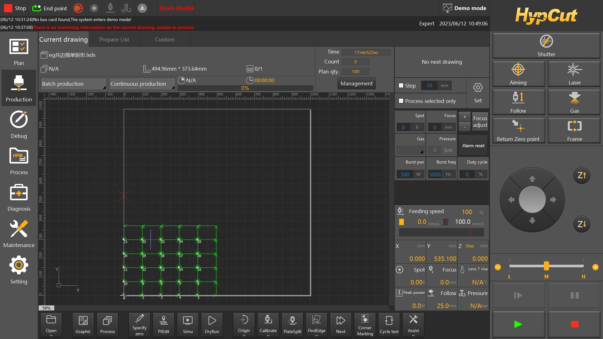
- Open the system software, about, observe whether the confidentiality has expired, the encryption has expired, contact the business to decrypt,
- If the serial number is not displayed, reinstall the software, and check whether the software driver has been installed successfully.
- Turn on the computer, clean the internal dust, and when you open the software, the pop-up window does not detect the motion control card. The system will run in demonstration mode. Return to the desktop, right-click My Computer, open the Device Manager, and check whether the computer recognizes the motion control card.
- You can find PCI devices with exclamation marks: exclamation marks indicate that the driver is not installed properly. If it is a newly installed Windows system, please use Driver Genius or other driver detection tools to detect whether the computer driver is installed normally. If the device in normal use suddenly has a problem, please try to reinstall the software and check the driver installation.
- You can find the Bochu motion control card with an exclamation mark, which means that the driver installation is abnormal. Right-click to uninstall the driver. If it is a 1204/1205 motion control card, please download and install the 658.10 version of CypCut software. For other boards, please download the latest version of CypCut software
5.Reminder Etherercat: Data reception timeout alarm
- Generally, when adding an expansion card (1000 system plus 4516/4508 board for automatic focusing; 2000 system with integrated board and tube, plus 4516/4508 board), the machine suddenly loses power, the network cable is disconnected, the data connection times out, the machine is restarted and powered on, the software is restarted, and generally the problem is solved; if the network data frame length error occurs during cutting, the network cable is too long, the interference is serious, replace the short network cable, restart the machine and power on, restart the software, and generally the problem is solved
6.The limit signal is unreliable and the limit is always effective
- Find the corresponding limit position where the software reports an error, remove the limit, and test whether the limit is normal with metal materials without being disturbed by the installation position. If the limit light is on or off when close to the metal, it is judged that the limit function is normal. If the limit installation position is too close to the sheet metal, it is judged that the false alarm is caused, and the limit locking nut distance is readjusted.
- The limit does not respond when close to the metal. It is necessary to check whether the power supply of the limit is normal. Generally, the brown wire is connected to 24V, the blue wire is connected to 0v, and the black wire is connected to the signal wire. First, measure whether the voltage of the brown and blue wires is 24V. If the voltage is normal, the limit is damaged and the limit is replaced; if there is no voltage, check the power supply line problem;
- The limit power supply is normal, the function is normal, and the system still alarms. At this time, it is necessary to turn on the motion control card monitoring or the terminal board indicator light to check whether the signal is fed back to the control card. If the indicator light does not change, it is necessary to check whether the high and low levels are wired correctly and whether the signal line is broken.
7.There is no alarm in the alarm driver of a certain axis of Bochu software
- Replace the two-axis drive to the board pulse communication line, restart the software to see if there is an alarm
- Check the drive parameters
- Clean the computer board slot
- Update the software
- Reinstall the system
- Test the continuity of the 62-core communication line
8.The full-stroke three-chuck returns to the origin prompting that the height adjuster is not in the docking position and the y3 coordinate has a conflict
- Problem: The full-stroke three-chuck return to origin prompts that the height adjuster is not in the docking position, and the Y3 coordinate conflicts with the inner side of the cutting head. Alarm: The height adjuster is not in the docking position.
- Alarm reason: It is detected that the Z axis and X axis are not in the docking position, and the Y3 coordinate is greater than the processing position coordinate. There is a risk of hitting the cutting head. The Y3 coordinate cannot continue to increase to protect the cutting head. When Y3 returns to the origin, the coordinate is greater than the processing position coordinate and an alarm is issued. First execute Y3 negative jog to make the alarm disappear, then the X-axis height adjuster returns to the origin first, and then the Y axis returns to the origin
9.The full-stroke three-chuck returns to the origin prompting that the height adjuster is not in the docking position and the y3 coordinate has a conflict
- In laser tube cutting machines with multiple longitudinal follow-up brackets, the height of the follow-up brackets is often different due to the different installation heights of the bracket axis sensors. Because the bracket follow-up in TubePro will make the lifting brackets rise to the same height, it is necessary to modify the retraction distance of each axis to make them reach the same height. The operation is as follows:
- Move the brackets to the same height.
- Set up standard pipes on adjacent brackets and place a level on the pipe.
- Step each bracket to make the pipe level.
- Record and add or subtract to the retraction distance of the bracket axis accordingly (modify in the platform configuration tool → general axis).
- All brackets return to the origin
- In particular, for a mechanism with automatic loading, the bracket closest to the middle clamp may be slightly lower than other brackets to prevent the pipe from falling during the loading process and causing the pipe to collide with the bracket.
10.The seven-axis pulling prompts that the pipe is too short and the remaining tailings cannot be processed
- When cutting with three chucks or two chucks, the system will judge that the remaining length of the pipe in the mechanical coordinates is less than the length of the CAD drawing, and a pop-up window “The given motion command has exceeded the travel range!” or the following log prompt will pop up, causing the processing to be suspended.
- Automatic avoidance error: 3000.00 parts are left uncut, and there are only 2686.00 remaining pipes. The Y maximum value of the tail part cannot be cut 8894.00, which is greater than the positive stroke of the Y1 axis 8800.00. The length of the cuttable part = the positive stroke of the Y axis – the current coordinate of the Y axis. In particular, after enabling avoidance: the length of the cuttable part = the positive stroke of the Y axis after avoidance – the current coordinate of the Y axis.
- Please confirm whether ① the stepping distance is correct and ② the positive stroke of the Y axis is set reasonably. Or when the difference between the part length and the remaining pipe length is small, appropriately adjust the clamping position of the main clamping claw (the tail of the pipe does not extend to the deepest part of the claw) to achieve the cutting purpose.
11.Fiber Laser Cutting Automated linkage equipment, the main body and auxiliary are separated, and the feeding effect is unstable
- Kaiping equipment such as rolling, automatic material rack feeding and chuck feeding, etc. need to be well aligned and concentric. Although there are auxiliary guides, the alignment must meet the standards. For example, when Kaiping equipment is installed abroad, the offset at the end of the alignment of equipment of more than 10 meters must be within 4mm. In addition, the horizontal level must be on the same plane, and the foundation must be built in advance to draw the center line. For example, the center of the rack and chuck of the single-axis material pulling must be precisely concentric.
12.Remind that Y+-, X+-, Z upper and lower limits are effective, X, Y, Z, 4-axis servo, alarm
- Check whether the emergency stop is turned on, both in front and behind the exchange station, and whether the switch power is turned on.
- At the same time, an alarm appears, the system control card is not powered on, measure the 24V power input, if it is lower than 24v, adjust the power box potentiometer, if there is no effect, replace the power box
13.Flying cutting, missing graphics, inaccurate cutting size
- Open the control card monitoring, X, Y axis sends pulses, check the feedback pulses, if the direction is opposite, open the software, change the axis pulse reverse direction, solve
- Cut a straight line 1000mm., measure the actual size, actual size * current movement / software set size 1000, get the new movement, software platform configuration change movement.
- As the focus changes, the slit becomes larger, set compensation,
- Diagonal deviation, 1-2mm, platform configuration, change vertical correction, deviation is too large, check the slider, whether the screw is loose, loosen the Y-axis slider screw at the other end, reducer, modify the Y-axis servo direction, same direction, fine-tune the beam, and then modify the Y-axis direction in reverse, solve
14.Positive and negative limit alarm after sudden power failure
- After a sudden power outage, there is a probability that the background configuration file will be lost. Reconfigure the background parameters.
- Check whether the sensor switch signal is normal
15.During the cutting process, the cutting head is constantly lifted up
- Calibration problem: After replacing the nozzle, the floating head capacitance was not recalibrated.
- Laser scattering on the nozzle, or abnormal blowing, etc., caused the nozzle temperature to rise abnormally (above 100°C), changing the body capacitance of the cutting head
16.Fiber laser cutting system Bochu 8OOO system watchdog alarm
- The network is disturbed and needs to be reconnected to the ground wire.
17.No action when walking on the border
- Check if the drawing size exceeds the stroke
- Check if other drawings interfere and cause the stroke to exceed the range
- Create a new interface, import the drawing and check to process only the selected graphics, or change the stop point:
18.No action when walking on the border
- Check the docking point settings
- Check whether the edge search positioning point exceeds the travel range
- Check whether the platform configuration settings are checked for fast edge search or special edge search
- The capacitance value changes greatly and there is interference
- Contact the Bochu manufacturer
19.After power on, the Z axis moves in one direction
- Check whether the mechanical parameters are set correctly
- Check whether the lead screw pitch is set correctly
- Check whether the pulse number and driver parameters are correct
- Check whether the servo line connection is reliable and re-plug the servo line
20.Obvious pause during processing
- Check the cutting process dwell time and whether to add cooling points
- Check the global parameters for air opening delay and first point air opening delay
- Check the PLC process analysis problem
- Wait for the focus to be in place and check the positioning speed and acceleration of the cutting head in the background configuration
