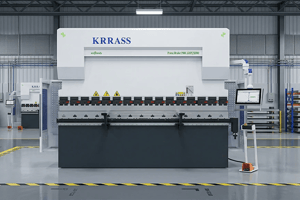
Press Brake is a professional mechanical equipment used to bend metal sheets (such as steel sheets, aluminum sheets, etc.), and is widely used in sheet metal processing, machinery manufacturing, automobiles, home appliances, steel structures and other industries. It bends straight sheets into specific angles or shapes (such as right angles, arcs, U-shaped, V-shaped, etc.) according to design requirements by applying pressure, and is a key equipment for realizing sheet metal parts forming.
Whether it is a hydraulic Press Brake, a mechanical Press Brake, a manual Press Brake, a pure electric Press Brake, a CNC Press Brake, or a regular Press Brake, each type of Press Brake has the same mission: to process metal with unparalleled precision. This precision ensures that every bend meets your exact specifications, which is essential to ensuring the quality and efficiency of your project.
In this article, we will focus on the main components that make the Press Brake so effective, discuss common types, and provide practical tips for troubleshooting and maintenance to keep your machine in top condition.
Table of Contents
1.What is a Press Brake? How does it work?
Press Brake is a machine that can bend thin plates. Its structure mainly includes a bracket, a workbench and a clamping plate. The workbench is placed on the bracket. The workbench consists of a base and a press plate. The base is connected to the clamping plate through a hinge. The base consists of a base shell, a coil and a cover plate. The coil is placed in the depression of the base shell, and the top of the depression is covered with a cover plate. When in use, the coil is energized by a wire, and after energization, an attractive force is generated on the press plate, thereby clamping the thin plate between the press plate and the base. Due to the use of electromagnetic force clamping, the press plate can be made into a variety of workpiece requirements, and can process workpieces with side walls, and the operation is also very simple.
Press Brake is divided into manual Press Brake, hydraulic Press Brake, CNC Press Brake and pure electric Press Brake. Manual Press Brake is further divided into mechanical manual Press Brake and electric manual Press Brake. Hydraulic Press Brake can be divided into torsion shaft synchronization, mechanical-hydraulic synchronization, and electro-hydraulic synchronization according to the synchronization method. Hydraulic Press Brake can be divided into upper and lower types according to the movement mode.
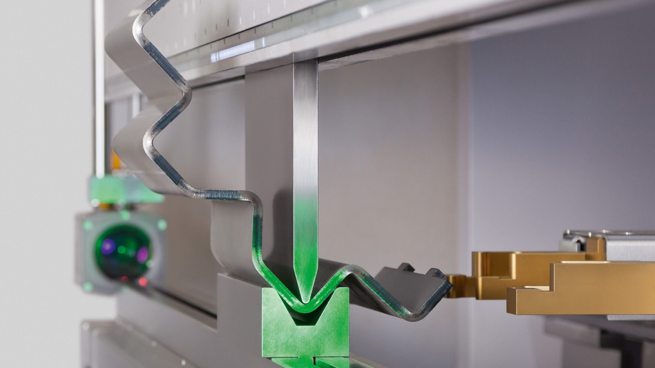
The working logic of Press Brake: Plate positioning → Die extrusion (force + shape control) → Plastic deformation + springback compensation → Precise forming of parts Through the trinity mechanism of "drive system provides power, die defines shape, and CNC system guarantees accuracy", Press Brake realizes the efficient transformation of metal plates from plane to three-dimensional, and is an indispensable core equipment for sheet metal processing in modern manufacturing.


2.What are the main components of a press brake?
The frame is mainly composed of left and right columns, a workbench, and a crossbeam. The left and right oil cylinders are fixed on the columns. The slider is connected to the piston of the oil cylinder and moves up and down along the guide rail fixed on the column. The lower die is fixed on the workbench, and the upper die is installed at the lower end of the slider. The hydraulic system provides power, and the electrical system gives instructions. Under the action of the oil cylinder, the slider drives the upper die downward and closes with the lower die to achieve sheet bending. The left and right columns, the workbench, and the slider (hereinafter referred to as the three major parts) are the key parts of the Press Brake. The sum of the weight of the three major parts accounts for 70% to 80% of the total weight of a Press Brake. Its strength and rigidity directly determine the operating accuracy, service life, and accuracy of the workpiece of the machine tool.
Rack part:
- Slider part: hydraulic transmission is adopted, and the slider part is composed of a slider, a cylinder and a mechanical stopper fine-tuning structure. The left and right cylinders are fixed on the frame, and the piston (rod) drives the slider up and down through hydraulic pressure, and the mechanical stopper is controlled by the numerical control system to adjust the value;
- Workbench part: the button box is operated to drive the motor to move the material stopper forward and backward, and the moving distance is controlled by the numerical control system, and the minimum reading is 0.01 mm (there are travel switch limits at the front and rear positions);
- Synchronous system: The machine is composed of a mechanical synchronous mechanism composed of a torsion shaft, a swing arm, and a joint bearing, which has a simple structure, stable and reliable performance, and high synchronization accuracy. The mechanical stopper is adjusted by the motor, and the numerical control system controls the value;
- Material stopper mechanism: The material stopper adopts motor transmission, and the two screws are driven to move synchronously through chain operation, and the numerical control system controls the size of the material stopper.
Mould system
- Upper die (convex die): installed on a slider that can move up and down, the shape determines the bending profile (such as V-shaped, arc-shaped, Z-shaped, etc.).
- Lower die (concave die): fixed on the workbench, providing support and bending notch, the notch width affects the bending force and bending radius.
- Key role: The mold gap needs to match the thickness of the plate. For example, when bending thick plates, a wide notch lower die is required to prevent the plate from being squeezed and cracked.


Drive system:
- Hydraulic drive (most common): The slider is pushed downward by the hydraulic cylinder, with strong power (bending force can reach hundreds to thousands of kilonewtons), suitable for thick plates or large workpieces, features: smooth operation, high precision, CNC hydraulic Press Brake can achieve ±0.1° angle control.
- Mechanical drive: driven by motors, gears, screws, etc., with low power, suitable for thin plates (such as ≤3mm steel plates) or small processing, low cost.
- Manual drive: manual operation handle or pedal, only used for simple processing (such as bending small parts at the maintenance site).
CNC system (CNC): The "brain" of modern Press Brake, which can input parameters (such as bending angle, plate thickness, mold type) and automatically calculate the slider stroke and pressure. Supports storage of multiple sets of processing programs, one-click switching of bending processes for different workpieces, suitable for mass production.
3.What are the electrical components of the Press Brake?
The electrical system of a Press Brake is critical for precise control and efficient operation. The key components are described in detail below.
Press Brake Control System
- The control system is the core intelligence of the Press Brake, usually using a CNC (computer numerical control) or NC (numerical control) unit. The system interprets data from various sensors, effectively manages the movement of the press head and the position of the back gauge, and adjusts the bending angle according to the operator's input.
- The operator enters data such as part geometry, material thickness and required bending angle into the control system, and the system calculates and performs the necessary operations. Advanced control systems can store multiple bending programs, thereby improving repeatability and reducing setup time for subsequent jobs.
- In addition, real-time feedback from a linear scale or encoder helps to make precise adjustments to the position of the punch head and compensate for any mechanical deflection called springback, thereby ensuring the accuracy of each bend.
Motors and drives
- The motor and drive are the basic components that provide the power required for the various movements of the press brake.
- The electric motor is responsible for driving the hydraulic pump, powering the punch, and moving the back gauge to accurately position the metal sheet. In a servo-electric press brake, the servo motor directly drives the punch movement through a mechanical linkage such as a belt, pulley or ball screw, thus achieving high precision and high energy efficiency.
- The drive controls the speed and torque of the motor to adapt the power output to the operating requirements. Using a variable frequency drive (VFD) can further improve energy efficiency by adjusting the motor speed according to the load, reducing power consumption and wear on mechanical components.
Electrical Panels and Wiring
- Switchboards are the central location where various electrical components such as circuit breakers, relays, and contactors are installed. These panels are responsible for distributing power to the press brake and protecting the system from electrical overloads. Orderly and clearly labeled wiring within the switchboard is essential for efficient troubleshooting and maintenance.
- In addition, these panels often contain PLC or CNC controllers that interact with the machine's user interface, providing a centralized point of control for the operator. Regular inspections are essential to ensure there are no loose connections or signs of overheating, which can cause machine failure.
- In addition, enclosures are used to protect sensitive electronics from environmental contaminants such as dust and metal shavings that can impair their functionality.
Human Machine Interface (HMI)
- The Human Machine Interface (HMI) is the key point of interaction between the operator and the Press Brake. Modern HMIs are often equipped with intuitive touch screens that are easy to navigate and allow the operator to quickly input bending parameters.
- They display important diagnostic information and monitor production metrics such as bend angle and cycle time. The ability to store and retrieve pre-programmed part sequences not only reduces errors, but also significantly reduces setup time.
- In addition, some HMIs integrate advanced features such as 2D or 3D bending simulations, which help visualize the final product shape and identify potential collision points before actual production begins. This level of interaction ensures that operators can achieve high production efficiency while maintaining precise control over the bending process.
- Safety Features
Safety is of utmost importance during Press Brake operation. Its electrical system contains many features designed to protect the operator and the equipment. The main safety mechanisms include
- Light Curtains: emit infrared light that stops the ramming instantly when blocked, preventing accidents.
- Guards or Fences: These physical barriers prevent unauthorized access to the Press Brake’s moving parts, increasing operational safety.
- Emergency Stop Buttons: These buttons are strategically located around the machine and allow the operator to quickly cut power and stop all movement in an emergency.
- Pressure Sensing Valves: These valves are critical in preventing over-pressurization of the hydraulic system. They automatically divert fluid if pressure exceeds a preset limit, protecting the safety of the machine and operator.
- Two-hand Controls: These controls are designed to keep the operator’s hands away from the pinch zone during machine operation, requiring the operator to use both hands to activate the ram, further enhancing safety measures.
4.What are the differences in parts between different types of Press Brakes?
(1)Hydraulic Press Brake is powered by a hydraulic system and is one of the most commonly used types in the industry. It is suitable for bending large, high-strength plates.
Core component features
1.1 Press Brake Powertrain
- Hydraulic pump: provides hydraulic power. Common types include gear pumps, vane pumps or plunger pumps. They have high pressure (up to tens of MPa) and stable output power.
- Hydraulic cylinder: usually a double-cylinder or multi-cylinder structure, which pushes the slider (upper die) downward to complete the bending. The cylinder body is mostly made of high-strength steel or cast iron, and the internal surface is precisely ground to ensure sealing.
- Hydraulic valve: including overflow valve (control pressure), reversing valve (control the direction of movement of the hydraulic cylinder), throttle valve (regulate flow), etc., used to accurately control the pressure and speed of the hydraulic system.
1.2 Press Brake Body structure
- Frame: It adopts an integral welded structure or a cast structure (such as a steel plate welded frame), which has high strength and good rigidity. It needs to be aged to eliminate internal stress and avoid deformation after long-term use.
- Workbench: Install the lower mold, with a T-slot or mold seat on the surface for fixing the mold. The material is mostly wear-resistant cast iron or steel.
- Slider: Install the upper mold, driven up and down by a hydraulic cylinder, with high bottom surface processing accuracy to ensure parallelism and verticality with the lower mold.
1.3 Press Brake die and punch system
- Upper die: Common types include sharp knife die, arc die, etc., made of high-hardness tool steel (such as Cr12MoV), and surface quenched (hardness can reach HRC55-60).
- Lower die: Usually a V-shaped die, the notch width is adjusted according to the thickness of the plate and the bending angle, the material is similar to the upper die, and some high-precision molds require coating (such as hard chrome plating) to improve wear resistance.
1.4 Press Brake Auxiliary components
- Material stopper: driven by a material stopper, screw or servo motor, used to locate the bending position of the plate with high accuracy (error ±0.1mm).
- Deflection compensation device: Large hydraulic Press Brake is often equipped with a mechanical or hydraulic deflection compensation mechanism to offset the deformation of the frame and slider under heavy load and ensure bending accuracy.
(2) Mechanical Press Brake
Mechanical Press Brake provides power through mechanical transmission (such as gears, crankshafts), with simple structure and low cost, and is suitable for bending processing of small workpieces or with low precision requirements.
2.1 Press Brake Powertrain:
- Motor and reducer: The motor drives the crankshaft to rotate through a belt or gear reducer, converting the rotational motion into the up and down linear motion of the slider. The power output is softer than the hydraulic system, but the torque is limited.
- Crankshaft and connecting rod: The crankshaft is the core transmission component, made of medium carbon alloy steel (such as 45# steel or 40Cr), and is tempered to improve the comprehensive mechanical properties; the connecting rod connects the crankshaft and the slider to transmit power.
2.2 Press Brake Body structure
- Frame: Mostly made of cast iron, compact but less rigid than hydraulic press brake, suitable for light load conditions.
- Sliders and guide rails: The slides are driven by the crankshaft, and the guide rails are usually sliding guide rails (such as copper alloy guide rails), which have low precision, wear quickly, and need to be lubricated regularly.
2.3 Press Brake Mould system
The mold type is similar to the hydraulic press brake, but the material and precision are lower. Ordinary tool steel (such as T10A) is often used, with a surface hardness of HRC50-55, which is suitable for bending thin plates (thickness ≤3mm).
2.4 Press Brake Auxiliary parts
- Manual stopper: The stopper position is adjusted by a screw or handwheel, with low accuracy (error ±1mm), and relies on manual operation.
- No deflection compensation device: Due to the small processing load, compensation mechanism is usually not equipped.
(3) CNC/NC Press Brake
CNC Press Brake is an upgrade of hydraulic or mechanical Press Brake. It controls the movement of each axis through the CNC system. It has high precision and high degree of automation, and is suitable for batch processing of complex workpieces.
3.1 Press Brake Control System
- CNC system: such as DELEM, Cybelec or domestic systems, control multi-axis motion such as X-axis (stopper position), Y-axis (slider stroke), Z-axis (mold inclination), support programming input of bending angle, speed, pressure and other parameters, with an accuracy of ±0.01mm.
- Servo motor and driver: drive stopper, slider and other components, fast response speed and precise positioning (such as servo motor + ball screw transmission)
3.2 Press Brake Powertrain and drivetrain
- Servo hydraulic system (some high-end models): using servo motor to drive hydraulic pump, supply oil on demand, low energy consumption, low noise, with proportional valve to achieve precise control of pressure and speed.
- Ball screw or linear guide: replace traditional sliding guide, high transmission efficiency, low wear, improve the movement accuracy of slider and material stopper.
3.3 Press Brake Body and detection device
High rigidity frame: structural optimization design (such as integral welding + prestressed tie rod), with laser detection or grating ruler to feedback the slider position in real time, and dynamically compensate for deflection error.
Angle detection sensor: integrated laser goniometer or encoder, real-time detection of bending angle, closed-loop control to ensure accuracy (error ±0.1°).
3.4 Press Brake Molds and automation components
- Quick-change mold system: adopts modular design, quickly changes molds through hydraulic or mechanical clamping devices, and improves production efficiency.
- Automatic loading and unloading device: high-end models are equipped with robots or conveyor belts to realize fully automatic loading, bending, and unloading processes.
5.How to maintain and extend the service life of Press Brake parts
5.1Hydraulic system (Hydraulic Press Brake / CNC Press Brake)
Hydraulic oil management:
Regular replacement: The hydraulic oil of a new device should be replaced 3 months after the first operation, and then every 1-2 years (adjusted according to the frequency of use and working conditions) to avoid oil contamination or oxidation deterioration.
Filtration and cleaning: Check the hydraulic oil filter element (return filter element, oil suction filter element) every month, and clean or replace it in time when it is blocked; clean the oil tank every year to remove sediment and impurities.
Oil monitoring: Use an oil tester to regularly test the viscosity, moisture, and acid value, and immediately deal with it if the oil is emulsified or the impurities exceed the standard.
Hydraulic cylinders and seals:
Check for leaks: inspect the cylinder piston rod surface daily. If there is oil leakage, replace the seal ring (common materials are nitrile rubber or polyurethane) in time to prevent dust from entering the cylinder and wearing the inner wall.
Piston rod protection: apply anti-rust grease regularly and install a dust cover to prevent iron filings and coolant from adhering to cause abnormal wear of the seal ring.
Hydraulic valve group:
Avoid vibration and looseness: Tighten the valve assembly mounting bolts regularly to prevent oil leakage from the interface or valve core jamming due to vibration.
Valve core cleaning: If pressure instability or abnormal movement occurs, disassemble the valve core to check if there are impurities blocking it, clean it with kerosene and reinstall it (non-professionals should not operate without authorization).
5.2Mechanical transmission system (mechanical press brake / CNC press brake)
Motor and reducer:
Heat dissipation and lubrication: Keep the motor fan clean to avoid dust accumulation that affects heat dissipation; replace the reducer gear oil every 2 years, and replenish it in time when the oil level is insufficient (the gear oil model must match the equipment manual).
Belt/gear inspection: Check the tension of the transmission belt every week, and replace it in time if wear, cracks or slippage are found; gear transmission needs to regularly clean the iron filings on the tooth surface and apply grease (such as lithium-based grease) to prevent rust.
Crankshaft and connecting rod:
Lubrication point maintenance: Regularly add grease according to the grease nozzle position marked on the equipment (usually once every 8-hour working cycle) to ensure that there is no dry grinding noise at the hinge connection.
Clearance detection: Use a feeler gauge to measure the clearance between the crankshaft and the bearing every year. Replace the bearing or bearing when it exceeds the tolerance (such as 0.1mm) to avoid a decrease in transmission accuracy due to excessive clearance.
5.3 Press Brake Maintenance of body and moving parts
Racks and workbenches
Sliding guide rails (mechanical press brakes) are filled with lubricating oil (such as 32# mechanical oil) through the oil cup every day to keep the oil film on the guide rail surface uniform; remove the guide rail cover every quarter, remove the accumulated iron filings and oil stains, and check the wear of the guide rail (if obvious grooves appear, they need to be ground or replaced).
Ball screw / linear guide rails (CNC press brakes) :Wipe the guide rail surface with a clean cloth every week and add grease (such as precision mechanical grease) through the oiling nozzle:Check the preload of the screw nut pair regularly, and contact the manufacturer for adjustment if looseness or abnormal noise is found.
Slider parallelism adjustment: Use a micrometer to check the parallelism of the bottom surface of the slider and the workbench every year (error ≤0.05mm/m), and correct it through the hydraulic system or mechanical adjustment mechanism to avoid aggravation of unilateral wear.
Slides and guide rails
5.4 Mold system maintenance
Daily use specifications
Correct installation and disassembly: When installing the mold, use special tools (such as copper rods) to tap it gently to avoid hitting the surface of the mold; clean the iron filings and oil stains on the mold in time after disassembly, and do not stack them to avoid crushing the cutting edge.
Avoid overloading: Strictly process according to the maximum bending thickness and length of the mold, and do not use small-sized molds to bend thick plates (such as using V10 lower molds to bend 8mm steel plates) to prevent the mold from breaking or deforming.
Cleaning and rust prevention
After each use: use compressed air to blow away the iron filings in the groove of the mold, wipe the surface with a rag dipped in kerosene or special cleaner, and apply anti-rust oil (such as WD-40) to prevent rust.
Long-term storage: The mold should be hung vertically or placed flat on a drying rack to avoid contact with humid air; check the inventory mold regularly (every 3 months) and re-apply anti-rust grease.
Wear repair
Minor wear: Use oilstone or grinding paste to gently grind the burrs on the cutting edge and restore the surface roughness (Ra≤1.6μm).
Severe wear: When the bending angle deviation of the mold exceeds 5° or the cutting edge cracks, it needs to be returned to a professional manufacturer for quenching repair or replacement of a new mold (self-made molds must ensure that the material is consistent with the original one, such as Cr12MoV).
5.5Maintenance of CNC system and testing equipment
CNC system
Dust prevention and heat dissipation: Clean the control cabinet fan filter regularly (once a month) to ensure that the internal temperature is below 40°C to avoid short circuits on circuit boards or aging of components due to dust accumulation.
Battery replacement: The system lithium battery (used to save program data) needs to be checked annually and replaced in time when the voltage is lower than 3V (the model is usually CR2032). Avoid power outages and parameter loss during the replacement process.
Servo motors and sensors
Motor encoder protection: Do not collide with the encoder at the rear end of the motor. Check the connection line regularly (once every quarter) to prevent positioning inaccuracy due to signal interruption.
Detection device calibration: Use a standard angle block to calibrate the laser goniometer or grating ruler every year. Recalibrate when the error exceeds ±0.1°; the surface of the linear displacement sensor (such as the magnetic scale) must be kept clean to avoid iron filings interfering with the reading.
5.6Reference for replacement cycle of wearing parts
| Parts | Normal service life | Replacement signal | Maintenance recommendations |
| Hydraulic seals | 1-2 years | Oil leakage, slow movement | Clean the cylinder when replacing and use special tools to install |
| Drive belt | 1-3 years | Cracks, slippage, wear and fuzzing | Adjust the tension to the standard value when replacing |
| Guide rail lubricating oil pipe | 3-5 years | Aging, cracking, blockage | Use compressed air to clear the pipe regularly |
| Die spring | 500,000 bends | Elasticity reduction, | breakage Replace in pairs to avoid uneven pressure |
| Ball screw nut pair | 5-8 years | Abnormal noise, reduced positioning accuracy | Regularly add grease and check preload |
5.7 Core Principles of Life Extension
- Standard operation: set the pressure, speed and bending parameters strictly according to the instructions, and do not use beyond the range.
- Regular inspection: establish equipment maintenance records, record the content of each maintenance and replacement parts information, and facilitate tracing problems.
- Environmental control: keep the workshop clean and dry, control the temperature at 5-40℃, humidity <80%, and avoid dust and corrosive gases.
- Professional maintenance: when complex components (such as hydraulic systems, CNC systems) fail, give priority to contacting the original factory technicians to handle, to avoid self-disassembly and expansion of damage.
Through a systematic maintenance strategy, the life of Press Brake components can be significantly extended (e.g. mold life can be extended by 30%-50%, and the frequency of hydraulic system failures can be reduced by 60%), while processing efficiency and product quality can be improved to maximize the return on equipment investment.