Press brake tooling is one of the smallest-looking items in a sheet metal bending quotation, but in real production it can decide whether a press brake becomes a profitable machine or a daily bottleneck. A modern press brake may have a rigid frame, accurate CNC controller, reliable hydraulic or servo system, automatic crowning, and multi-axis backgauge, but the bend still happens at the contact point between the punch, the sheet, and the lower die. If that contact is wrong, the rest of the machine cannot fully correct the problem.
At KRRASS, we often review bending requirements from buyers who already know the tonnage and bending length they want. They may ask for a 160-ton 3200 mm machine, a 220-ton 4000 mm machine, or a servo-electric press brake for thin stainless steel parts. Those headline specifications are important, but they are not enough. The actual production result depends on material type, thickness, bending length, inside radius, flange length, bend sequence, surface requirement, tool height, tool load capacity, clamping style, crowning, backgauge movement, and operator workflow. Tooling connects all these factors.
This article is written for purchasing teams, production managers, engineers, and fabricators who want to avoid expensive tooling mistakes before they happen. The goal is not to make tooling selection difficult. The goal is to make it practical. If you can identify the common mistakes, you can prepare better drawings, ask better questions, build a more realistic tooling package, and choose a press brake configuration that supports your real parts instead of only looking good on a quotation sheet.
Table of Contents
Why press brake tooling mistakes are so expensive
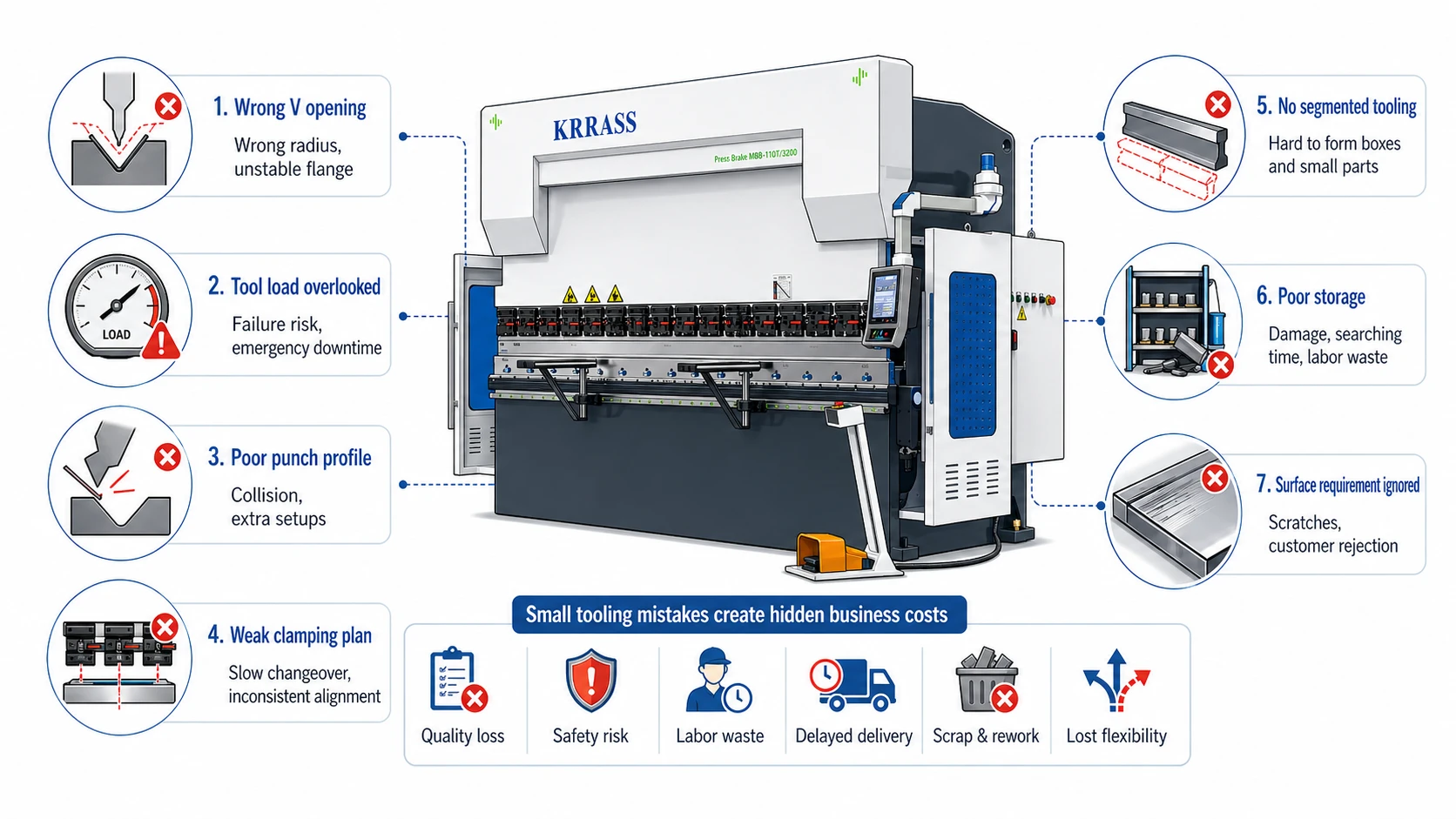
A press brake tooling mistake rarely appears as one single problem. It usually appears as many small losses repeated every day. The operator spends more time on trial bends. The first-off part is rejected. The angle changes from the left side to the right side. Stainless steel panels show visible marks. Short flanges become unstable in the die. Boxes collide with a straight punch. Tool segments are difficult to align. The drawing requires an inside radius that the selected die cannot produce. The machine has enough nominal tonnage, but the tooling does not have enough load capacity. Each issue may look manageable, but the total cost can become larger than the price difference between a basic tooling package and a correctly engineered one.
The commercial impact is especially serious for factories that handle many small and medium batches. In those factories, setup time is often as important as bending speed. If each order needs multiple tool changes, segmented tooling, accurate clamping, and reliable storage, a poor tooling system can slow the entire factory. This is why our press brake tooling guide treats tooling as part of the bending system rather than a simple accessory.
| Tooling mistake | Visible production problem | Hidden business cost | Better decision |
|---|---|---|---|
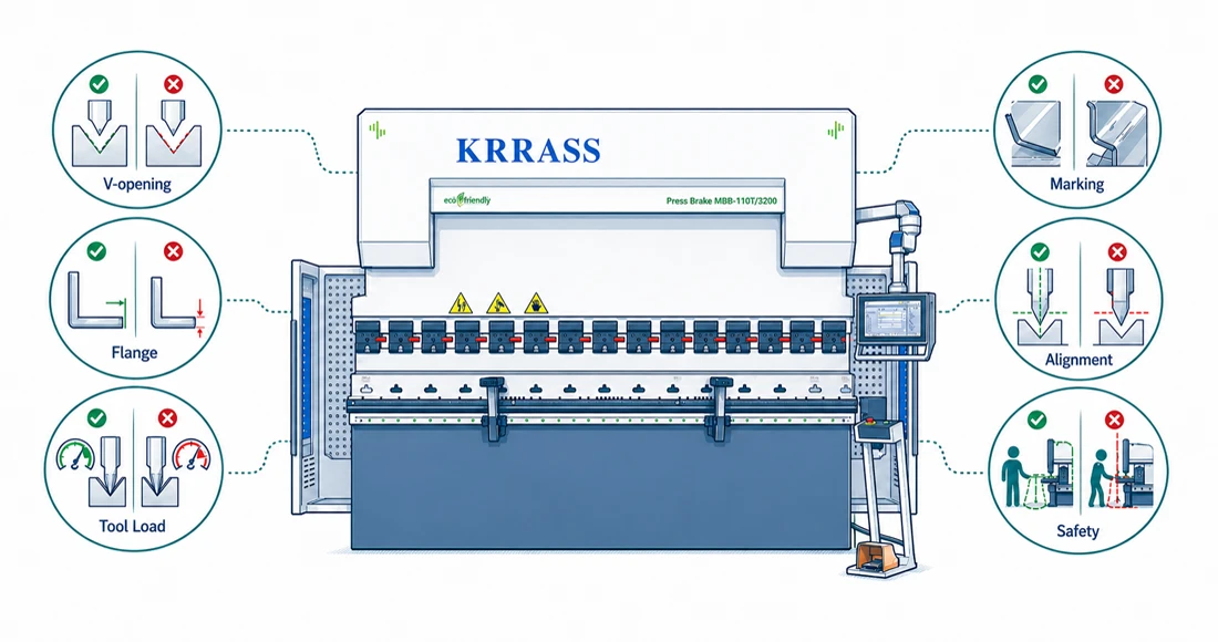
| Wrong V opening | Wrong radius, excessive marking, unstable flange | Scrap, rework, delayed delivery | Match V opening to thickness, radius, tonnage, and flange length |
| Tool load overlooked | Tool deformation or failure risk | Safety risk, emergency downtime | Check tool rating in tons per meter before production |
| Poor punch profile | Collision with formed flanges | Extra setups, lost flexibility | Review bend sequence and clearance before ordering |
| Weak clamping plan | Slow tool change and inconsistent alignment | Longer setup time, more operator dependence | Use suitable manual, quick, or hydraulic clamping |
| No segmented tooling | Boxes and small parts are difficult to form | Outsourcing, extra welding, redesign | Build segmented punch and die sets for product mix |
| Poor storage | Damaged tools and slow searching | Reduced tool life and labor waste | Use labeled storage, tool carts, or tool stations |
| Ignored surface requirement | Scratches on stainless or coated sheet | Customer rejection, polishing cost | Use proper die shoulder radius, films, urethane, or anti-marking solutions |
The table above is simple, but it shows a key point: tooling mistakes affect quality, safety, labor, and delivery. They are not only technical mistakes. They are business mistakes.
Mistake 1: choosing the press brake first and the tooling later
One of the most common buying mistakes is selecting the machine first and leaving tooling until the end. This usually happens because the buyer sees the press brake as the main investment and the tooling as a small add-on. In reality, the machine and the tooling should be selected together.
A press brake is a force-generating and positioning system. Tooling is the forming interface. The machine provides tonnage, stroke, opening height, ram repeatability, backgauge positioning, crowning, and safety functions. The tooling converts those capabilities into a specific bend geometry. If the tooling does not match the work, the machine cannot deliver its full value.
For example, a factory making electrical cabinets may not need extreme tonnage, but it may need segmented gooseneck punches, accurate backgauge positioning, and quick tool change. A factory making long construction panels may need a long bed, careful crowning, and dies that support long bends without excessive deflection. A stainless steel kitchen equipment producer may care more about surface protection and consistent radius than maximum pressure. A heavy bracket manufacturer may need higher tonnage, stronger dies, larger V openings, and special attention to tool load capacity.
The better workflow starts with the part. Before choosing a machine and tool package, collect material grade, thickness range, maximum bend length, common bend length, minimum flange length, bend angles, inside radius requirements, annual or monthly volume, surface requirements, part drawings, and future product plans. If drawings are not available, prepare sample photos and product descriptions. A good press brake recommendation should connect the machine frame, controller, backgauge, crowning, clamping, and tooling to the real parts.
At KRRASS, we prefer to review part drawings before finalizing tooling. If a buyer can provide common product drawings, we can identify whether standard tooling is enough, whether segmented tooling is necessary, whether gooseneck clearance is required, whether hemming tools are needed, or whether special tooling should be planned. This reduces the risk of buying a machine that is strong enough in theory but poorly matched to the factory's daily work.
Mistake 2: using one V opening for too many materials
The lower die opening is one of the most important tooling decisions in air bending. A common starting rule is that the V opening is approximately eight times the material thickness for many mild steel air-bending applications. The rule is useful because it gives a balanced relationship between required tonnage, inside radius, minimum flange length, and marking. However, it is only a starting point, not a universal law.
In air bending, the die opening strongly influences the inside radius. Industry guidance from The Fabricator notes that when air bending mild steel, the inside bend radius forms at approximately 16 percent of the V-die opening. That means a 16 mm V opening may produce an inside radius of around 2.6 mm in mild steel, while a 32 mm V opening may produce a radius of around 5.1 mm. Material type, tensile strength, grain direction, thickness, and tooling condition still matter, but the die opening remains a major driver.
The die opening also influences tonnage. A wider V opening usually reduces bending force, but it increases the inside radius and minimum flange length. A narrower V opening can help produce shorter flanges and smaller radii, but it raises tonnage and may increase marking. This trade-off is why a factory should not use one die opening for every job.
| Material thickness | Common starting V opening for air bending | Approx. inside radius for mild steel at 16% of V | Approx. minimum flange planning value at 70% of V | Practical note |
|---|---|---|---|---|
| 1.0 mm | 8 mm | 1.3 mm | 5.6 mm | Good for thin sheet, but cosmetic surfaces need care |
| 1.5 mm | 12 mm | 1.9 mm | 8.4 mm | Common for enclosures and light cabinets |
| 2.0 mm | 16 mm | 2.6 mm | 11.2 mm | Practical starting point for many mild steel parts |
| 3.0 mm | 24 mm | 3.8 mm | 16.8 mm | Check tonnage and flange length before production |
| 4.0 mm | 32 mm | 5.1 mm | 22.4 mm | Crowning and die marking become more important |
| 6.0 mm | 48 mm | 7.7 mm | 33.6 mm | Tool load and machine tonnage must be checked carefully |
| 8.0 mm | 64 mm | 10.2 mm | 44.8 mm | Heavy work may need a larger machine and stronger tooling |
These numbers are planning values, not final production guarantees. They are useful during quotation review because they show the relationship between thickness, V opening, radius, and flange length. If a drawing specifies a 2 mm material with a 6 mm flange, a V16 die may not support the flange safely. If the same drawing specifies a very tight inside radius, the tool plan must be reviewed before promising production feasibility.
A practical die library should cover the factory's real thickness range. A job shop bending 1 mm to 6 mm sheet cannot expect one die to handle every part efficiently. It may need V6, V8, V12, V16, V24, V32, V40, and V50 or similar openings, depending on local standards and product mix. The exact list depends on the materials and parts, but the principle is the same: V opening selection must be intentional.
Mistake 3: ignoring minimum flange length
Minimum flange length is often forgotten because many buyers focus first on thickness and angle. In real production, however, the flange must sit safely on the die shoulders during bending. If the flange is too short for the V opening, the sheet may slip, become unstable, or fall into the die. The bend angle may become inconsistent, and the operator may have to hold the part in an unsafe or uncomfortable way.
A simple planning rule is that minimum flange length is often around 70 percent of the V opening. This is not a fixed standard because die shoulder radius, die angle, material thickness, punch geometry, and bend angle all influence the actual limit. Still, it is a useful early warning tool.
For example, if a part has a 10 mm flange, a V16 die may be possible as a starting point because 70 percent of 16 mm is 11.2 mm, but the margin is small. If the same part uses a V24 die, the approximate planning flange becomes 16.8 mm, which may be too large. The operator may be forced to use a narrower die, which increases tonnage and marking. This is why the flange requirement must be considered together with tonnage and radius.
Minimum flange length is especially important for boxes, trays, electrical enclosures, elevator panels, HVAC parts, door frames, and thin stainless steel parts. These products often include short returns and multiple bends near the edge. If the tooling plan ignores the shortest flange, the factory may discover the problem only after the machine is installed.
The solution is simple: list the shortest flange for each common thickness and material. Then compare it with the planned die openings. If the flange is too short, consider a narrower V opening, a special die, a modified bend sequence, or a design change. The right decision should be made before production, not during a rushed trial bend.
Mistake 4: assuming machine tonnage and tool capacity are the same thing
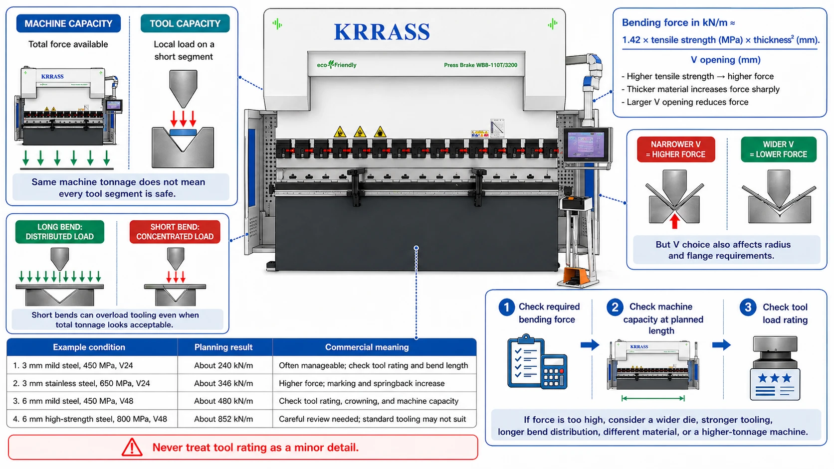
Another serious mistake is assuming that a press brake rated at 160 tons can safely apply 160 tons through any tool segment. Machine capacity and tool capacity are different. A machine may have enough total force, but the punch or die may have a lower load rating, especially if the bend is short and force is concentrated in a small tool section.
Tooling is usually rated by load per meter or load per foot. A long bend distributes force across a longer length. A short bend concentrates force into a shorter segment. If an operator bends a small bracket with high tonnage over a short length, the local tool load can become dangerous even if the total machine tonnage looks acceptable.
A simplified planning formula for air bending force is:
Bending force in kN per meter ≈ 1.42 × tensile strength in MPa × material thickness² in mm / V opening in mm
This formula is a planning estimate for comparison, not a substitute for the machine manufacturer's calculation, tooling supplier rating, or production test. It is useful because it shows the relationship clearly. Higher tensile strength increases force. Thicker material increases force dramatically because thickness is squared. A larger V opening reduces force, but it changes radius and flange requirements.
| Example condition | Planning result | Commercial meaning |
|---|---|---|
| 3 mm mild steel, 450 MPa tensile strength, V24 | About 240 kN/m | Often manageable, but check tool rating and bend length |
| 3 mm stainless steel, 650 MPa tensile strength, V24 | About 346 kN/m | Higher force than mild steel; marking and springback also increase |
| 6 mm mild steel, 450 MPa tensile strength, V48 | About 480 kN/m | Tool rating, crowning, and machine capacity must be checked |
| 6 mm high-strength steel, 800 MPa tensile strength, V48 | About 852 kN/m | Requires careful review; standard tooling may not be suitable |
The mistake becomes more dangerous when a factory uses narrow dies to achieve short flanges or tight radii. Narrow dies increase force. If that force exceeds the tool rating, the tool can deform, crack, or fail. Even before failure, overloaded tooling can produce inconsistent angles and poor repeatability.
The better practice is to check three things before production: required bending force, machine capacity at the planned length, and tool load rating. If the force is too high, consider a wider die opening, a stronger tool, a longer bend distribution, a different material, or a higher-tonnage machine. Never treat tool rating as a minor detail.
Mistake 5: ignoring material behavior and springback
Different materials do not bend the same way. Mild steel, stainless steel, aluminum, galvanized sheet, pre-painted sheet, and high-strength steel all behave differently under bending pressure. The tooling plan must respect these differences.
Mild steel is generally forgiving, which is why many tooling rules of thumb are based on it. Stainless steel usually has higher tensile strength and more springback, so it often needs more bending force and better control of angle compensation. Aluminum can be softer and more marking-sensitive, but some aluminum grades crack more easily if the bend radius is too small. High-strength steel needs much more caution because it can require higher force, larger radii, and tooling with sufficient load capacity.
ISO 7438, the international standard for metallic materials bend testing, describes bend testing as a method for determining the ability of metallic materials to undergo plastic deformation in bending. In production, the lesson is practical: material ductility matters. If the selected tooling forces the material beyond its forming ability, cracks, surface damage, or dimensional failure can occur.
| Material | Typical tooling concern | Common mistake | Better approach |
|---|---|---|---|
| Mild steel | Balanced tonnage, radius, and flange length | Assuming all materials behave like mild steel | Use mild steel rules only as a starting point |
| Stainless steel | Higher strength, springback, and marking risk | Using the same setup as low-carbon steel | Check force, overbend strategy, die surface, and protection |
| Aluminum | Surface marking and cracking risk in some grades | Using too sharp a punch radius | Confirm grade, temper, grain direction, and minimum radius |
| Galvanized sheet | Coating damage and visible marks | Excessive die pressure or dirty tools | Keep tools clean and use appropriate die shoulders or film |
| High-strength steel | High force and larger springback | Underestimating tonnage and tool load | Use larger radii, stronger tooling, and engineering review |
| Pre-painted sheet | Cosmetic protection | Treating it like unfinished steel | Use anti-marking measures and strict handling procedures |
Material behavior also affects bend allowance and flat pattern development. If the inside radius changes because the die opening changes, the flat pattern must change too. If the material springs back more than expected, the CNC program and tool angle strategy must compensate. A tooling mistake can therefore create errors not only at the press brake but also in laser cutting, punching, and upstream blank preparation.
The best solution is to standardize bending data for common materials. Build a practical database that includes material grade, thickness, V opening, punch type, inside radius, angle correction, and surface protection method. Modern CNC controls can support tool libraries and bending programs, but the data must come from real production experience.
Mistake 6: chasing a very sharp inside radius without checking feasibility
Many drawings show a sharp internal corner because it looks clean in CAD. In sheet metal bending, a sharp-looking drawing can create real production problems. A very small inside radius may require a narrow V opening, high tonnage, a sharp punch tip, and a ductile material. If the material cannot tolerate the deformation, cracking may occur on the outside of the bend. If the punch tip is too sharp, it can crease the material, accelerate tool wear, and increase surface damage.
In air bending, the inside radius is mainly controlled by the V opening, not only by the punch tip. A punch tip that is too sharp does not automatically produce a better part. It may penetrate or coin the material unintentionally, especially when high pressure is used. For many commercial parts, a stable and repeatable radius is more valuable than the smallest possible radius.
A realistic inside radius should be discussed during design and quotation. If the product does not require a sharp radius for assembly or appearance, allow a radius that matches standard tooling. This reduces tooling cost, lowers tonnage, improves repeatability, and extends tool life. If the product does require a tight radius, the material grade, grain direction, punch radius, die opening, tool capacity, and bend test should be reviewed carefully.
This is also where communication between design, purchasing, and production matters. A designer may specify a tight radius without knowing the press brake tooling limitations. A purchasing team may request the lowest machine price without including the special tooling needed. A production team may then struggle to make the part. A short technical review before purchase can avoid all three problems.
Mistake 7: choosing a punch profile without checking collision
The upper punch is not selected only by angle and radius. Its height, shape, throat, gooseneck clearance, load capacity, and mounting style all matter. Collision problems often appear after the first bend, when a flange or return wall begins to occupy space near the punch. A straight punch may work for the first bend but collide with the part during the second or third bend.
Gooseneck punches help with boxes, pans, U-shaped parts, return flanges, and deep channels. However, gooseneck tools have load limits because their shape reduces stiffness compared with some straight punches. Choosing a gooseneck punch only because it provides clearance is not enough. The tool must also be strong enough for the material, thickness, bend length, and V opening.
Punch height also matters. A taller punch may provide more clearance, but it changes open height requirements and may reduce available stroke margin. If the press brake has limited daylight, stroke, or throat depth, a tall tool combination may restrict the part. This is especially important for older machines, small machines, and deep box bending.
The correct workflow is to review the bend sequence. A simple flat drawing is not enough for complex parts. The team should simulate or mentally trace each bend in order: which flange is bent first, where the part rotates, where the backgauge fingers contact, and where the formed part might hit the punch, die, ram, clamps, or machine frame. CNC bending software and 3D simulation can help, but even a careful manual review is better than choosing tools from a catalog without checking clearance.
Mistake 8: treating segmented tooling as optional for flexible production
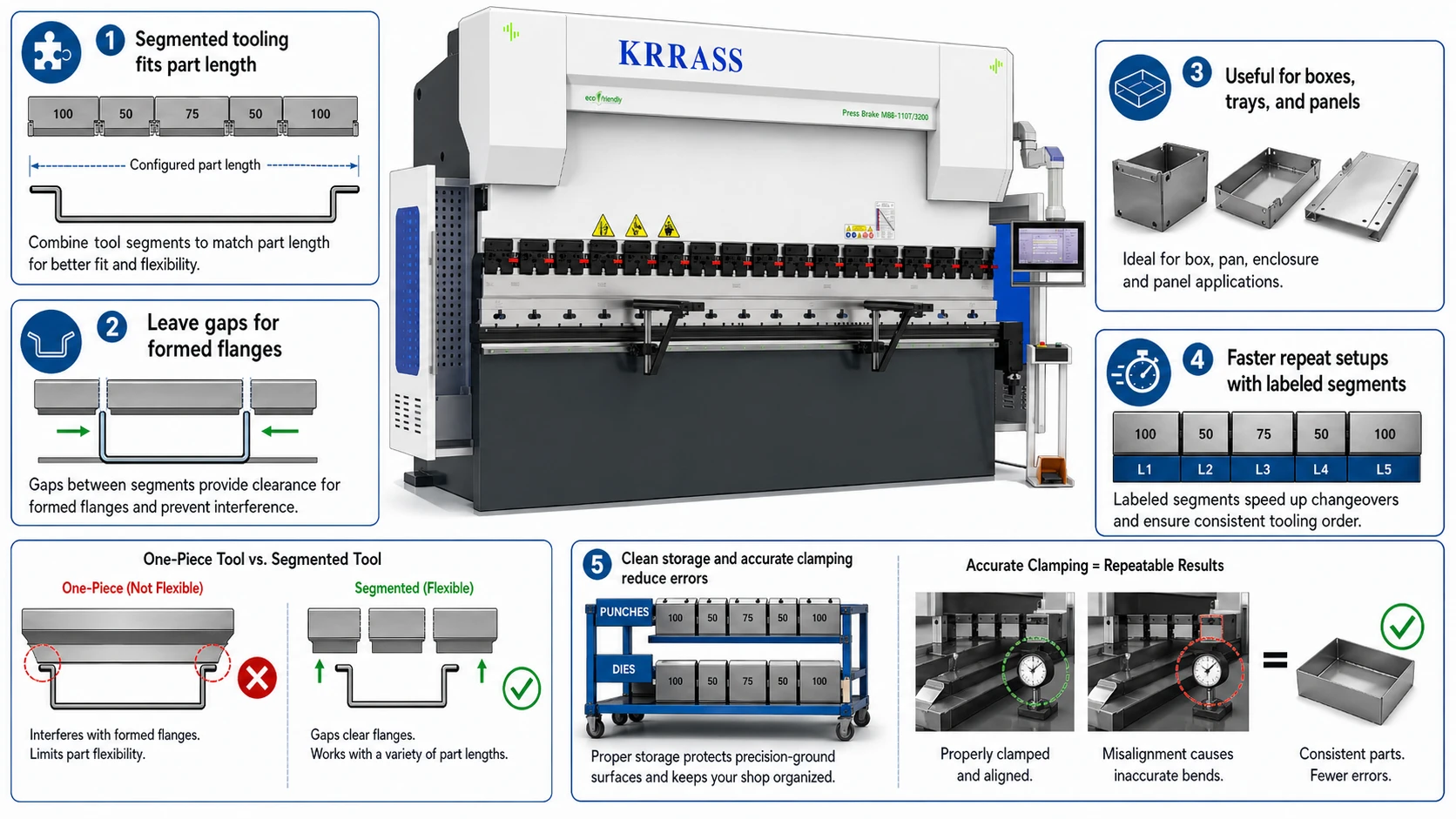
Long one-piece tools may be useful for simple long bends, but many factories need segmented tooling for real flexibility. Segmented punches and dies allow operators to combine sections to match part length, leave gaps for already formed flanges, and bend boxes or pans without cutting tools each time.
A factory that makes cabinets, electrical boxes, drawers, trays, control panels, and machinery covers should usually plan segmented tooling early. Without segments, the operator may be forced to use a longer tool than necessary, which can create collisions. In some cases, the part cannot be formed at all without leaving gaps in the tooling.
Segmented tooling also affects setup time. If the segments are precision-ground, labeled, and stored properly, operators can build tool lengths quickly and repeat previous setups. If the segments are mixed, damaged, unlabeled, or poorly clamped, the same concept becomes a source of error. Segmented tooling requires discipline: proper labeling, clean contact surfaces, accurate clamping, and safe handling.
KRRASS offers press brake tooling and related options through the press brake tools page, including punch and die types, multi-V dies, segmented punch sets, segmented die sets, and adjustable die solutions. The right package depends on the product mix. A low-volume job shop may need broad flexibility. A factory making repeated parts may need fewer tool types but higher repeatability and faster changeover.
Mistake 9: ignoring the clamping system
The clamping system affects setup speed, alignment, safety, and operator workload. A basic manual clamping system may be enough for a factory with limited tool changes. But if the factory changes tools many times per shift, slow clamping can become a major cost.
Quick clamping and hydraulic clamping systems reduce tool change time and improve repeatability. They are especially useful for factories that handle short batches, many part numbers, or frequent tool changeovers. The KRRASS tooling clamping system page highlights how clamping choices can improve productivity, including safe and fast tool change and hydraulic clamping for quick loading.
Clamping compatibility must also be checked. Tooling systems vary by region and style, including European-style tooling, American-style tooling, and New Standard tooling. Punch tang dimensions, safety grooves, holders, adapters, and lower die seats must match the machine. If the buyer already owns tooling, compatibility with the new press brake should be reviewed before purchase.
A common mistake is buying a machine with one tooling interface and later discovering that the factory's existing tools require adapters. Adapters may solve the problem, but they can change tool height, reduce daylight, affect alignment, and add another contact surface. They are not always wrong, but they must be planned.
For high-mix production, the clamping system can produce a measurable return on investment. The savings come from shorter setup time, fewer alignment errors, less operator fatigue, and safer handling. When comparing quotations, do not look only at machine tonnage and controller brand. Ask how long a typical tool change will take and how many tool changes the factory expects each day.
Mistake 10: ignoring crowning, deflection, and tool alignment
Even with the correct punch and die, a long bend can produce angle variation from one side to the other. Press brakes and tooling deflect under load. The ram and bed may flex slightly, especially during long bends or high-tonnage work. Crowning compensates for this deflection so the bend angle remains more consistent across the length.
Tooling selection and crowning are connected. A wider die reduces tonnage and may reduce deflection, but it changes radius and flange length. A narrower die increases force and may increase deflection. A worn die shoulder can create uneven results. A dirty tool seat can tilt a die and change the angle. Segments that are not aligned can leave visible angle differences along the part.
A press brake with a good crowning system still needs clean, accurate tooling. Crowning cannot fix a damaged punch, mismatched die sections, poor clamping, or incorrect tool height. It is a compensation system, not a magic correction for every tooling problem.
When buying a press brake for long parts, discuss crowning together with tooling. Long panels, doors, elevator components, stainless steel kitchen equipment, HVAC ducts, and architectural panels often require careful angle consistency. If a buyer focuses only on machine length and tonnage, the final part quality may disappoint.
KRRASS provides press brake solutions with different machine structures, controller levels, and optional systems. For buyers evaluating long or precision-sensitive parts, reviewing press brake models together with tooling, crowning, backgauge, and clamping options is more realistic than selecting by tonnage alone.
Mistake 11: overlooking surface marking
Surface marking is a tooling issue, not only an operator issue. When the sheet slides over the die shoulders during bending, the contact pressure can mark the material. Mild steel parts may later be painted, so minor marks may not matter. Stainless steel, aluminum, pre-painted sheet, brushed panels, and cosmetic covers are different. A visible mark can make the part unacceptable.
A wider die opening can reduce contact pressure and marking, but it increases radius and minimum flange length. A larger die shoulder radius can reduce sharp contact. Protective film, urethane pads, nylon inserts, or anti-marking dies may help. Clean tooling is also essential. A small metal chip on the die shoulder can scratch many parts before the operator finds it.
Surface protection should be discussed before the quotation is finalized. If the factory makes elevator panels, appliance panels, decorative stainless steel, medical equipment covers, food equipment, or architectural parts, the tooling plan should include anti-marking measures. The cost of protective tooling may be much lower than polishing, rework, or customer rejection.
Operators also need handling procedures. Even with good tooling, dragging sheets across dirty tables or stacking finished parts without protection can create marks. Tooling is part of a wider surface-quality workflow that includes cutting, deburring, bending, handling, and packing.
Mistake 12: selecting multi-V dies without considering access and safety
Multi-V dies are popular because they provide several V openings in one tool. They can be economical and convenient, especially for general-purpose bending. However, they are not always the best choice for every application.
A multi-V die is heavier and bulkier than a single V die. Its unused openings and edges may interfere with certain parts. It may have limitations for short flanges or special geometries. Rotating the die to a different opening requires careful handling. If the die is large, operators may need lifting assistance. For high-precision or cosmetic bending, a dedicated die may provide better control.
This does not mean multi-V dies are bad. They are useful in many factories. The mistake is treating them as a universal solution. A good tooling package may include both multi-V dies and dedicated single-V dies. Multi-V dies provide flexibility, while dedicated dies support repeatability, special radii, cosmetic requirements, or high-volume parts.
The decision should be based on production mix. If a factory bends many thicknesses but has moderate accuracy requirements, a multi-V die can be practical. If it produces a narrow range of precision parts, dedicated tooling may be better. If it handles heavy plates, the die weight and load capacity must be reviewed carefully.
Mistake 13: neglecting tooling maintenance and storage
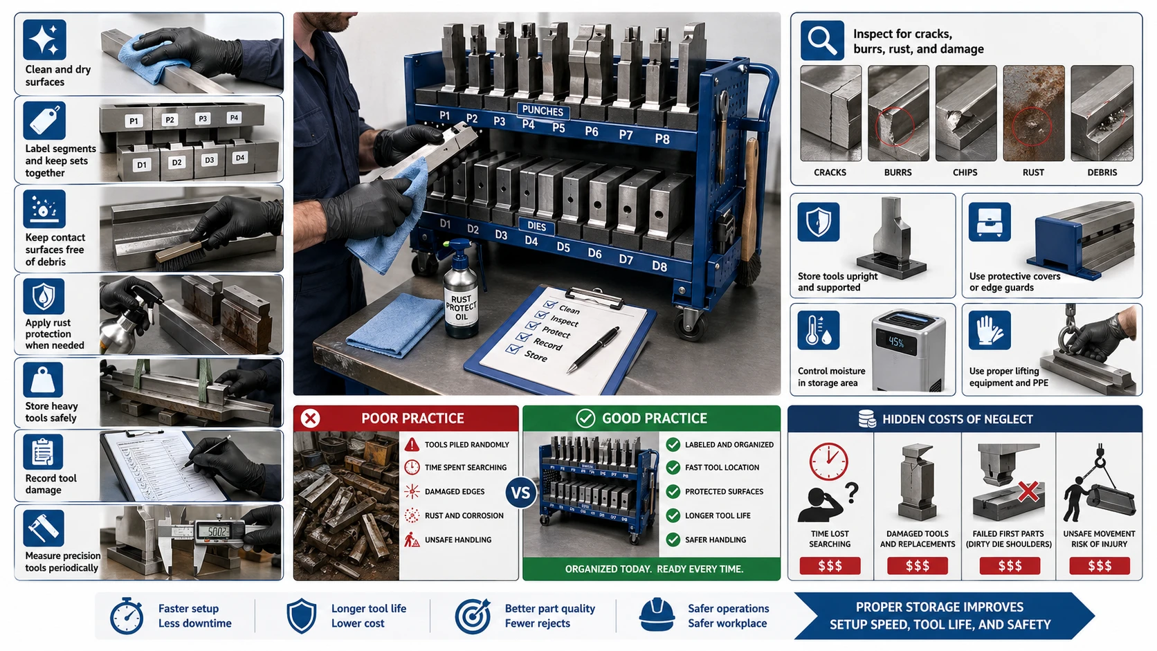
Tooling maintenance is often simple, but it is frequently ignored. Press brake tools should be clean, dry, labeled, inspected, and stored safely. The working surfaces should be protected from rust, dents, chips, and grinding damage. Precision-ground tools should not be thrown into a pile or mixed randomly. Segments should be kept in sets when required.
Poor storage creates hidden cost. Operators spend time searching for the right tool. Tools become damaged. Segments are lost. Tooling surfaces become rusty or dirty. The first part of the day may fail because the die shoulder has debris. Heavy tools are moved unsafely because there is no proper storage or loading support.
KRRASS offers tooling and tool storage solutions for safer storage, loading, unloading, and organization. Tool storage is not only a housekeeping matter. It supports setup speed, tool life, operator safety, and production discipline.
A practical maintenance routine should include daily cleaning of punch and die surfaces, inspection for cracks or burrs, checking segment labels, keeping contact surfaces clean, applying rust protection when necessary, and recording tool damage. For precision production, tools should also be measured periodically. If a tool is worn, the bend angle and radius may change even when the CNC program is unchanged.
Mistake 14: treating safety as separate from tooling
Press brake safety is often discussed in terms of light curtains, laser guards, two-hand controls, emergency stops, and guarding systems. These are important, but tooling also affects safety. A wrong die opening, overloaded tool, unsecured segment, heavy tool without lifting support, unstable short flange, or collision-prone bend sequence can create risk.
OSHA has long addressed power press brake guarding, and OSHA guidance recognizes ANSI B11.3 as a consensus standard for power press brake safeguarding. The current ANSI B11.3-2022 standard applies to machines classified as power press brakes that are designed for bending material. These references remind us that press brake operation is not only about accuracy; it is also about controlled risk.
Tooling-related safety practices include checking load ratings, using proper clamping, keeping hands away from the point of operation, using suitable guards and safety devices, supporting heavy sheets, using lifting aids for heavy tools, avoiding unstable setups, and training operators to understand the tool geometry. A press brake operator should know not only which button to press but also why the selected punch and die are safe for the job.
Small parts need special attention. If the part is too small to hold safely, the factory should consider alternative tooling, fixtures, backgauge support, front supports, or a different production method. Operators should not be forced to hold tiny flanges near the bending line because the tooling package was poorly selected.
Safety should be part of the quotation discussion. When a buyer requests high-speed production, frequent tool changes, heavy tooling, or complex bends, the machine configuration should include suitable safety arrangements and tooling handling methods. Productivity and safety should be designed together.
Mistake 15: ignoring the relationship between tooling and upstream processes
Press brake tooling does not work alone. The part usually starts with laser cutting, punching, shearing, or blank preparation. The blank size, hole position, notch design, grain direction, burr direction, and cutting accuracy all influence bending.
If a flat pattern is developed using one inside radius but production uses another, the final dimensions may shift. If holes are too close to the bend line, they may distort. If the burr side is placed incorrectly, it may affect surface quality or crack initiation. If the material grain direction is ignored, cracking risk may increase for certain materials and radii.
This is why tooling mistakes can create problems outside the press brake department. The laser cutting team may produce accurate blanks, but the bend result still fails because the tooling radius is different from the design assumption. The purchasing team may buy material with a different grade or tensile strength, and the previous bending program may no longer work. The quality team may measure dimensional errors without realizing that the root cause is tooling selection.
A strong production workflow connects engineering, cutting, bending, inspection, and purchasing. Tooling data should be available to the people who create flat patterns. Material substitutions should be reviewed by bending technicians. Critical parts should have approved tooling setups documented.
Mistake 16: buying special tooling too late
Special tooling can solve real production problems, but it should not be ordered at the last minute. Special punches, hemming tools, radius tools, offset tools, flattening tools, forming dies, and custom dies may require design review, manufacturing time, testing, and sometimes drawing modifications.
A common mistake is quoting a project based on standard tooling and then discovering that a special tool is required. This can delay delivery, reduce profit, and frustrate the customer. The better method is to identify special features early: hems, large radii, offsets, channels, louvers, deep boxes, return flanges, narrow U shapes, heavy plates, and cosmetic surfaces.
Not every difficult part needs special tooling. Sometimes a different bend sequence, segmented gooseneck punch, adjustable die, or wider machine opening can solve the issue. But the decision must be made through review, not guesswork.
For buyers, special tooling should be treated as part of the investment plan. If the factory will produce a high-volume part for several years, special tooling may pay back quickly through faster setup, lower scrap, and more stable quality. If the part is rare, outsourcing or redesign may be more economical. The commercial decision depends on volume, margin, delivery pressure, and strategic value.
Mistake 17: using tooling price as the only buying criterion
Low tooling price can be attractive, especially when a buyer is comparing several press brake quotations. However, tooling quality affects accuracy, life, safety, and setup time. A cheap tool that wears quickly, marks parts, or does not align properly can cost more than a higher-quality tool.
Important tooling quality factors include material, heat treatment, hardness, grinding accuracy, straightness, load rating, surface finish, segmentation accuracy, marking, and compatibility with the clamping system. For precision-ground tooling, tolerances and repeatability are especially important. For heavy-duty tooling, strength and load rating are critical. For cosmetic bending, die shoulder finish and protective options matter.
A better purchase comparison should include total cost of ownership. Ask how often the tool will be used, how much scrap it could prevent, how much setup time it could save, how long it should last, and whether it supports future products. Tooling is not only a purchase cost; it is a production asset.
This is especially true for factories moving from low-mix production to high-mix production. As product variety increases, tooling flexibility becomes more valuable. Segmented tooling, fast clamping, organized storage, and CNC tool libraries may cost more at purchase, but they help the factory respond faster to orders.
A practical tooling selection workflow for buyers
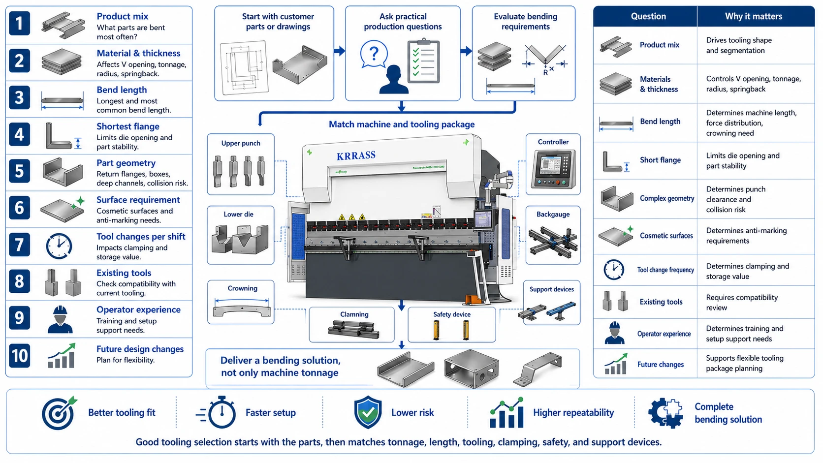
A practical workflow helps prevent most tooling mistakes. It does not require every buyer to become a tooling engineer, but it does require the right information.
| Step | Question to answer | Why it matters |
|---|---|---|
| 1 | What products will the factory bend most often? | Product mix drives tooling shape and segmentation |
| 2 | What materials and thicknesses are common? | Controls V opening, tonnage, radius, and springback |
| 3 | What is the longest and most common bend length? | Determines machine length, force distribution, and crowning need |
| 4 | What is the shortest flange? | Limits die opening and affects part stability |
| 5 | Are there return flanges, boxes, or deep channels? | Determines punch clearance and collision risk |
| 6 | Are surfaces cosmetic? | Determines anti-marking requirements |
| 7 | How many tool changes happen per shift? | Determines clamping and storage value |
| 8 | Are existing tools available? | Requires compatibility review |
| 9 | Are operators experienced? | Determines training, controller, and setup support needs |
| 10 | Will product designs change in the future? | Supports flexible tooling package planning |
When we support a press brake inquiry, we prefer to start with the customer's parts. If drawings are available, they are the best starting point. If drawings are not available, we ask practical questions about product categories, material thickness, bend length, flange length, and surface requirements. Then we match the bending requirement to machine tonnage, length, controller, backgauge, crowning, tooling, clamping, safety, and optional support devices.
This approach avoids a common sales problem: recommending a machine based only on tonnage. Tonnage matters, but it is not enough. A factory needs a bending solution, not only a machine body.
Recommended tooling package logic by factory type
Different factories need different tooling packages. The following table gives practical examples. It is not a fixed quotation standard, but it helps buyers think clearly.
| Factory type | Common products | Tooling priority | Suggested direction |
|---|---|---|---|
| Electrical cabinet factory | Doors, panels, boxes, mounting plates | Segmented tooling and gooseneck clearance | Precision segmented punch/die set, quick clamping, common V openings |
| Stainless steel kitchen equipment factory | Tables, sinks, covers, food equipment panels | Surface protection and clean bends | Anti-marking dies or films, polished tool surfaces, controlled radius |
| HVAC and duct factory | Duct sections, covers, light-gauge sheet | Speed and simple repeatability | Common V dies, standard punches, backgauge support, efficient setup |
| Elevator or architectural panel factory | Long cosmetic panels | Angle consistency and surface quality | Crowning, long tools, anti-marking solutions, careful handling |
| Heavy bracket factory | Thick steel brackets and structural parts | Tonnage and tool load | Heavy-duty dies, larger V openings, high-rated punches, force review |
| Job shop | Mixed parts and short batches | Flexibility and fast changeover | Segmented tooling, multi-V dies, quick clamping, organized storage |
| Automotive or appliance supplier | Repeat parts with strict tolerance | Repeatability and documented process | Precision-ground tooling, CNC tool library, inspection routine |
This table also shows why asking for a generic tooling package can be risky. A cabinet factory and a heavy bracket factory may both buy a CNC press brake, but their tooling needs are very different.
How to avoid tooling mistakes before placing an order
The best time to avoid a tooling mistake is before purchase. Once the machine is installed and production pressure begins, every correction becomes more expensive. Use the following checklist before finalizing a press brake and tooling order.
| RFQ item | Information to provide | Risk if missing |
|---|---|---|
| Material list | Grade, thickness, tensile strength if known | Wrong tonnage and radius assumptions |
| Part drawings | DXF, STEP, PDF, or sample photos | Hidden collision and flange problems |
| Surface requirement | Painted, brushed, polished, coated, or unfinished | Tooling may mark cosmetic parts |
| Minimum flange | Shortest flange by thickness | Die opening may be too wide |
| Bend length | Maximum and common bend lengths | Wrong machine length or tonnage planning |
| Bend angle and radius | Required angle and inside radius | Wrong punch/die combination |
| Production volume | Daily/monthly output or batch size | Wrong clamping and automation level |
| Existing tooling | Tool type, tang, height, and condition | Compatibility problems |
| Operator skill | Beginner, intermediate, experienced | Training and controller needs |
| Future products | Planned thickness or product changes | Tooling package may be too narrow |
A buyer does not need to know every answer perfectly. Even approximate information is better than none. For example, saying "we mostly bend 1.5 mm and 2 mm stainless steel cabinet panels with visible surfaces" is much more useful than saying "we need a 100-ton press brake." The first statement helps us discuss V openings, surface protection, backgauge, segmented tooling, and clamping. The second statement only gives a machine size.
Practical rules that help, and where they can mislead
Rules of thumb are useful when used correctly. They help buyers and operators make quick estimates. But they become dangerous when treated as absolute standards.
The eight-times-thickness rule for V opening is a good starting point for many mild steel air-bending jobs, but it may not fit stainless steel, aluminum, high-strength steel, short flanges, cosmetic surfaces, or drawings with a specified radius. The 16-percent-of-V relationship for mild steel radius helps estimate inside radius, but it is not a guarantee for every material. The 70-percent-of-V minimum flange estimate helps detect risk, but actual tooling geometry and part shape still matter.
| Rule of thumb | Useful meaning | Main limitation |
|---|---|---|
| V opening ≈ 8 × material thickness | Quick starting point for air bending mild steel | Not universal for all materials, radii, or flanges |
| Inside radius ≈ 16% of V for mild steel air bending | Helps estimate radius from die opening | Material and process change the result |
| Minimum flange ≈ 70% of V | Helps detect short-flange risk | Depends on die geometry and bend conditions |
| Wider V reduces tonnage | Helps reduce force and marking | Increases radius and minimum flange length |
| Narrower V supports shorter flanges | Helps with small parts | Increases tonnage and marking risk |
| Gooseneck punch improves clearance | Helps boxes and return flanges | Has load limits and height implications |
The right approach is to use rules of thumb for early planning and then verify with drawings, material data, tooling ratings, and production testing.
How KRRASS supports tooling decisions
KRRASS is not only a press brake supplier. We manufacture and configure sheet metal forming equipment for real production needs, including press brakes, hydraulic shearing machines, fiber laser cutting machines, ironworker machines, and related tooling options. For press brake buyers, tooling is part of our recommendation process.
When a customer discusses a new machine with us, we review the production picture. We ask about material, thickness, bend length, flange length, product type, surface requirement, production volume, and future development. Then we recommend a press brake configuration and tooling plan. Depending on the work, that may include standard punches and dies, segmented tooling, gooseneck punches, multi-V dies, adjustable dies, tooling cabinets, quick clamping, hydraulic clamping, bending followers, crowning systems, or CNC control options.
Our online resources can help buyers prepare before contacting us. The press brake tooling chart explains how tooling relates to material, thickness, bending angle, machine compatibility, and forming results. The fundamentals of press brake tooling article explains punch and die interaction, bend radius, air bending, bottoming, tool selection, and stage bending in a beginner-friendly way. The press brake tools guide introduces the role of dies, punches, holders, adapters, and custom tooling. These pages help buyers understand why tooling should be discussed before the final machine configuration is fixed.
For more advanced productivity planning, buyers can also review KRRASS options such as tooling and tool storage solutions, tooling clamping systems, and WILA Smart Tooling. These options are especially valuable for factories that change tools frequently, handle heavy tooling, require high repeatability, or want a cleaner tool management workflow.
Final recommendations
Press brake tooling mistakes are avoidable when buyers treat tooling as part of the bending system. The punch and die are not small accessories added after the machine is chosen. They determine bend radius, flange stability, tonnage, surface quality, collision clearance, setup time, safety, and long-term flexibility.
The most important recommendation is to start from the part. Review drawings, materials, thicknesses, bend lengths, flanges, radii, volumes, and surface requirements. Then choose the bending method, die openings, punch profiles, segmented tooling, clamping system, crowning requirements, and storage plan. This approach leads to better quotations, fewer surprises, and more reliable production.
The second recommendation is to respect trade-offs. A wider die may reduce tonnage and marking, but it increases radius and minimum flange length. A narrower die may help short flanges, but it increases force and tool load. A gooseneck punch may solve collision, but it must be checked for load capacity. Hydraulic clamping may cost more initially, but it can save time in high-mix production. Every tooling decision has a production consequence.
The third recommendation is to verify tooling data. Check tool ratings, material behavior, bend force, minimum flange, radius, compatibility, and safety. Do not rely only on memory or catalog pictures. Use rules of thumb as starting points, then confirm with real requirements.
Finally, choose a supplier that can discuss both machine configuration and tooling logic. At KRRASS, we see press brake tooling as a core part of the bending solution. Whether you are building a new sheet metal factory, upgrading an older press brake, expanding into stainless steel products, or improving high-mix production, a correct tooling plan will help your machine produce better parts, faster setups, lower scrap, and stronger long-term value.