The Press Brake is a vital piece of equipment in the field of metal sheet processing, and its performance and selection play a key role in determining product accuracy, production efficiency, and even the overall processing capabilities of a business. Whether it’s the simple bending of small hardware parts or the precise forming of complex aerospace components, whether it’s large-scale standardized production or flexible manufacturing of small batches and multiple varieties, each application brings unique demands in terms of bending force, synchronization precision, automation level, and safety performance.
Choosing the right Press Brake means more than just meeting today’s production needs — such as handling materials ranging from ultra-thin 0.1mm aluminum foil to thick, high-strength steel plates over several tens of millimeters, achieving angle precision from ±1° for general parts to ±0.1° for high-precision components, and managing workpieces from basic right-angle bends to complex multi-step shaping. It also means planning ahead for future growth and process improvements — like whether the machine can integrate with automated production lines or support the bending requirements of new materials.
Today’s market offers a wide range of Press Brake options — from economical torsion shaft models to highly accurate electro-hydraulic servo machines, and even intelligent CNC bending centers. Brands and configurations vary greatly, from core CNC systems (such as international names like Delem and domestic leaders like Estouch) to drive types and safety features. Each decision can influence both the initial investment and long-term operating costs.
This guide is designed to help you understand the key factors in selecting the right Press Brake. By offering a comprehensive overview and practical insights, it aims to provide a clear decision-making framework for businesses of all sizes and industries, helping you find the ideal match among the many available options. Our goal is to ensure that your chosen equipment becomes a reliable foundation for improved productivity and superior product quality.

Table of Contents
I.Introduction to Press Brake
A Press Brake is a specialized industrial machine designed to bend and shape metal sheets with precision and reliability. Its main purpose is to apply controlled pressure through specific molds and power systems, allowing the metal sheet to undergo plastic deformation at a pre-set location. This process enables the creation of the desired angles, curves, and complex geometric forms.
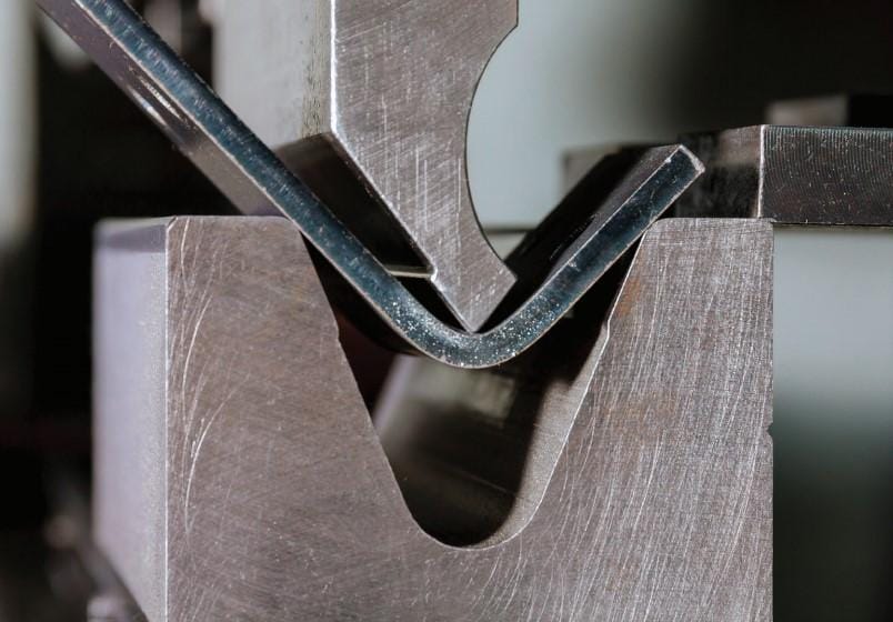
From a functional perspective, the basic operation of a Press Brake is quite straightforward: the metal sheet is placed on the workbench and securely positioned using a locating device. Then, the slider (or upper mold) moves downward under the power drive and works together with the lower mold on the workbench to apply pressure. This pressure forces the sheet to bend along the contour of the mold. To ensure high-quality results, the system must deliver enough force to overcome the metal’s resistance while maintaining precise control over the bending angle and dimensions.
Structurally, a Press Brake typically includes a sturdy frame, a worktable, a slider, a hydraulic or mechanical drive system, and a numerical control (NC) system. Thanks to the integration of advanced NC systems, modern Press Brakes can perform automated operations with ease. Operators simply input the required bending parameters, and the machine intelligently controls the slider’s movement, speed, and pressure to ensure every bend meets the design specifications. This makes it especially well-suited for both high-volume production and the fabrication of intricate shapes.
At its heart, the Press Brake is all about achieving precise bending. Whether powered by hydraulics, mechanical transmission, or electro-hydraulic servo control, the ultimate goal remains the same — to shape metal sheets exactly as intended. The applications of Press Brakes are incredibly diverse. In the automotive industry, they are essential for forming body frames and chassis components; in construction machinery, they help shape mechanical arms and support structures. They are also widely used in home appliance manufacturing, shipbuilding, and aerospace, where they provide reliable support for large-scale, high-precision metal production. As a key tool in metal fabrication, the Press Brake plays a vital role in transforming flat sheets into three-dimensional components.
As industrial technology continues to evolve, so too does the Press Brake — becoming more precise, more efficient, and increasingly intelligent. It is a dedicated machine that uses mechanical force to reshape metal sheets, enabling the transformation from flat to three-dimensional and from simple to complex structures. In modern manufacturing, the Press Brake stands as a cornerstone of metal forming, and its continuous innovation continues to drive progress across a wide range of industries.
II.How a Press Brake Works
The core working principle of the Press Brake is to drive the actuator through the power system, and in combination with the mold, apply directional pressure to the metal sheet, causing it to undergo plastic deformation, thereby completing the bending processing. This is a process with multiple precise steps of coordination, from sheet positioning to final formation, each step relying on the collaborative operation of the various components of the Press Brake.
After the Press Brake is started, the operator needs to place the metal sheet to be processed on the working table of the Press Brake. The working table of the Press Brake is not merely a simple supporting surface. The rear clamping device equipped on it is driven by a servo motor and can be precisely adjusted in the front and rear positions through the numerical control system. The error is usually controlled within 0.1 millimeters. When the metal sheet is placed on the working table, the operator can input parameters through the control panel of the Press Brake according to the processing requirements, allowing the rear clamping device to automatically move to the designated position and press the end of the sheet against the rear clamping device, thereby determining the starting point of the bending.
Subsequently, the power system of the Press Brake began to operate. Different types of Press Brakes have different power transmission methods. In hydraulic Press Brakes, the hydraulic oil in the tank passes through the filter and enters the hydraulic pump. Under the drive of the motor, the hydraulic pump converts the low-pressure oil into high-pressure oil. After the pressure is regulated by the relief valve, it is controlled by the electromagnetic directional valve to enter the non-piston chamber or the piston chamber of the hydraulic cylinder. When the high-pressure oil enters the non-piston chamber, the piston drives the piston rod to push the slider downward; while when the high-pressure oil enters the piston chamber, the slider moves upward in the return journey. Throughout this process, the pressure relay of the Press Brake will monitor the system pressure in real time to ensure that the pressure is stable within the preset range.
If it is a mechanical-driven Press Brake, it is driven by a motor that rotates gears and crankshafts, thereby moving the slider to perform the downward action. During this process, the control system of the Press Brake will precisely control the downward speed and pressure of the slider based on preset parameters. When the slider moves towards the sheet placed on the workbench, the upper die and the fixed lower die on the workbench start to cooperate, applying pressure to the sheet. At this point, the pressure applied by the Press Brake exceeds the yield limit of the metal sheet, forcing the sheet to bend and deform along the contour of the mold under the action of the upper and lower dies. As the slider continues to descend, the bending angle of the sheet gradually reaches the preset requirements. The control system of the Press Brake will promptly issue an instruction to stop the slider's movement and start the return journey, completing one bending cycle.
Throughout this process, the core of the Press Brake lies in achieving precise pressure application and precise motion control through power transmission. Whether it is the pressure size, the slider's travel distance, or the bending speed, all are uniformly regulated by the control system of the Press Brake to ensure that each bending can meet the design standards. It can be said that the working principle of the Press Brake is a perfect combination of mechanical force, control system, and molds, ultimately achieving efficient and precise bending of metal sheets.
Furthermore, the deflection compensation device of the Press Brake is also an important part for ensuring the accuracy of the bending process. Due to the slight deformation that occurs when the slider and the worktable are subjected to force, the Press Brake will set up a wedge-shaped compensation mechanism or a hydraulic compensation cylinder under the worktable. Based on the magnitude of the bending force, it will automatically adjust the curvature of the worktable to counteract the deformation effect, ensuring that the bending angle of the sheet material is consistent throughout its width direction.
In summary, the specific working principle of the Press Brake is that the positioning device ensures precise positioning, the power system provides stable power, the mold realizes shape shaping, and together with the real-time control of the control system and the accuracy guarantee of the compensation device, it achieves efficient and precise bending of metal sheets.
III.Press Brake Category
The types of Press Brakes include mechanical Press Brakes, hydraulic Press Brakes, electro-hydraulic servo Press Brakes, and pure electric Press Brakes, among others. Each of them has distinct differences in working principles, applicable scenarios, and performance characteristics. The following are the common categories:
Mechanicl Press Brake
Working principle: The flywheel is driven by the motor, and then the mechanical transmission structures such as gears and crankshafts are used to drive the slider to move up and down, achieving bending.
Features: Simple structure, low cost, easy maintenance; The stroke and speed of the slider are limited, and the bending accuracy is moderate; Suitable for small and medium batch, low precision simple bending operations (such as thin plates, low-carbon steel).
Limitations: The energy output is relatively fixed and difficult to adapt to complex processes, gradually being replaced by hydraulic Press Brake.

Hydraulic Press Brake
Working principle: Powered by a hydraulic pump, the hydraulic cylinder (single cylinder or double cylinder) drives the slider to move, and the pressure of the hydraulic oil controls the bending force and speed.
Classification: Single-cylinder hydraulic Press Brake: Compact structure, suitable for small equipment; Double-cylinder hydraulic Press Brake: The left and right cylinders are synchronized controlled, with higher precision, and is the most widely used.
Features: Large bending force (up to several thousand tons), adjustable speed, precise stroke control; Capable of multi-stage bending and processing of complex angles, suitable for thick plates, high-strength steel, etc.; The hydraulic system has overload protection, high safety, and is the current mainstream model.

electro-hydraulic servo Press Brakes
Working Principle: Based on a hydraulic press brake, a servo motor and closed-loop control system (such as a linear scale and encoder) are added to provide real-time feedback on the slide position and precisely control the cylinder pressure.
Features: Extremely high synchronization accuracy (±0.01mm), with angular error controlled within ±0.1°; fast response speed, suitable for high-precision, complex bending (such as automotive parts and precision sheet metal); low energy consumption (the servo motor outputs power on demand), but relatively high cost.
Electric Press Brake
The working principle of the Electric Press Brake: The Electric Press Brake directly drives the mechanical transmission structure (such as ball screws, synchronous belts, gearboxes, etc.) through a servo motor, causing the slider to move up and down to achieve sheet metal bending. The specific process is as follows:
Power output: Power is provided by a high-performance servo motor, and the motor's rotational speed and torque can be precisely controlled by the numerical control system.
Motion conversion: The rotational motion of the motor is converted into linear motion of the slider through ball screws (or gear racks), driving the upper die to press down.
Closed-loop control: Sensors such as grating scales and encoders are equipped to provide real-time feedback on the slider's position, speed, and pressure. The numerical control system dynamically adjusts the motor output based on preset parameters (such as bending angle, depth) to ensure motion accuracy.
Bending completion: After the slider presses down to the preset position, the motor runs in reverse to drive the slider to rise, completing one bending cycle.

Core Features of Electric Press Brake
No reliance on hydraulic oil: No need for hydraulic pumps, cylinders, pipes, etc. of hydraulic components, avoiding environmental pollution caused by hydraulic oil leakage, and eliminating maintenance procedures such as hydraulic oil replacement and filtration.
Low energy consumption: The servo motor only outputs power when working, and the energy consumption in standby mode is extremely low. Compared with hydraulic Press Brake, the energy consumption is reduced by 30%-60% (especially suitable for batch production scenarios).
Precise position control: The slider positioning accuracy can reach ±0.01mm, and the angle error can be controlled within ±0.1°, suitable for precision sheet metal parts (such as electronic equipment casings, medical device components).
Fast response speed: Motor drive does not have the "lag effect" of the hydraulic system, the slider acceleration, deceleration, and direction change are more rapid, and the bending efficiency is improved by 10%-20% compared to hydraulic machines.
Strong anti-interference ability: There is no pressure fluctuation problem of the hydraulic system, the bending consistency is better under the same parameters, especially suitable for multi-batch small-batch production.
Compact mechanical structure: Without large components such as hydraulic stations, the equipment has a smaller占地面积 and is more flexible to install (can be adapted to narrow workshops).
Low maintenance cost: The core components are servo motors and ball screws, the failure rate is much lower than that of the hydraulic system (such as oil cylinder leakage, hydraulic valve jamming, etc.), and daily maintenance only requires regular inspection of the lubrication of transmission components and sensor calibration.
IV.How to use the Press Brake(Take CNC Press Brake as an example)
- Safety Inspection: Ensure that the emergency stop button, guardrails, laser guards, etc. are in good condition. Test the emergency stop function before starting the machine. Check the power voltage and grounding. For hydraulic Press Brakes, confirm the hydraulic oil level and temperature (normal range: 15-55℃). Check if the servo motor connection lines are loose.
- Preparation of Workpieces and Dies: Based on the material type (such as carbon steel, stainless steel, aluminum) and thickness of the sheet, select matching upper dies (such as sharp-edge dies, circular arc dies) and lower dies (the V-shaped groove width should be 6-8 times the sheet thickness to avoid cracking). Clean the oil stains and impurities on the die surface, check if there are cracks or wear on the die, and replace or repair if necessary. Measure the sheet dimensions to ensure that the flatness meets the requirements (sheets with severe deformation need to be leveled first to avoid uneven force during bending).
- Parameter Setting: Input the bending length, angle, sheet thickness, etc. through the CNC system. The system automatically calculates the bending depth (or manually fine-tunes), and pre-plays the bending path (some models support 3D simulation). Test bend 1-2 sample pieces, measure the actual angle and size, and correct the parameters through the "angle compensation" function (consider material rebound, such as the rebound rate of stainless steel is higher than that of low-carbon steel).
- Clamping the Workpiece: Place the sheet steadily on the lower die, align with the positioning ruler, ensure that the bending line coincides with the center line of the die, and fix it with fixtures if necessary (to prevent sliding).
- Start Running: Confirm that the operator's hands are away from the dangerous area (for hydraulic Press Brakes, both hands need to press the start button). Start the equipment, observe if the slider descends smoothly and if there are any abnormal noises.
- Completion and Inspection: After the slider rises, remove the workpiece, check the bending angle, straight edge length, and whether there are marks or deformations on the surface. If不合格, adjust the parameters.
- Do not bend sheets exceeding the maximum bending force (tonnage) or thickness of the equipment to avoid damaging the die or body.
- Do not place non-bending workpieces (such as tools, waste materials) between the dies to prevent crushing and causing equipment jamming.
- Hydraulic Press Brakes are prohibited from running for a long time without load (to avoid overheating of the hydraulic system); Electric Press Brakes are prohibited from frequently stopping (to protect the servo motor).
V.Press Brake Maintenance Method
Daily maintenance (daily/per shift)
Cleaning: Clean the iron filings and oil stains on the workbench and mold surface, wipe the equipment shell, and keep the ventilation holes unobstructed (especially the motor ventilation holes of ElectricPress Brake).
Lubrication: Add lubricating oil to the moving parts such as slider guide rails and lower mold positioning pins according to the instructions (hydraulic Press Brake requires the use of special hydraulic oil, and ElectricPress Brake should focus on lubricating the ball screw).
Hydraulic system: Check for any leakage in the oil pipes, whether the pressure on the hydraulic gauge is stable, and replace the sealing parts in time if there is oil leakage.
Electrical system: Check if the cable connectors are loose, if the buttons and indicator lights are normal, and if the grounding is reliable.
Mechanical components: Confirm whether the mold fixing bolts are tightened, and whether the gap between the slider and the guide rail is too large (normally it should be ≤ 0.03mm).
Regular maintenance (weekly/monthly)
weekly:
Hydraulic Press Brake: Check the oil level in the oil tank. If it is below the lower limit, replenish it promptly (with the same type of hydraulic oil) and clean the oil suction filter element.
Electric Press Brake: Check the temperature of the servo motor (it should not exceed 60℃ during operation), and clean the dust on the encoder and grating scale (wipe with a dust-free cloth).
All models: Test the safety protection devices (such as whether the guard device triggers and immediately stops the machine).
per month:
Calibration of bending accuracy: Use a dial indicator to measure the repetitive positioning error of the slider. When it exceeds the limit, it can be corrected through the CNC system or mechanical adjustment (such as adjusting the gap of the guide rail).
Hydraulic Press Brake: Check the pressure of the hydraulic pump, and adjust the relief valve if necessary; replace the oil filter element, and conduct regular (every 6 months) sampling tests to detect the contamination degree of the hydraulic oil. If it exceeds the limit, replace all of it.
Electric Press Brake: Check the preload force of the ball screw. If there is looseness or abnormal noise, tighten or replace the nut in time.
Long-term maintenance (annual/major overhaul)
Comprehensive disassembly and inspection of key components: such as the hydraulic cylinders and pistons of the Press Brake (check for wear, replace the seals); the servo motor bearings of the Electric Press Brake (check for noise and temperature rise, replace if necessary).
Replacement of aging components: such as cables, contactors, limit switches and other wear-prone parts to ensure the stability of the electrical system.
Re-calibration of the CNC system: cooperate with the technical staff of the equipment manufacturer to perform high-precision calibration of the angle sensors and position feedback systems to ensure the accuracy of the bending parameters.
Special maintenance considerations
Idle maintenance: When the equipment is out of use for more than 1 month, the hydraulic oil in the system must be emptied (filtered and sealed for storage). The Electric Press Brake needs to be powered off and covered with a dust cover. The molds should be coated with anti-rust oil and stored separately.
Fault handling: In case of abnormalities (such as excessive noise, sudden drop in accuracy, oil leakage), stop the machine immediately. Do not attempt to force it to run. Contact professional maintenance personnel for troubleshooting (for hydraulic system faults, avoid disassembling the hydraulic valves by yourself to prevent contamination).
By following standard operations and conducting regular maintenance, the service life of the Press Brake can be extended by more than 30%, while effectively reducing the failure rate and ensuring production efficiency and processing quality. The maintenance details for different types (hydraulic, Electric, mechanical) of Press Brakes may vary slightly, and must be strictly adhered to the specific requirements of the equipment manual.
VI.Common Faults and Solutions for Press Brake
During long-term use, the Press Brake may encounter various faults due to mechanical wear, aging of the hydraulic system, and wear of electrical components. The following lists common faults and their solutions categorized by mechanical system, hydraulic system, and electrical system:
1.The slider is not running smoothly (there is a jam or abnormal noise)
Possible causes: Insufficient lubrication of the slider guide rail or iron filings, impurities getting stuck. Excessive guide rail clearance (resulting from long-term wear). Loose or worn transmission gears / chains (for mechanical Press Brake).
Elimination methods: Clean the surface of the guide rail, add dedicated lubricating oil (such as lithium-based grease). Adjust the clearance of the guide rail: Use the adjusting bolts on the side of the guide rail to control the clearance within 0.02-0.03mm (using a feeler gauge for detection). Inspect the gears / chains, tighten loose components, replace new parts when severely worn.
2.The mold is loose or not positioned correctly after installation
Possible causes: The fixing bolts of the mold were not tightened or the threads were stripped. The positioning groove of the lower mold was worn out, resulting in an excessive gap with the mold. The positioning ruler was loose or deformed.
Exclusion methods: Replace the stripped bolts, and tighten them using a torque wrench according to the specified torque (usually 30-50 N·m). Repair the positioning groove: Minor wear can be repaired by welding and then re-milling; severe cases require replacement of the lower mold base.
Calibrate the positioning ruler: If it is loose, tighten the fixing bolts; if it is deformed, disassemble it for straightening or replacement.
3.The angle deviation of the workpiece after bending is large (the angles on both sides are inconsistent)
Possible causes: The travel distances of the left and right sliders are not consistent (poor synchronization). The two sides of the V-shaped groove of the lower die are worn unevenly. The workpiece is not aligned with the center line during positioning.
Elimination methods: Adjust the synchronization mechanism: For hydraulic Press Brake, adjust the flow valves of the oil cylinders on both sides; for CNC Press Brake, calibrate using the "synchronization compensation" function of the system. Replace the lower die or use it upside down (utilizing the un-worn V-shaped groove). Re-position the workpiece to ensure that the bending line coincides with the center line of the die. If necessary, use positioning fixtures.
4.Insufficient or no pressure in the hydraulic system
Possible causes: Insufficient oil suction by the hydraulic pump (low oil level in the tank, blocked oil suction filter). Faulty overflow valve (valve core stuck or pressure regulating spring broken). Wear of the hydraulic pump (severe internal leakage) or incorrect motor rotation direction.
Exclusion methods: Refill the hydraulic oil to the specified level (the oil level should be higher than the oil suction port), replace the blocked oil suction filter. Disassemble the overflow valve, clean the impurities on the valve core, replace the broken spring; re-adjust the pressure to the rated value (refer to the equipment manual, usually 10-20 MPa). Check the oil flow direction at the inlet and outlet of the hydraulic pump, confirm the correct motor rotation direction; replace the hydraulic pump if the pump body is worn.
5.Oil cylinder leakage (piston rod or cylinder joint)
Possible causes: The piston rod seal is aging or damaged (common in frequently used equipment). The connecting bolts between the cylinder body and the end cover are loose, causing uneven pressure on the sealing ring. The surface of the piston rod is scratched (caused by iron filings or hard objects colliding).
Exclusion methods: Replace the seal: Remove the oil cylinder, take out the old seal ring (pay attention to model matching, such as polyurethane or nitrile rubber), install the new part and apply hydraulic oil for lubrication. Tighten the end cover bolts evenly (tighten in a diagonal order). Minor scratches can be polished and polished the surface of the piston rod; in severe cases, the piston rod needs to be replaced.
6.The slider returns slowly or cannot return
Possible causes: Backflow oil passage blockage (valve core stuck). Directional valve failure (electromagnet not engaged or valve core worn). High viscosity of hydraulic oil (low oil temperature, such as in winter).
Exclusion methods: Disassemble the directional valve, clean the debris from the valve core, and ensure that the valve core can move freely. Check the wiring of the directional valve electromagnet; if there is no electricity, repair the circuit; if the valve core is worn, replace the directional valve. Start the equipment for a 10-15 minute idle run, raise the oil temperature to above 15℃; or replace with low-viscosity hydraulic oil (such as 32# hydraulic oil in winter).
7.The device will not start (it is plugged in but not responding)
Possible causes: The emergency stop button has not been reset or is damaged. The power circuit breaker has tripped (overload or short circuit). The control circuit contactor is faulty (coil burnt or contacts oxidized).
Troubleshooting: Check the emergency stop button and rotate it to reset it; if damaged, replace it with a new one. Check for the short circuit (such as a damaged motor cable), repair it, and reset the circuit breaker. Measure the contactor coil voltage. If there is no voltage, check the control circuit; if the coil is burned or the contacts are oxidized, replace the contactor.
8.The CNC system shows abnormal conditions (such as garbled characters, no display, or loss of parameters)
Possible causes: Unstable system power voltage or poor grounding. Loose display connection cable or damaged screen. System program error or storage chip failure.
Troubleshooting methods: Check the power voltage (should be 220V ± 10%), reconnect the grounding lines (grounding resistance ≤ 4Ω). Plug and unplug the display connection cable, clean the interface dust; if the screen is damaged, contact the manufacturer for replacement. Restart the system and reload the backup parameters; if the storage chip is faulty, replace the motherboard or contact the manufacturer for repair.
9.Failure of the protective device (such as the protective device triggering but the equipment not stopping operation)
Possible causes: Safety sensors (such as infrared barriers or limit switches) are misaligned or damaged. Safety circuit wiring is loose or disconnected. The control system is not recognizing the safety signal (program error).
Troubleshooting: Calibrate the sensor position and test sensitivity. If damaged, replace the sensor with a similar model. Check the safety circuit wiring, re-tighten any loose terminals, and repair any broken wires. Reset the control system program or contact the manufacturer's technicians to debug the safety logic.
10.General troubleshooting notes
Shutdown operation: Before troubleshooting any faults, the main power supply of the equipment must be cut off. For the hydraulic Press Brake, the system pressure also needs to be released (through the relief valve) to prevent accidental startup or hydraulic oil spraying.
Professional maintenance: When complex operations such as disassembling hydraulic valves and debugging the CNC system are involved, they should be carried out by professional technicians to avoid secondary damage caused by self-maintenance (such as contamination of the hydraulic system, circuit short-circuiting).
Recording and backup: Regularly record the operating parameters of the equipment (such as hydraulic pressure, motor temperature), and back up the CNC system parameters to facilitate quick comparison and troubleshooting during faults.
By promptly identifying and resolving faults, the downtime of the equipment can be reduced, ensuring the stable operation of the Press Brake. In daily maintenance, if any minor abnormalities (such as slight oil leakage, abnormal noise) are found, they should be dealt with as soon as possible to avoid small problems escalating into major issues.
VII.What are the differences between different types of Press Brakes?
Hydraulic Press Brake, mechanical Press Brake, electro-hydraulic servo Press Brake, and Electric Press Brake are the four most representative types of Press Brakes. The core differences lie in the power source, transmission method, performance indicators, and application scenarios. The following provides a comparison from key dimensions and explains the core characteristics of each type:
| Comparison Dimension | Mechanical Press Brake | Hydraulic Press Brake | Electro-Hydraulic Servo Press Brake | Electric Press Brake |
| Power Source | Ordinary asynchronous motor (drives mechanical structure) | Ordinary asynchronous motor (driving hydraulic pump) | Servo motor (driving hydraulic pump with closed-loop control) | Servo motor (direct drive actuator, no hydraulic components) |
| Transmission Core | Mechanical structures such as gears, crankshafts, and connecting rods (rigid transmission) | Hydraulic pump, cylinder, hydraulic oil (hydraulic transmission) | Servo motor + hydraulic pump + cylinder ("electro-hydraulic closed-loop control") | Servo motor + ball screw / timing belt (mechanical transmission + electronic control) |
| Bending Accuracy | Medium (±0.3°-±0.5°), prone to mechanical play leading to misalignment | Higher (±0.1°~±0.2°), depends on synchronous compensation system | Extremely high (±0.05°~±0.1°), servo closed loop real-time correction | Extremely high (±0.03°~±0.05°), no transmission gap, extremely fast response |
| Tonnage Range | Small-Medium (typically ≤500 tons), limited by mechanical strength | Medium - Extra Large (50~5000 tons, customizable extra large models) | Medium - Extra Large (100~6000 tons, supporting large tonnage and high precision) | Small - Medium (30~300 tons, currently there are few large-tonnage models) |
| Operating Speed | Fast (high mechanical transmission efficiency), but limited return | Medium (fast forward/working forward/return speeds are balanced, limited by the hydraulic oil flow rate) | Fast (servo motor speed adjustment according to demand, working speed is 30% higher than ordinary hydraulic press) | Extremely fast (servo motor direct drive, acceleration/deceleration response 50% faster than hydraulic press) |
| Energy Consumption | speed (requires reverse transmission) | High (the hydraulic pump runs at a constant speed, resulting in high energy loss, with no-load energy consumption accounting for 60%) | Medium - Low (Servo motor outputs power on demand, energy consumption is 40% lower than ordinary hydraulic presses) | Low (the servo motor only runs when working, and the energy consumption is 30%~50% of the hydraulic press) |
| Environmental Performance | Medium (motor continuously running, high no-load energy consumption) | There is a risk of oil leakage (hydraulic oil contamination), and the noise level is moderate (75-85dB) | Low risk of oil leakage (servo control reduces no-load operation), low noise (70~80dB) | No oil, low noise (65~75dB), zero pollution |
| Maintenance Cost | No oil pollution, but high mechanical noise (85-90dB) | High (regular replacement of hydraulic oil, filter element, and seals is required, and frequent oil leak repairs are required) | Medium (hydraulic system maintenance + servo motor maintenance, the failure rate is lower than that of ordinary hydraulic presses) | Low (no hydraulic system, only motor and screw need to be maintained, long component life) |
| Core Advantages | Medium (gears/crankshafts require regular lubrication, high replacement cost due to wear) | Large tonnage capacity, suitable for thick plate bending | It combines large tonnage with high precision, fast response, and energy consumption is better than ordinary hydraulic presses. | High precision, low energy consumption, environmental protection, suitable for precision thin plate processing |
| Core Limitations | Simple structure, low cost, high speed Limited tonnage, low precision, prone to mechanical damage due to overload | Low upper limit of accuracy, high energy consumption, oil leakage pollution | There is still a need for hydraulic system maintenance, and the cost is higher than that of ordinary hydraulic presses | Weak large tonnage capacity, not suitable for bending thick plates (>6mm steel plates) |
VIII.What are the control systems of Press Brake?
1.ESTUN E21 controller: High cost performance, controlled by the rear stop material, supports 2-axis control, can control ordinary motors or inverters, multi-step programming (storing 40 programs, each program 25 steps), and has advantages such as workpiece counting, intelligent positioning, single-sided positioning, one-click backup/restore, etc. Suitable for medium and small-sized hydraulic/torsion shaft Press Brake.
2.ESTUN E310P controller: The standard configuration is servo axis control for Y, X, and R axes. The C axis has two modes: hydraulic compensation and mechanical compensation. It is equipped with built-in port monitoring and diagnostic functions. The logic and I/O ports of the hydraulic valve group can be freely configured, simplifying external wiring. It has an accurate Y-axis Angle programming and calculation function, optimizing the algorithm logic. Built-in mold library and material table to improve the accuracy of Angle calculation; Equipped with ED3L series servo, it features superior performance and stable quality. It is equipped with safety zone protection, collision detection and R-axis anti-collision positioning functions. It features a time-locking function, is easy to operate and powerful in performance.
3.Delem DA41T controller:
Operation interface: It adopts a 7-inch wide-screen high-resolution color TFT LCD display, equipped with energy-saving LED backlight, providing clear display and convenient operation. The industrial-grade glass panel, combined with capacitive touch technology, ensures safety, reliability and accuracy even when operating in a sheet metal production environment while wearing gloves. The interface is mainly composed of ICONS, simple and clear, easy to program, and can greatly improve production efficiency.
Control function: It can precisely position and control the slider (Y-axis) of Press Brake to achieve accurate bending operation. Supports rear stopper positioning control (X-axis). The rear stopper axis can be controlled by servo, dual-speed AC motor or frequency converter. It can also be selected for single-sided or double-sided positioning according to actual needs, as well as an optional lead screw correction function, providing precise positioning support for the bending process. In addition, it also has the function of material blocking and yielding, facilitating the loading, unloading and processing of workpieces. The Angle programming of the bending step is supported. The properties of the die and materials can all be completed through data editing in a simple and clear table, which is convenient for the operator to set and adjust the parameters. The system provides a standard USB interface. All product and mold data can be backed up and restored through the USB interface, facilitating data management and equipment maintenance. It has a storage memory with 100 programs, each of which can contain multiple work steps, meeting the processing requirements of different products and facilitating users to quickly switch programs according to different processing tasks.
4.Delem DA53T Controller:
Equipped with a 10.1-inch high-resolution true-color TFT display with a resolution of 1024×600 pixels, it adopts industrial-grade multi-touch screen technology, featuring high integration, clear interface and convenient operation. You can quickly switch between programming and processing interfaces by using shortcut keys. The design is optimized based on ergonomic principles, making the operation more convenient and user-friendly. Number of control axes: Up to 4 axes can be controlled. The standard configuration is 3 + 1 axes (Y1, Y2, X-axis and deflection compensation), and another optional axis can be used for R-axis or Z-axis. Functional features: It has deflection compensation control, mold/material/product library, supports servo or frequency conversion control, advanced Y-axis control algorithm can control closed-loop valves and open-loop valves, and can be optionally equipped with network dual-machine linkage function. Storage and Interface: Internal storage capacity is 1GB, product and tool memory is 256MB, equipped with a USB peripheral interface for convenient rapid backup/recovery of molds and products, and also supports Profile-53TL offline programming software.
The new DA-53Tx touch CNC control has been upgraded to a 15-inch wide screen with high resolution. In addition to a full set of functions and features that make daily work as easy as possible, it also supports optional 2D graphic products and tool programming. The USB interface is a standard configuration, allowing for quick backup of products and tools using a USB memory stick.
5.Delem DA58T Controller:
Delem DA-58T is an advanced 2D graphic control CNC system for electro-hydraulic synchronous Press Brake, equipped with a 15-inch high-resolution color TFT display screen with a resolution of 1024×768 pixels, featuring vivid colors and clear display. Number of control axes: The standard configuration is 3 + 1 axes, namely Y1, Y2, X-axis and deflection compensation axis. Another optional axis can be used for R-axis or Z-axis. Up to 4 axes can be controlled, which can achieve precise control of Press Brake. Functional characteristics: It features 2D touch graphic programming function. Through quick and convenient programming to the production process, the time for machine tool adjustment and testing bending can be minimized. The independent CNC programming interface can automatically calculate the positions of all axes and simulate the bending process of the machine tool and mold in real scale. It includes automatic calculation and collision detection functions for the bending process, which can effectively improve processing efficiency and safety, and avoid collision accidents caused by human calculation errors or improper operation. It is equipped with deflection compensation control function, which can ensure the bending accuracy and improve the product quality. Supports servo and inverter control modes, and can adapt to different drive requirements. Equipped with an advanced Y-axis control algorithm, it can simultaneously control closed-loop valves and open-loop valves, ensuring the stability and accuracy of Y-axis movement. Storage and Interface The storage capacity is 1GB, and the memory for products and tools is 256MB. It is equipped with a USB interface, which is convenient for the rapid backup and recovery of molds and products. It can also be used for data transmission and software upgrades. Currently, the DA-58T has an upgraded version, DA58Tx, which adopts an 18.5-inch wide-screen high-resolution color TFT display. With a resolution of 1366×768 pixels, this controller can also be optionally configured with a network interface to facilitate networking and communication with other devices or systems, thereby meeting more complex production requirements.
6.Delem DA-66S Controller:
Delem DA-66S is an advanced graphic programming Press BrakeCNC system. Display and operation: It adopts a 24-inch high-resolution color TFT touch screen, combined with industrial-grade multi-touch screen technology, with clear display and sensitive and convenient operation. The updated user program interface can be easily accessed, allowing direct navigation and switching between product programming and actual production. The layout of the main function keys is reasonable and in line with ergonomic design. Number of control axes: The common configuration is 6 + 1 axes, such as Y1, Y2, X, R, Z1, Z2 axes and W axis (deflection compensation). Functional features include 2D product programming, automatic calculation of bending processes and collision detection functions, which can improve processing efficiency and safety. It features a 3D all-round and multi-station real-time mold display function, which can truly reflect the feasibility and processing status of the product. Adopt more efficient algorithms to optimize the entire machine tool operation, shorten the operation cycle, and make the adjustment and control of the machine tool more convenient. System configuration: It adopts an embedded and real-time Linux operating system, which can ensure smooth startup even after a momentary power outage. It can be integrated with applications and has the highest stability and reliability. Storage and Interface: Generally, it has a large storage capacity, capable of storing a large amount of product and mold data. It is equipped with multiple peripheral interfaces and supports industrial interface options, facilitating connection with other devices and data transmission. It also supports offline programming software. Other features It supports multiple control methods such as servo and dual-speed AC motor control, bipolar and frequency converter control, direct pressure valve control, and proportional servo valve direct control. It features direct control of deflection compensation, digital function output, and interlocking control. It also provides Angle detection and bending Angle correction interfaces, machine tool deformation compensation, sheet thickness detection, and system compensation, ensuring bending accuracy.
7.Delem DA - 69S
Delem DA-69S is an advanced graphics programming Press BrakeCNC system. It adopts a 24-inch high-resolution color TFT display screen with a resolution of 1920×1080 pixels and 32-bit color. Combined with industrial-grade multi-touch screen technology, the display is clear and the operation is sensitive and convenient. The updated user program interface can be easily accessed, allowing direct navigation and switching between product programming and actual production. The layout of the main function keys is reasonable and in line with ergonomic design. Functional features: It offers 2D and 3D programming functions, including automatic bending sequence calculation and collision detection, which can effectively enhance processing efficiency and safety. It features a 3D all-round and multi-station real-time mold display function, which can truly feedback the feasibility and processing status of the product. Highly effective control algorithms optimize the machine cycle and minimize setup time to the greatest extent. System configuration: It adopts an embedded and real-time Linux operating system, which can ensure smooth startup even after a momentary power outage. It can be integrated with applications and has the highest stability and reliability. Storage and Interfaces: The storage capacity is 4GB, and the product and tool memory is 3GB. It is equipped with multiple peripheral interfaces such as USB interface and network interface, and supports industrial interface options for convenient connection with other devices and data transmission. It also supports offline programming software.
Other features It supports multiple control methods such as servo and dual-speed AC motor control, bipolar and frequency converter control, direct pressure valve control, and proportional servo valve direct control. It features direct control of deflection compensation, digital function output, and interlocking control. It also provides Angle detection and bending Angle correction interfaces, machine tool deformation compensation, sheet thickness detection, and system compensation, ensuring bending accuracy. In addition, it is compatible with the Delem Modusys system. The modules are expandable and adaptive, which can meet the needs of different users.
IX.What are the safety protection devices of Press Brake?
At present, safety protection devices on the market are divided into three major categories: DSP (five-point laser safety protection device), MSD (single-point laser safety protection device), and photoelectric protection. They are mainly used to prevent operators from having safety accidents due to their limbs mistakenly entering dangerous areas during the bending process.
DSP (Five-Point Laser Safety Protection Device
Core components: It consists of two parts, the transmitting end (TX) and the receiving end (RX). The transmitting end continuously emits multiple laser beams, and the receiving end receives them accordingly, forming a complete laser protection network.
Protective area: Through a five-point laser layout, a "block-shaped protective area" is formed in the front, middle and rear three key areas of the bending tool tip. This area will move synchronously with the movement of the upper die (slider), always covering the tool tip and the nearby dangerous area.
Trigger mechanism: When a human body (such as fingers, arms) or other objects enter the protected area and block any laser beam, the system will immediately detect the signal interruption and then send a stop command to the Press Brake control system to quickly stop the slider movement and avoid injury.
Safety standards: Compliant with the EU CE certification, the safety level reaches CAT IV (one of the highest safety levels), capable of meeting the safety protection requirements under complex working conditions.
Response speed: The system response time is only 5ms. Combined with the emergency stop mechanism of Press Brake, it can achieve shutdown in an extremely short time, minimizing the risk of accidents to the greatest extent.
Protective parameters
The maximum protection distance can reach 15 meters and is suitable for Press Brake of different specifications.
The speed transition point is 5mm + stop distance. That is, when the slider moves within 5mm of the lower mold, the system will automatically switch to a stricter protection mode to ensure the safety of close-range operation.
Auxiliary functions: It is equipped with slow down shielding function (the protection sensitivity can be temporarily adjusted during a specific slow down phase, taking into account the convenience of operation) and mechanical stop distance detection (ensuring that the stop distance meets safety standards).

MSD (Single-Point Laser Safety Protection Device
Core components: Composed of a CLASS 1M-level single-point laser emitter and a single-sensor photoelectric receiver. The transmitter emits a visible laser beam, and the receiver receives it accordingly, forming a single laser detection beam in the area below the blade tip, constituting a linear protective barrier. Protected area: The laser beam precisely covers the critical hazardous area directly beneath the bending tool tip (such as near the mold closure gap). When the operator's fingers, arms or other opaque objects enter this area and block the laser beam, the receiver will immediately detect the signal interruption. Trigger mechanism: After the signal is interrupted, the MSD system promptly sends a stop instruction to the Press Brake control system to force the slider to stop moving and prevent danger from occurring. Safety standards: The safety level reaches CAT.4 (the highest mechanical safety level) and SIL.3 (safety integrity level), in compliance with international safety regulations, and can provide reliable protection in high-risk working conditions. Protection parameters: The maximum protection distance can reach 15m, compatible with different specifications of Press Brake; The system response time is only 5ms. Combined with the emergency stop mechanism of Press Brake, instantaneous shutdown can be achieved. The minimum speed transition point can reach 5mm (that is, when the slider is within 5mm of the lower mold, the protection sensitivity is further enhanced). Environmental adaptability: The protection grade is IP65, which can resist industrial environmental disturbances such as dust and water splashes. The working temperature range is -10 °C to 50°C, suitable for most workshop environments. Status indication: Equipped with LED indicator lights, it can display the real-time status of laser emission, reception, faults, etc., facilitating operators to quickly determine the system operation status.

Photoelectric protection
Core components: Composed of two parts, the transmitter and the receiver, they are usually installed on both sides of the Press Brake hazardous area (such as the mold closure area and the slider movement trajectory range) respectively. Transmitter: It is equipped with multiple infrared emitting tubes (or laser diodes) arranged at fixed intervals, continuously emitting parallel infrared beams (or laser beams) to form a dense "light curtain". Receiver: Equipped with the same number of receiving tubes, it receives the light beam emitted by the transmitter in real time and converts the optical signal into an electrical signal. Protected area: The dense beam network formed between the transmitter and the receiver covers the dangerous areas of the Press Brake (such as the closing gap of the upper and lower molds, the downward path of the slider, etc.), forming an invisible "electronic protective wall". Trigger mechanism: When a human body (fingers, arms, etc.) or an object enters the protected area and blocks any beam of light, the light signal received by the receiver will be instantly interrupted, and the electrical signal will undergo a sudden change accordingly. After the system determines through circuit analysis that it is a "dangerous intrusion", it immediately sends a stop signal to the Press Brake control system, forcing the slider to stop moving (or triggering an emergency stop) to prevent injury. Response speed: The response time is extremely short, usually a few milliseconds (generally ≤20ms). Combined with the mechanical braking system of Press Brake, it can stop the machine before the limb touches the dangerous point, minimizing the risk of accidents to the greatest extent. Safety level: Complies with international safety standards (such as EN ISO 13849-1, IEC 61496). The common safety level is Type 4 (one of the highest levels), featuring redundant design and self-checking function to ensure no failure in case of faults. Beam spacing: It determines the protection accuracy. Common spacings include 10mm (for finger protection), 20mm (for palm protection), 30mm (for arm protection), etc. It can be selected according to the hazard level. Protection height: The vertical range covering the dangerous area of Press Brake, which can be customized according to the mold height, slider stroke, etc. (usually from tens of centimeters to several meters). Protection distance: The effective working distance between the transmitter and the receiver, generally 0.5m to 30m, suitable for different specifications of Press Brake. Self-checking and fault-tolerant functions: It has real-time self-checking capabilities, which can monitor beam integrity, circuit faults, etc. If any abnormality occurs (such as the beam being blocked by dust for a long time, component failure), it will immediately issue an alarm and force the equipment to shut down to avoid "false protection". Environmental adaptability: The protection grades are mostly IP65/IP67, which can resist interference from workshop dust, water splashes, oil stains, etc. The operating temperature range is usually -10 °C to 55°C, suitable for most industrial environments.

| Protective device | Core features | Applicable scenarios |
| Photoelectric protection (safety light curtain) | It forms a planar protective area with a wide coverage and dense light beams | Scenes with large-sized Press brakes and wide dangerous areas |
| DSP (Five-point Laser) | Block protection is formed for the blade tip and moves synchronously with the mold | Small and medium-sized Press Brake scenarios that require precise protection of the blade tip |
| MSD (Single Point Laser) | Single-point linear protection, focusing on the key area below the blade tip | Scenarios where the operation space is limited and targeted protection is required |


