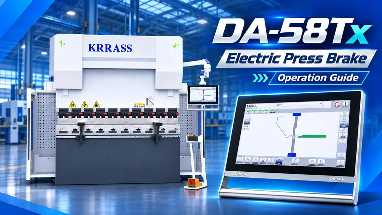
A press brake controller can display an impressive bending simulation and still produce an incorrect part if the tooling data, material information, bending sequence or machine setup is wrong. For operators who are learning the Delem DA-58Tx controller, the most useful training therefore follows the entire process: prepare the electric press brake, establish its reference positions, register the punch and die, create a bending program, perform a controlled test bend and correct the result from an actual measurement.
This guide demonstrates that workflow on a KRRASS electric press brake equipped with a Delem DA-58Tx CNC controller. It is based on the accompanying KRRASS operating video, including a practical angle-correction example in which an initial measured bend of 88.1° was adjusted to meet a 90° target on the second test. Alongside the screen-by-screen instructions, it explains the engineering reasons behind each step, calculations operators can check, common mistakes, safety considerations and a realistic method for documenting production settings.
Quick answer: To set up the DA-58Tx for a new bending job, complete the machine’s approved startup and referencing procedure; verify the punch and die profiles in the Machine tool library; choose a 2D Product or numerical Program workflow under Products; check material, backgauge and bend settings; run a safe first-part trial; measure the result; then apply verified angle corrections and save the accepted program. The controller assists with calculations, but correct tool geometry, appropriate machine guarding and physical part inspection remain essential.
Watch the complete step-by-step KRRASS tutorial:
Important scope: The video shows the workflow of a particular KRRASS machine and DA-58Tx installation. Labels, available axes, access permissions, software versions, electric drive details, tool-clamping arrangements and correction menus may differ on another machine. This article is operator education, not a substitute for the machine-specific KRRASS documentation, Delem manual, approved risk assessment or training from a qualified instructor. Only trained, authorized personnel should operate a powered press brake.
What Is the Delem DA-58Tx Controller?
The Delem DA-58Tx is a touchscreen CNC control designed for synchronized press brake applications. Delem describes it as a compact 2D graphical press brake control with an 18.5-inch multi-touch display, graphical product programming, automatic bend-sequence calculation, real-scale bend simulation and collision detection. Its interface lets the operator move between creating a product and preparing production without repeatedly reconstructing the same geometry.
The manufacturer’s official DA-58Tx product information provides the basis for the following controller-level specifications.
| DA-58Tx specification | Published manufacturer information | Why it matters in the workshop |
|---|---|---|
| Display | 18.5-inch color TFT touchscreen | Space to view bend geometry and parameters |
| Display resolution | 1366 × 768 pixels | Readability of profile and sequence screens |
| Touch technology | Projected capacitive multi-touch | Direct navigation and graphical input |
| Standard axis capacity | Up to four axes | Controller capability; installed machine axes must be confirmed separately |
| Programming | 2D graphical programming | Suitable for many profiles defined from a cross-section |
| Sequencing | Automatic bend-sequence calculation | Helps plan the order of bends |
| Simulation | Machine/tool simulation and collision checking | Assists feasibility review, subject to accurate data |
| Storage capacity | 1 GB listed | Local controller storage capability |
| Product and tools memory | 256 MB listed | Storage for program and tool data |
| Portable exchange | USB flash memory support | Relevant to data exchange and backups |
| Offline software | Profile-58TL listed by Delem | Availability, license and software compatibility must be confirmed |
| Other interfaces | Networking, Z-Link, TandemLink and OPC UA are listed as options | Do not assume an option is installed or activated |
These are controller specifications, not a guarantee that every press brake using the DA-58Tx includes every hardware capability. For example, an available crowning function does not mean a particular electric machine has a motorized crowning axis. An axis capacity of four does not establish the physical backgauge arrangement, available travel, accuracy or synchronization design.
For a wider comparison of Delem and other CNC systems, see the KRRASS press brake CNC controller guide and the CNC control system collection. These resources help buyers separate software features from the options fitted to a production machine.
Why a 2D controller can be useful in production
Much of everyday press brake production involves constant-section components: L-brackets, U-channels, Z-sections, covers and enclosure flanges. Their critical shape can often be represented by a two-dimensional cross-section, even when the complete workpiece has a substantial length or additional holes. A graphical controller lets the programmer define the profile, select tooling and consider bend order before approaching the actual machine.
That can be especially helpful when a part has several bends, a short return flange or a risk of striking the punch or machine frame. A numerical program remains valuable for simpler work, because an experienced operator can enter and modify each bend without drafting the complete profile. The DA-58Tx workflow illustrated in the video includes both approaches; neither is universally superior.
How electric drive changes the context—but not the basic bending principles
An all-electric press brake uses an electrically driven mechanism to generate and control bending motion rather than relying on a conventional hydraulic ram drive. The exact arrangement may involve servo motors, screws, belts or other mechanical transmissions; the actual machine design should be checked in its technical documentation. Electric drive does not remove the need for correct punch and die alignment, guarding, force assessment, springback compensation or periodic mechanical maintenance.
KRRASS discusses these practical trade-offs in its hydraulic versus electric press brake comparison and presents its E-Bend electric press brake family. Those pages describe product categories; they do not imply that every E-Bend configuration is supplied with a DA-58Tx. The exact CNC choice is determined by the purchased machine specification.
Understand the Screen Before You Start Programming
A good first step is to know what each relevant navigation area is supposed to accomplish. The video uses Machine, Products and Manual as the central routes through the process. Their roles are different, and confusing them often creates avoidable setup errors.
| Area or command | Primary function in this tutorial | A common misunderstanding |
|---|---|---|
| Machine | Access punch and die definitions and related machine setup | Assuming a stored tool profile proves the physical tool is installed |
| Punch library → New | Create an upper-tool definition | Entering approximate dimensions instead of the tool drawing |
| Die library → New | Create a lower-tool definition | Ignoring the actual V opening or shoulder geometry |
| Products | View or create stored jobs | Confusing the product ID with an axis setting |
| New → Product | Begin 2D graphical product creation | Believing simulation eliminates the need for trial bending |
| New → Program | Begin numerical step-by-step programming | Leaving required bend parameters at inappropriate defaults |
| Manual | Set up a single bending operation | Treating Manual mode as permission to bypass normal safeguards |
| Start / Ready | Activate the configured operating state, subject to the machine logic | Assuming a Ready indication confirms a safe or accurate setup |
| Angle correction values | Adjust a measured bending result | Changing correction signs or fields without checking their meaning |
Some software releases may place related functions in slightly different screens or use different labels. The exact source of truth for the installed machine is its current controller interface and user documentation. If an instruction does not match the delivered machine, stop and consult authorized technical support rather than guessing which command has a similar name.
Safety and Pre-Start Inspection for an Electric Press Brake
An electric press brake may be relatively quiet in standby, but its moving ram, punch, die, backgauge and workpiece still create severe pinch, crush and struck-by hazards. The sheet can rotate or rise rapidly as it bends. An incorrect backgauge position can cause interference. A loose tool segment can be dangerous even when the CNC program is otherwise correct.
The U.S. Occupational Safety and Health Administration’s powered press brake safeguarding guidance explains point-of-operation and control hazards. Its hazardous-energy control rule, 29 CFR 1910.147, addresses applicable maintenance and servicing tasks involving unexpected startup or stored energy. Follow local law, the specific machine’s safety documentation and approved site procedures; these references are not a claim that any named machine has been certified to a particular standard.
Pre-start checks worth performing every time
- Confirm authorization and work area. Keep unauthorized people away. Remove unrelated objects, scrap, loose tools and obstacles from the machine and support area.
- Examine protective systems. Confirm that relevant point-of-operation protection, side and rear guarding, emergency-stop devices and foot control protections are installed and functioning as required by the approved site inspection procedure. Never bypass a safeguard to make a program run.
- Inspect tooling and holders. Check for cracks, chips, loose segments, incorrect clamping or an unapproved mix of tools. Use the manufacturer’s specified safe tool-changing method and support heavy sections appropriately.
- Check physical clearance. Consider the ram, punch, die, backgauge fingers, sheet support, rear stops and the projected path of the workpiece during bending and removal.
- Confirm material and load limits. Identify grade, thickness, bend length and tooling capacity. Do not assume a program saved for mild steel is suitable for a stronger alloy of equal thickness.
- Verify the control state. Resolve warnings or axis faults, confirm the selected job and make sure the machine is in the intended operating mode.
- Prepare measurement and handling. Use suitable measuring instruments and safe support methods; do not hold a long or heavy workpiece in an unstable position.
Tool change safety: A touch-screen stop is not an energy-isolating device. Tool changes, jam clearing and maintenance require the protective measures specified by the machine’s approved procedures, including isolation and control of hazardous energy where applicable. Do not improvise around moving axes or enter the point of operation while an unexpected movement remains possible.
A simple start-of-shift record
| Check | Suggested record | What a failed check means |
|---|---|---|
| Guarding and emergency controls | Pass / fail / not applicable | Stop and follow the site’s safety process |
| Tool identification and condition | Tool IDs, condition, clamp status | Correct before loading the bending program |
| Material confirmation | Grade, thickness, batch | Recheck force and springback assumptions |
| Reference status | Completed / incomplete / alarm | Do not trust unreferenced axis positions |
| First-part inspection | Angle and critical dimensions | Correct process before batch release |
This short record improves traceability without pretending that a five-item checklist replaces a formal machine safety inspection.
Reference Point Search: Establishing Machine Coordinates
A reference point search, also called referencing or homing, establishes a known position for one or more controlled machine axes. Depending on the encoder system and machine architecture, startup may require specific axes to move to reference positions or complete an OEM-defined initialization sequence. Without a valid reference, a displayed numerical position may not correspond to a dependable physical location.
In the KRRASS video, the operator powers on the electric press brake, switches to Manual mode and activates the startup command. The machine begins its automatic reference point search. After the routine finishes, the machine is ready for the subsequent setup process under its normal operating conditions.
Reference point search procedure
- Complete the safety and startup checks described above. Make sure the machine is clear for the expected axis movements.
- Power on the equipment according to the specific KRRASS electric press brake operating procedure.
- Access Manual mode as shown in the tutorial.
- Activate Start or the designated reference-initiation function for that machine configuration.
- Observe the status from a safe operating position. Do not reach into the tool area to assist an axis or move stock during the routine.
- Allow the automatic referencing operation to finish. Confirm that no unresolved alarm or reference-incomplete message remains.
- Check that the machine reports a usable standby or ready-for-setup state before entering the next operation.
What referencing does not accomplish
Referencing establishes a machine-coordinate relationship; it does not confirm correct punch height, die geometry, parallelism, material thickness, backgauge finger alignment or finished-part angle. Those aspects must be checked independently. Similarly, a newly referenced machine should not immediately be assumed to be calibrated after a collision, sensor replacement or mechanical service.
If referencing fails, do not repeatedly command movement hoping the error will disappear. Record the displayed fault, inspect the machine’s documented status and ask an authorized technician to diagnose sensor, limit, drive, communication or mechanical issues. Repair work should be carried out under the approved isolation procedure.
How to Add a Punch to the DA-58Tx Tool Library
A punch is the upper bending tool. During an ordinary air-bending operation, the punch applies force to the sheet at the bend line while the lower V die supports it. The punch’s nose radius, tip angle, height and full body profile affect achievable geometry and clearance. For example, a deep box with return flanges may need a gooseneck punch rather than a straight punch because the already-formed portion can collide with the tool on a later step.
A CNC control does not automatically know which tool is physically mounted. The punch library stores the geometric description and identifying information used for programming and simulation. Registering a tool in software is only one part of setting up that tool on the machine.
Adding a new punch, step by step
- Tap Machine to enter the area used in the video for machine information and tooling definitions.
- Find the Punch library or punch list.
- Select New beside the list to create a fresh definition rather than changing a production tool unintentionally.
- Enter a meaningful Punch ID or name. The name should match the physical tool marking and your workshop tool register.
- Enter the tool properties requested by the controller, following the actual punch drawing. The exact sequence and available shape choices depend on the software version.
- Open the punch profile editor and define the cross-section segment by segment. Carefully enter the lengths and angles of the visible outline.
- Review the shape, tip geometry, orientation and dimensions before accepting the new definition.
- Save the tool according to the on-screen workflow. Confirm it can be found again by its ID and that its graphical profile matches the installed punch.
If the control offers a selection of standard tool shapes or a guided geometry editor, select the one appropriate to the tool. Do not force a complicated gooseneck profile into a generic straight-punch model if its clearances will be used for collision analysis.
Punch data that deserve special attention
| Punch attribute | Role | Practical verification |
|---|---|---|
| Tool ID | Connects the library to a physical tool | Compare with engraving, packing list or shop register |
| Overall height | Affects machine geometry and Y-position calculations | Confirm the drawing’s reference points and units |
| Tip angle | Influences forming clearance and feasible angle range | Compare with the specified tool angle |
| Nose radius | Influences local forming behavior and material cracking risk | Verify nominal and actual tool condition |
| Body profile | Used for clearance and collision checks | Trace return-flange and gooseneck areas accurately |
| Orientation | Determines which side of an asymmetric tool faces the part | Confirm physical installation direction |
| Segment length | Defines usable tooling length along the machine | Verify the actual segments fitted |
| Load rating | Limits permitted force per tool or length | Consult the tool manufacturer’s rating, not the drawing alone |
Example, not a supplied KRRASS tool specification: A workshop might register a tool under P-STD-88-R1 if its internal naming convention identifies a standard-style punch with an 88° tip and 1 mm nominal radius. That ID is only an illustrative naming example; never infer dimensions from a name without verifying the tool drawing and actual tool.
Why inaccurate punch geometry creates real problems
If a modeled punch is too short or too slim, simulation may display a gap where the actual tool would strike a flange. If its reference height is wrong, the controller’s calculated ram position may not match the actual tooling setup. If the nose radius is entered inaccurately, theoretical bend geometry may not match the formed part. Tool wear and regrinding can further separate the original drawing from the physical tool.
For these reasons, the 2D profile should be treated as engineering data, not artwork. Keep the original manufacturer drawing, verify critical dimensions after tool changes and use the supplied tooling guidance when editing a geometry that affects collision clearance or machine travel. The KRRASS press brake tooling guide covers standard, acute, radius and gooseneck punch selection in more detail.
How to Add a Die and Define the V Opening Correctly
The die is the lower tool. In common air bending, a V-shaped groove provides two principal support regions while the punch moves the sheet into the opening. The die geometry helps determine required force, the naturally formed inside bend radius, achievable flange length, contact marking and part stability.
The KRRASS video registers the lower tool using the Die library, then defines its outline from the technical drawing. This process mirrors punch registration but requires particular care with the V opening: the width should correspond to the actual applicable die opening, not an assumed value taken from the material thickness alone.
Adding a new die, step by step
- Return to Machine and open the Die list.
- Tap New to start a new lower-tool definition.
- Enter the required Die ID, name and initial properties.
- Open the die profile editor.
- Follow the actual die technical drawing and enter the relevant segment lengths, angles and other requested dimensions.
- Check that the geometry shows the correct single V groove when the installed tool is a conventional single-V die. A multi-V die should only be modeled if the physical tool actually has that configuration.
- Verify groove width, included angle, overall height, shoulder geometry and orientation as applicable.
- Save the definition and inspect the displayed profile before selecting it in a bending program.
Basic V-die geometry: a drawing must match the physical tool
Some confusion arises when tool drawings mix overall die width, the distance between outer shoulders and the actual nominal V opening. These are not interchangeable. The V opening is the relevant opening dimension specified for the die, usually measured across the working geometry defined by the tooling manufacturer. The software may ask for additional distances, but their exact references must be taken from the controller prompts and the tool drawing.
Do not enter two separate narrow V grooves in a control profile to imitate one continuous groove. Do not represent a standard V die as a trapezoidal channel. A wrong profile can make an unrealistic bending simulation look plausible, undermining the very purpose of graphical programming.
Starting V-opening values for ordinary air bending
A widely used planning guideline for conventional air bending of many mild-steel sheets is a V opening around 6–8 times the material thickness. This is only a starting range; final choice depends on material, radius, short-flange requirements, surface finish, tool capacity and the bend method. The values below are calculated from that rule, not presented as mandatory Delem settings or universal manufacturing limits.
| Sheet thickness | V opening at 6 × thickness | V opening at 8 × thickness | Engineering consideration |
|---|---|---|---|
| 1.0 mm | 6 mm | 8 mm | Confirm material handling and small-tool capacity |
| 1.5 mm | 9 mm | 12 mm | Check short flanges and cosmetic surface requirements |
| 2.0 mm | 12 mm | 16 mm | Common planning range for light-gauge fabricated parts |
| 3.0 mm | 18 mm | 24 mm | Compare radius, load and minimum flange |
| 4.0 mm | 24 mm | 32 mm | Check force and maximum tool load per meter |
| 6.0 mm | 36 mm | 48 mm | Verify machine capacity and bending method |
The KRRASS tooling selection article discusses these trade-offs and explains why a wider die is not always a better die. It usually lowers air-bending force but tends to increase the formed inside radius and require a longer supporting flange. For a small enclosure, the short flange—not available tonnage—may become the limiting factor.
The minimum flange problem
During an air-bending cycle, the flange must remain properly supported by the die shoulders as the workpiece moves. If the flange is too short for the chosen opening and actual geometry, the sheet may lose stable support, slip or form unpredictably. A commonly used early estimating ratio is about 0.7 × V for a minimum flange, but this is not a process approval. Actual minimum length must come from the toolmaker’s data, the required bend angle, sheet thickness and tested process.
For example, the rough 0.7 × V estimate is 11.2 mm for V16, 16.8 mm for V24 and 22.4 mm for V32. These values are useful when screening a drawing, not when authorizing an unfamiliar high-load bend. If a designed flange is too short, investigate approved narrower tooling, a changed bend sequence or a drawing revision before moving ahead.
How to Create a 2D Graphical Bending Product
For many multi-bend profiles, 2D graphical programming is one of the DA-58Tx’s most useful capabilities. Instead of defining only isolated movements, the operator describes the desired cross-section of the finished workpiece. The controller then uses the defined geometry, material settings, selected tools and machine configuration to help calculate the bending process.
Delem identifies automatic bend-sequence calculation and collision detection as DA-58Tx functions in its manufacturer specification. These calculations depend on the accuracy of the data and the installed machine’s modeling capability; they do not remove the need for a safe production review.
Step-by-step 2D product creation
- Tap Products to open the stored product and program list.
- Select New, then select Product, following the workflow demonstrated in the video.
- Enter a unique Product ID and the product-related values requested by the software. Use a consistent naming system linked to the drawing revision.
- Enter the 2D editor. Build the profile by specifying each relevant straight segment and the required bend geometry in the correct order.
- Review material information and part dimensions. Confirm that you understand whether each screen expects an included angle, bend angle, inside radius or another geometric convention.
- Choose the correct punch and die from their libraries. Make sure their actual orientation and installed positions match the software model.
- Use the controller’s sequencing function to calculate a possible set of bending steps and bend order.
- Inspect the result graphically, looking for flange interference, part handling problems, inadequate backgauge support and tool collisions.
- Where permitted by the software, adjust the bending sequence or step details to suit the real production setup.
- Save the job, complete the machine’s pre-production checks and prepare a controlled first-part test.
Why bending sequence matters
A simple U-channel may appear straightforward on paper but can still present tool-clearance issues depending on flange height and punch profile. A deep enclosure with inward return flanges is more demanding: after early bends, the sheet may no longer fit between a straight punch and the machine or may collide with its own formed edges. Reversing the order can sometimes solve the problem; in other cases, special tooling or a design change is needed.
A good sequence balances physical feasibility, part handling, measurement access and repeatability. The calculated sequence is a starting proposal. Before running the program, assess the actual motion and the operator’s ability to position and support the part throughout all bends.
Example: comparing alternative bend sequences
Consider a hypothetical profile with four bends for an electrical enclosure. The proposed sequence may form the two outer flanges first, then the inner bends. This can be efficient for one tool shape but awkward for another. The alternatives should be evaluated against concrete criteria rather than operator preference alone.
| Review criterion | Questions to ask before approving a sequence |
|---|---|
| Tool clearance | Will any already-formed flange strike the upper tool or holders? |
| Backgauge access | Can the workpiece contact the gauge reliably before each bend? |
| Part handling | Does the sheet become difficult or hazardous to support? |
| Dimension control | Which bend order best preserves the critical reference dimension? |
| Surface quality | Will an intermediate operation scratch a finished surface? |
| Tool changes | Can the program avoid unnecessary, unsafe changeovers? |
| Inspection | Can the critical angles and flange lengths be measured appropriately? |
Simulation limitation: A clear simulated view is useful but is not proof that physical clamps, tooling, stock thickness, protective systems, add-on equipment or real workpiece deformation will match the virtual model. Unknown geometry should be checked using a conservative, authorized setup and appropriate trial procedures.
Save part identity, not just the bending motion
A useful job identifier contains the drawing or customer part number, revision and, where practical, material or process variant. Consider a convention such as ENC-042-R03-SS for an illustrative enclosure drawing revision. This avoids mistakenly recalling an old program after a drawing change. The controller’s available identifier fields and maximum character lengths should be checked before establishing the naming convention.
Store the production drawing and setup sheet outside the machine as well, using the factory’s document-control system. A machine program is not a replacement for the approved drawing, inspection criteria or required traceability records.
How to Create a Numerical Bending Program
The second programming method shown in the video starts with Products → New → Program. Instead of requiring the full 2D product shape, this workflow lets the operator create a numerical bending program by defining its individual bending steps and related values.
This method can be efficient when a part is simple, the required sequence is already known or an operator must make a controlled adjustment to a repeated operation. It also places more responsibility on the programmer to check dimensions, the intended bend method and every step’s parameter settings. Do not assume that a numerical entry will be independently validated against a complete part profile.
Step-by-step numerical programming
- Open Products and select New.
- Choose Program rather than Product.
- Enter a unique Product ID and other required job information.
- Open the program editor associated with the new numerical job.
- Select the correct punch and die as shown in the tutorial.
- Add the first bending step and enter the applicable parameters requested by the controller—for example target angle, bend length, material and axis/backgauge settings, depending on the installed configuration.
- Add the remaining bends one at a time. Confirm that each step represents an achievable, safe part-handling and gauging operation.
- Review all steps for incorrect values, units, tool selection, omitted operations and unwanted copied defaults.
- Save the program and perform the required first-part verification before routine production.
Numerical parameter groups to understand
| Parameter group | What it influences | What must be checked |
|---|---|---|
| Target angle or forming position | Intended final bend geometry | Drawing convention and springback behavior |
| Bending length | Force calculation and tool load | Actual contact length on the installed die |
| Material and thickness | Force, depth and correction assumptions | Verified material grade and measured thickness |
| Punch and die IDs | Geometric calculations and machine clearance | Physical tool identity and orientation |
| Backgauge position | Flange dimension and bend-line location | Gauge finger contact and measurement datum |
| Axis correction | Fine adjustment of a measured result | Correct field and sign in current software |
| Bending speed | Motion profile during the forming stage | Limits and process suitability for the job |
| Sequence and step number | Order in which the part is formed | Operator handling and collision feasibility |
Not all parameters appear on every software page, and the hardware may not support every possible axis. Apply only values that the installed controller and machine are designed to accept.
2D Product versus numerical Program: which should you use?
| Question | 2D Product workflow | Numerical Program workflow |
|---|---|---|
| Is a full part cross-section required? | Normally central to the method | Not necessarily |
| Does the workflow assist bend-sequence planning? | Yes, graphical sequencing is a key feature | Operator usually defines individual steps more directly |
| Is it helpful for complicated return flanges? | Often, especially with correct tool geometry | Possible, but requires more manual clearance planning |
| Is it suitable for a simple repeated bend? | Yes | Often particularly convenient |
| Can you change angles and tool settings? | Yes, within available workflow | Yes, via programmed step parameters |
| Does either method eliminate first-part inspection? | No | No |
Recommended decision rule: Choose the method that allows the particular part to be defined, reviewed and reproduced with the least ambiguity. For a complicated profile, start by exploring the 2D Product route. For a straightforward repeated operation, a numerical Program may be more direct. Test both methods on representative factory parts rather than assuming one method will always be faster.
Setting Up Manual Bending on the DA-58Tx
Video demonstration: 05:07 — Setting Up Manual Bending
Manual mode is useful for controlled single-step bending, initial setup, test pieces and some low-volume work. It is not the same as a manually operated mechanical press brake. The DA-58Tx still works with the installed machine’s programmed movement, control functions and safeguarding; it simply allows the operator to work with a single bending setup rather than a longer multi-step product sequence.
In the video, the operator taps Manual, enters the desired bending parameters, then uses the start control in the upper-right region of the interface to enter the Ready state. The actual bending cycle can then proceed under the machine’s normal authorized operating method.
Manual bending setup sequence
- Confirm the machine has been referenced and all startup checks have passed.
- Verify that the selected upper and lower tools are physically installed, properly clamped and correctly represented in the tool library.
- Tap Manual to open the single-step bending screen.
- Enter or review the material, thickness, required bend angle, bending length and other applicable setup values.
- Verify any displayed speed, axis and backgauge parameters against the job requirements and machine instructions.
- Confirm that the sheet is correctly supported and can be positioned against the intended reference without an unsafe posture.
- Activate Start as demonstrated to prepare the selected setup. Observe the Ready indication and any faults or interlocks.
- Follow the approved machine operating procedure for the test bend. Do not assume the Ready display itself initiates or guarantees a safe bending stroke.
- Remove the part safely, measure it using an appropriate tool and record the result before changing a correction value.
Manual-mode settings that matter most
The correct target angle is essential, but it is only one variable. The same displayed angle may produce different physical results if the material thickness changes, the V die is replaced or the workpiece is supported differently. Backgauge positioning affects flange dimensions, while die opening and bending force influence the part’s radius and springback.
For operators learning the interface, one effective approach is to make a short setup sheet containing the actual material, tool identities, target dimensions and tested settings. This avoids using memory to reconstruct a successful first article later in the shift. It also helps identify which variable changed when a previously acceptable part begins to drift.
Bend Angle Correction: From 88.1° to 90° in the Video
A controller program represents the desired result. A measured workpiece shows what the specific material, tooling, machine and process actually produced. The difference is why experienced press brake operators rely on a first-part measurement rather than treating calculated bending depth as a finished-part guarantee.
The final section of the KRRASS video provides a concrete example. The operator performs a test bend using the Manual mode settings and measures an angle of approximately 88.1°. The intended angle is 90°, so the measured included angle is 1.9° smaller than the target. The operator returns to the Manual page, enters 1.9° into each of the two demonstrated angle-correction fields, reduces the selected bending speed from 25 mm/s to 8 mm/s, and performs a second test bend. The subsequent measurement reads 90°.
Recorded tutorial data
| Item | First trial | Corrected trial | Source and interpretation |
|---|---|---|---|
| Programmed target included angle | 90° | 90° | Target used in the KRRASS demonstration |
| Measured finished included angle | Approximately 88.1° | 90.0° | As measured on camera |
| Signed measurement error (actual − target) | −1.9° | 0.0° | Arithmetic from the reported angles |
| Magnitude of angle error | 1.9° | 0.0° | Absolute difference from target |
| Two demonstrated correction entries | Prior settings not specified | 1.9° entered in each field | Video input, not a universal controller instruction |
| Selected bending-speed setting | 25 mm/s | 8 mm/s | Both settings shown in the tutorial |
| Result | Requires correction | Meets displayed 90° target | One demonstrated test, not a statistical capability study |
The basic measurement calculation is straightforward:
Angle error = measured angle − target angle
Initial error = 88.1° − 90.0° = −1.9°
Absolute error = |−1.9°| = 1.9°
The corrected measurement is 90.0° on the measuring device used in the video. That does not establish that every part produced with these settings will have zero error, or that the true angle is known to infinite precision. A single displayed reading is subject to instrument resolution, calibration, positioning, operator technique and part variation.
A critical distinction: recorded input versus universal correction sign
The video demonstrates values entered into a particular controller setup. It should not be interpreted as an instruction to always apply a positive 1.9° correction whenever a measured included angle is smaller than 90°. Different controller parameters can use different sign conventions, and a correction may represent angle, ram-depth compensation or a side-specific adjustment. Before entering a value on another machine, check the software label, the current machine manual and the direction of the previous measured error.
Similarly, the two 1.9° entries must not automatically be described as independent proof of a Y1/Y2 geometric correction unless the screen labels and machine setup confirm their purpose. If they are side-specific values on your version, they should be entered and verified according to their defined function. Do not change both sides mechanically or electronically merely because a video shows two editable fields.
Can the improvement be credited to angle correction alone?
Not conclusively. The demonstration changes two things between the measured bends: correction values and the displayed speed setting. The second part meets the target, but the video does not isolate the contribution of the correction entries from the speed change, material behavior or other variation. It is accurate to report the combined sequence and resulting measurement; it would be misleading to claim that lowering the speed alone caused a particular angular improvement.
For production engineering, change one relevant variable at a time where practical, document it and confirm the result with repeated parts. If process constraints require simultaneous changes, record them as a combined setup change rather than attributing the outcome to one factor without evidence.
A repeatable correction workflow for operators
- Confirm the programmed target. Identify whether the drawing and controller are displaying the same definition of angle. An included angle and a bend-through angle are not automatically identical values.
- Measure the test piece. Use an appropriate angle instrument with an agreed contact method. Avoid measuring on a burr, radius transition or damaged surface.
- Record the signed deviation. Write down actual minus target, along with the tool, material batch, thickness and measurement location.
- Identify the correct field. Consult the DA-58Tx screen labels and OEM documentation to distinguish general angle compensation, side-specific correction and motion parameters.
- Enter a controlled correction. Use the machine-specific sign convention and permissible range. Do not make large unverified changes or exceed machine limits.
- Perform a new authorized test. Keep as many other conditions constant as practical. Verify that any intended speed change is also recorded.
- Measure again. Compare against the drawing tolerance and evaluate whether additional refinement is actually needed.
- Verify repeatability. Check more than one accepted part and, for longer bends, measure more than one point along the bend.
- Save and identify the approved setup. Link the successful settings to the relevant drawing revision and material condition.
Why the measured angle may be wrong before correction
Springback is a major reason. As the forming load is removed, elastic strain recovers and the metal typically moves away from the shape it had under the punch. The amount depends on material strength and temper, thickness, radius, V opening and the type of forming process. Even sheets labeled with the same nominal grade can vary enough to require a fresh first-part check after a batch change.
Other causes include an inaccurate tool profile, a wrong V opening, incorrect material thickness, tool wear, machine deflection, backgauge contact problems, variable sheet support or a measurement convention mismatch. A compensation value is useful only after identifying the dominant cause. Otherwise, the operator may be hiding an incorrect setup behind an increasingly large adjustment.
Angle consistency across a long bend
Suppose a long part measures 89.5° at the left end, 90.0° in the center and 90.6° at the right end. These illustrative readings, not data from the KRRASS video, show that a single overall correction may not solve a side-to-side or lengthwise variation. Possible factors include tool seating, ram/bed alignment, asymmetric loading, uneven material, support behavior and the actual crowning arrangement.
The right response is not to assume every discrepancy can be solved by entering different angle offsets. Check the physical setup, follow OEM diagnostics and verify whether the delivered machine actually has the relevant axis or crowning hardware. For persistent differences, ask qualified service or engineering personnel to inspect the machine within its approved adjustment limits.
Understand Bending Force Before Accepting a Program
A 2D program can calculate a sequence, but the finished job must still fit within the machine’s rated force, permitted load distribution, tooling capacity and operating envelope. Material thickness is especially important because the bending force rises rapidly as thickness increases.
KRRASS publishes an online press brake tonnage calculator and explains the principle further in its tonnage calculation guide. One simplified metric planning relationship presented by KRRASS is:
F ≈ (65 × S² × L / V) × C
For this illustrative calculator convention:
F= estimated bending force in metric ton-force (tonnes-force), rather than a mass value;S= sheet thickness in millimeters;L= bend length in meters;V= nominal V-die opening in millimeters;C= material correction factor, with 1.0 as the selected mild-steel reference.
This is an empirical starting estimate for an appropriate air-bending case, not a universal physical law. The coefficient and chosen correction factor depend on the calibration assumptions. Other published equations use different coefficients, units or material strengths; do not mix them. Convert to force units if needed using approximately 1 metric ton-force = 9.80665 kN.
Illustrative bending-force estimates
The following calculations deliberately set C = 1.0 and use the same simplified formula. They do not represent guaranteed machine capacity or recommended production settings.
| Thickness S | Bend length L | V opening | Calculated force, approx. | Typical review needed |
|---|---|---|---|---|
| 1.0 mm | 1.0 m | 8 mm | 8.13 tf | Confirm small-tool rating and material support |
| 1.5 mm | 0.6 m | 12 mm | 7.31 tf | Check tool setup and actual thickness |
| 2.0 mm | 0.5 m | 16 mm | 8.13 tf | Check half-meter tool load and machine limits |
| 2.0 mm | 1.0 m | 16 mm | 16.25 tf | Baseline comparison for a 2 mm sheet |
| 2.0 mm | 1.0 m | 12 mm | 21.67 tf | Smaller opening raises estimated force |
| 2.0 mm | 1.0 m | 20 mm | 13.00 tf | Wider opening lowers force but affects geometry |
| 3.0 mm | 1.0 m | 24 mm | 24.38 tf | Confirm longer-flange and tooling load requirements |
| 4.0 mm | 1.0 m | 32 mm | 32.50 tf | Check rated capacity and local tool loading |
These figures illustrate three major relationships. At fixed material, length and V opening, estimated force grows with thickness squared. Doubling thickness from 2 mm to 4 mm, without changing the other inputs, increases the mathematical estimate by a factor of four. At fixed thickness and V opening, doubling bend length doubles force. At fixed thickness and length, widening the V opening decreases the simple force estimate, although it also changes radius and flange feasibility.
Real jobs can differ from these estimates because tensile strength, material condition, bending method, friction and tool shape vary. High-strength alloys, stainless steel and special forming operations should not be authorized with C = 1.0 simply because a calculator allows that entry. When determining an actual machine/tool package, use the manufacturer’s qualified force tables and allowed off-center loading requirements.
A numerical example connected to the control setup
For an illustrative 2.0 mm mild-steel strip, a 1.0 m bend and a V16 lower die, the basic estimate is 65 × 2² × 1.0 / 16 = 16.25 tf, equivalent to roughly 159 kN. That value is a preliminary total forming-force estimate; it is not necessarily the peak force that would be recorded on a particular machine.
Before using the DA-58Tx to produce this part, the operator should confirm that the actual V opening is 16 mm, the material grade matches the assumption, the programmed bending length represents the real contact length and the machine and both tools can safely withstand the loading. A correct on-screen tool drawing cannot compensate for an undersized or damaged physical tool.
Material, Bend Radius and Flat-Pattern Accuracy
A correct final angle does not guarantee a correct finished component. A part can measure 90° and still have the wrong flange length, outside dimensions, inside radius or hole location. This becomes important when the DA-58Tx is used to create a full 2D Product instead of a single test bend.
The bend allowance estimates the length of material associated with the bent portion of a flat pattern. A common engineering approximation is:
BA = θ × (π / 180) × (R + K × t)
where θ is the bend angle used by the bend-allowance convention, R is the inside radius, t is material thickness and K is the neutral-axis factor. This is a development equation requiring a consistent geometric convention; it does not mean the angle shown on every controller screen is automatically the correct θ input.
For instance, a hypothetical 90° bend with R = 2.0 mm, t = 2.0 mm and K = 0.40 gives approximately BA = (π/2) × (2.0 + 0.40 × 2.0) = 4.40 mm. This value is an illustrative model, not a measured K-factor for a particular steel or a DA-58Tx default. Actual production should use validated bend tables or experimentally determined allowances for the selected material, tools and process.
See the KRRASS bend allowance and bend deduction guide for further discussion of flat-pattern calculations and K-factor assumptions.
Why reference surfaces matter for flange length
When the operator positions a sheet against the backgauge, the meaning of the programmed dimension depends on the datum and how the material is presented. A burr, curved blank, slanted edge or previously formed flange can prevent consistent contact. Measuring a flange from the wrong tangent point after bending can create the appearance of a controller error when the problem is actually the inspection method.
For each important product, document whether the drawing dimensions are inside, outside or tangent-related; how the blank is referenced against the gauge; and how the inspector will measure the finished part. When tolerance is tight, validate the actual bend deduction and reference procedure instead of relying entirely on a generic material table.
Troubleshooting Common DA-58Tx Setup and Bending Problems
Before troubleshooting a software problem, determine whether it is a programming issue, a measurement issue, a physical tooling problem or a machine fault. Changing random parameters may temporarily alter the result but make the root cause harder to diagnose. The table below provides conservative first checks for trained personnel. It is not permission to open guarded cabinets, defeat interlocks or service drives without authorization.
| Symptom | Possible cause to investigate | Appropriate first action |
|---|---|---|
| Machine does not complete referencing | An unresolved alarm, interlock, reference or drive issue | Record fault text and follow the machine’s diagnostic procedure |
| Punch cannot be found in a program | Tool ID mismatch or tool was not saved | Check saved library entry and naming convention |
| Die profile looks wrong | Incorrect dimensions, angle convention or shape selection | Compare the profile with the actual toolmaker drawing |
| Calculated tool position appears implausible | Wrong tool height, unit, material or selected operation | Review inputs; do not proceed to an unverified trial |
| 2D bend sequence creates interference | Inaccurate geometry or an unsuitable bend order | Recheck simulation and evaluate alternative approved tooling/sequence |
| Product bends in the wrong order | Step sequence is incorrect for physical handling | Review steps before production and correct the job file |
| First bend is too open or too closed | Springback, tool data, material variation or wrong correction | Verify measurement, inputs and correction sign |
| Angle is inconsistent across a long bend | Deflection, tooling alignment, load distribution or material variation | Document locations; involve qualified engineering or service personnel |
| Flange length varies between parts | Inconsistent gauge contact or blank geometry | Inspect workpiece reference, burrs and gauge setup |
| Tooling leaves unwanted marks | Die shoulder contact, material surface or protective-method mismatch | Review tooling and approved surface-protection options |
| Production program was overwritten | Weak naming or revision control | Restore from an approved backup and validate before running |
| 90° reading cannot be reproduced | Material, tool, measuring method or process has changed | Compare setup records and repeat a controlled sample study |
If the program shows an angle error, do not immediately change the Y-axis setting
The visible error may result from the material’s springback rather than a mechanical Y-axis defect. Start by confirming the drawing target, measuring method, material grade, thickness, die opening and existing correction values. If those are consistent and the machine behaves abnormally, stop using trial adjustments as a substitute for authorized diagnostics. Persistent position or synchronization errors require inspection under the OEM’s procedures.
If tooling data looks correct but simulation misses a collision
Ask whether the actual tool holders, segmented tooling, nonstandard mounting, previously formed flange and backgauge fingers are accurately represented. A basic 2D display may not model every real-world obstruction. A safety-related collision concern must be resolved before production—not worked around by running the machine slowly and hoping the part will clear.
If different operators get different results
Standardize the process before blaming the controller. Use the same material batch, verified blanks, tool set, backgauge datum, inspection gauge and written setup. Record any permitted corrections and the selected program revision. When those conditions are controlled, repeated differences become easier to investigate and training needs become visible.
Production Quality Control: From Successful Test Bend to Repeatable Work
One accepted test piece is useful, but repeatability asks a different question: will the next pieces stay within the same required tolerance? The answer depends on variation across material, tooling, handling, measurements and machine condition. It should be demonstrated with representative samples rather than guessed from the CNC screen resolution.
For a job with a specified target and tolerance, establish what actually matters on the drawing: bend angle, flange dimension, hole position after bending, inside radius, cosmetic surface, or fit against a mating part. A finished product should be judged against those requirements, not simply whether the controller reports completion.
Suggested first-article and production verification sheet
| Record field | Example entry format | Purpose |
|---|---|---|
| Part / revision | ENC-042 / Rev C | Prevents use of an obsolete program |
| Material | Grade, temper and batch | Links springback behavior to incoming material |
| Measured thickness | Actual readings in mm | Detects variation in material thickness |
| Punch / die | Saved IDs and actual installed tools | Connects physical and digital setup |
| V opening | Actual selected opening in mm | Controls force and radius assumptions |
| Program ID | Saved controller product/program ID | Supports repeat production |
| Target / tolerance | Drawing requirement | Defines acceptance |
| First-part result | Angle and flange measurements | Captures initial process outcome |
| Final correction | Parameter name and saved value | Allows the approved setting to be recovered |
| Inspection method | Instrument and measurement location | Makes readings comparable |
| Release decision | Authorized accept/reject record | Separates trial production from released work |
The identifiers in this table are examples only. The factory should adapt them to its actual quality system, document controls and inspection requirements.
Example of a simple repeatability check
Imagine an illustrative, not video-derived, sequence of five readings: 89.9°, 90.0°, 90.1°, 90.0° and 90.0°. Their average is 90.0°, while the observed range is 0.2°. That is more informative than reporting only one of the readings. Yet it still does not by itself establish a process capability index, because a meaningful capability study needs an appropriate measurement system, stable process, agreed tolerance and sufficient representative data.
Record the measurement device’s resolution, condition and applicable calibration requirements. A digital protractor that displays tenths or hundredths of a degree does not necessarily guarantee the same absolute accuracy. The contact surfaces, bending radius and operator technique can affect the reading as much as the display’s number of decimal places.
Speed and productivity should be measured, not assumed
An electric press brake may offer good motion responsiveness for suitable work, but total part throughput includes more than ram travel: blank retrieval, positioning, foot-control activation, support, part rotation, inspection and stacking all consume time. Changing a displayed bending speed from 25 to 8 mm/s, as in the video, is a process-setting change, not a measured statement about total parts per hour.
A simple productivity calculation illustrates the distinction. If a hypothetical workshop reduces its average setup time from 20 minutes to 12 minutes for six job changeovers per day, the potential time released is (20 − 12) × 6 = 48 minutes per day. That is an assumption-based model, not a documented saving from the featured KRRASS video. The workshop must measure actual setup times, reject rates and staffing before attributing any savings to the DA-58Tx or an electric drive system.
For procurement decisions, compare complete processes using the same parts and acceptance criteria. KRRASS’s press brake machine buying guide discusses how tonnage, bending length, control functions, tooling and service must be evaluated as a system rather than as isolated features.
DA-58Tx Operator Questions: Frequently Asked Questions
1. Is the Delem DA-58Tx suitable for an electric press brake?
The DA-58Tx can be used as part of a properly engineered and integrated press brake control system, and the KRRASS video demonstrates its operation on an electric press brake. Suitability depends on the complete OEM implementation, including the servo-drive architecture, feedback, machine control, guarding and software configuration. Confirm the delivered machine specification instead of assuming any control can be fitted to any electric machine without engineering work.
2. Does the DA-58Tx support 2D graphical programming?
Yes. Delem lists 2D graphical touchscreen programming, bend-sequence calculation and simulation among its features. The tutorial demonstrates Products → New → Product for a graphical workflow. Correct results still depend on accurately entered part and tool data and a physically achievable bending process.
3. What is the difference between New Product and New Program?
In the demonstrated workflow, New Product begins a 2D graphical product definition, while New Program starts a numerical bending program with individual steps. A Product workflow is useful when working from a cross-section and evaluating sequence; a Program workflow is direct when the steps are already known. Use the menus and documentation available on your installed software version.
4. How do I add a new punch or die?
From Machine, open the appropriate Punch or Die library, choose New, enter the identification information and define the profile from the actual tooling drawing. Review every dimension and angle before saving. Library registration does not install or clamp the tool; verify the physical tool separately using the approved safety procedure.
5. Why must I enter punch and die geometry accurately?
The geometry influences calculations and clearance checking. A wrong tool height or profile may lead to incorrect positions or a misleading simulation. An incorrect V opening can also change the estimated force, inside radius and minimum flange feasibility. Always use verified tool drawings rather than approximate outlines drawn from memory.
6. Does the DA-58Tx automatically prevent every collision?
No. The manufacturer describes collision detection and simulation capabilities, but the effectiveness of a check depends on the model and data represented in the software. Unmodeled holders, sheet behavior, workpiece handling, incorrect dimensions and physical machine details may still create hazards. Simulation is a planning aid, not a replacement for guarding or a machine-specific safety review.
7. What does Reference Point Search do?
It establishes an expected machine reference for the controlled axes under the OEM startup procedure. It does not calibrate the bending process, prove the tooling is correctly installed or confirm that a part will bend to the target angle. If referencing produces an alarm, diagnose it before proceeding.
8. Can I bend a part in Manual mode?
Yes, when the installed machine supports the demonstrated Manual operation and all required settings and safety conditions are satisfied. Manual mode is especially useful for a single test bend or straightforward operation. It does not mean that physical safety controls can be bypassed or that the operator should guide a moving workpiece into a hazardous location.
9. Why did the first video test produce 88.1° instead of 90°?
The video documents the measurement, but does not establish one unique cause. Common reasons for a first-part angle difference include material springback, tool and die details, thickness, process settings and correction state. The operator should check these variables before deciding which programmed adjustment is appropriate.
10. What angle correction was entered in the tutorial?
The operator entered 1.9° into two demonstrated angle-correction fields and changed the selected bending speed from 25 mm/s to 8 mm/s. The subsequent test measured 90°. The correct field identities, signs and permissible values must be confirmed on the specific controller; do not reuse those inputs blindly for another part or machine.
11. Does a 90° second test guarantee every future bend will be 90°?
No. It shows that the demonstrated second part met the displayed target measurement. Repeated production should be checked against the actual drawing tolerance with a suitable instrument and sample plan. Material batches, tool condition, handling and machine drift can change results even when a stored program remains unchanged.
12. Is a wider V die always better for an electric press brake?
No. A wider opening generally reduces preliminary air-bending force but tends to increase the inside radius and requires more flange support. A narrower opening may help achieve short flanges but increase the force and marking risk. The right choice depends on the drawing, material, machine load limits and actual tooling rating—not on the drive type alone.
13. Can the controller’s displayed speed be compared with machine productivity?
Not directly. The screen may show a programmed speed for a phase of motion, while complete throughput depends on the whole cycle and all handling tasks. A single speed setting is not equivalent to parts per hour, energy use or first-pass yield. For a fair comparison, measure completed, accepted parts under representative conditions.
14. Can I transfer programs using USB or network connections?
Delem lists USB exchange capability for the DA-58Tx and publishes several connectivity options. Network functions, software licenses and interfaces depend on the particular installed controller configuration. Use approved backup/export procedures and verify transferred programs and tooling references before production. Do not assume that a transferred file automatically recreates the physical machine setup.
15. Does the DA-58Tx include offline programming software?
Delem lists Profile-58TL as the associated offline software. Availability, licensing, installation requirements and authorization arrangements must be checked with Delem or the authorized equipment supplier for the specific software package and delivery. The controller’s online product listing is not proof that an offline software license is included with every machine purchase.
16. What should I provide when asking KRRASS for a machine or controller recommendation?
Provide part drawings, material grades, minimum and maximum thicknesses, longest bend length, required bending accuracy, expected yearly quantities, short-flange and return-flange details, plant electrical supply, available floor space and relevant safety requirements. If you already have a press brake, include its model, controller revision, installed axes and a description of the operation you want to improve. This allows the recommended configuration to be matched to production needs rather than to a generic controller feature list.
Practical Takeaways for Better DA-58Tx Bending Results
The Delem DA-58Tx controller helps organize press brake work through stored tooling information, graphical product programming, numerical steps and adjustments based on actual parts. Its value is greatest when the software data and shop-floor conditions agree: the punch and die on screen must match the installed tools, the material inputs must match the sheet, and the production sequence must match the real workpiece and machine clearances.
The KRRASS tutorial connects these principles in one continuous operating example. It starts with referencing, moves through punch and die registration, demonstrates 2D Product and numerical Program workflows, then uses Manual mode and a measured test bend to verify the outcome. The final measured correction from 88.1° to 90° is a useful demonstration of a disciplined feedback process—not a promise that all jobs can be corrected by the same numeric input.
For the best results, keep safety checks independent of programming checks, treat simulated sequences as plans rather than safety guarantees, verify bending force before choosing tooling, document first-article measurements and record the exact settings associated with an accepted part. These habits are just as important as learning where to tap on the touchscreen.
Watch the full KRRASS DA-58Tx electric press brake tutorial on YouTube to follow the controller screens from startup to angle correction. To explore a machine matched to your workpieces, review the KRRASS press brake range, electric E-Bend family and available CNC control systems, or contact KRRASS with your drawings, materials and target production requirements.
Technical editorial note: The operational sequence and angle-correction numbers are taken from the KRRASS video linked above. Manufacturer-level controller specifications are attributed to Delem. Force and tooling tables are preliminary engineering calculations, not test certificates. Illustrative examples and hypothetical measurements are explicitly identified. Actual software screens and machine capabilities depend on the installed configuration; all production decisions require suitable qualified review and machine-specific safety procedures.
Share