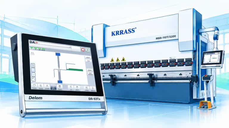
A modern CNC press brake can repeat an axis position with impressive consistency, but repeatability alone does not guarantee a correct part. The controller must know what material is being bent, which punch and die are physically installed, where the backgauge should position the blank, how the bend sequence should progress, and how the ram and compensation functions should behave. The Delem DA-53Tx brings these tasks together in a compact touch-control platform designed for synchronized press brakes.
This guide explains the basic operating workflow of the DA-53Tx for operators, production supervisors, engineers and buyers who want to understand how a graphical CNC controller fits into real press-brake production. It is written as a practical tutorial rather than a replacement for the machine manufacturer’s safety manual. Exact axis availability, hydraulic functions, safety interfaces, crowning configuration and machine parameters depend on the press brake on which the controller is installed.
According to Delem’s official DA-53Tx product information, the controller supports 2D graphical programming, a 15.6-inch high-resolution color TFT, crowning control, servo and frequency-inverter control, USB interfacing and Profile-T offline software. The standard platform is capable of controlling up to four axes. See the official Delem DA-53Tx product page for the current manufacturer specification.
For readers who are still learning the machine itself, KRRASS also recommends reviewing Press Brake Basics for Beginners and the broader Press Brake Bending: Basics & Tips before programming production parts.
Important safety note: A CNC controller does not make an unsafe setup safe. Always follow the press brake manufacturer’s instructions, the tooling load limits, the installed safeguarding system, your factory’s lockout/tagout procedures and applicable local regulations. Never use a tutorial to bypass a light curtain, laser guard, interlock or other point-of-operation safeguard.

What Is the Delem DA-53Tx?
The DA-53Tx is a compact graphical CNC control intended for press-brake applications that need a modern touch workflow without moving into a larger high-end control platform. Its value is not simply that it displays axis numbers. It can connect product geometry, tooling, material data, bend sequencing and machine-axis calculations into a structured program-to-production workflow.
For many job shops, this is an important distinction. A purely numerical controller asks the operator to think primarily in machine coordinates: Y position, X position, retract distance, opening, crowning and other values. A graphical controller allows more of the programming process to begin with the part itself. The operator can create a 2D product profile, select tooling, determine a bend sequence and then let the control generate the corresponding numerical program. Experienced operators can still inspect and modify numerical values where necessary.
The DA-53Tx manual describes two main ways to create a CNC program:
- Create a numerical program directly, step by step.
- Create a 2D product drawing, define tooling and bend sequence, and generate the numerical program from the graphical workflow.
These two methods are useful for different production environments. Direct numerical programming can be fast for simple, familiar parts, but the manual explicitly notes that a manually entered numerical program does not provide the same graphical collision-check workflow. Graphical programming is therefore particularly useful when the part has several bends, when flange orientation changes during production, or when an operator needs a clearer visual representation of the bending process.
DA-53Tx core specification at a glance
| Item | DA-53Tx information | Why it matters in production |
|---|---|---|
| Display | 15.6-inch high-resolution color TFT | Provides space for graphical product, tooling and production views |
| Resolution | 1366 × 768 pixels | Supports clear visualization of geometry and operating data |
| Touch interface | Industrial PCT multi-touch | Enables direct touch navigation and graphical interaction |
| Axis capability | Up to 4 axes standard | Suitable for common synchronized press-brake configurations; actual axes depend on machine configuration |
| Programming | 2D graphical product and tool programming | Reduces dependence on purely numerical programming |
| Crowning | Crowning control supported | Helps compensate for deflection across the bending length when the machine is equipped accordingly |
| Drive integration | Servo and frequency-inverter control | Supports common modern press-brake motion architectures |
| Data exchange | USB standard | Useful for product/tool backup and data transfer |
| Networking | Available depending on configuration | Can support factory data workflows |
| Offline programming | Profile-53TL / Profile-T family support depending on configuration/version | Allows programming work to be moved away from the machine |
The specification above should be treated as controller capability, not a guarantee that every DA-53Tx-equipped press brake has every option. For example, the controller may support an axis or interface that is not physically installed on a particular machine. Always compare the controller configuration with the machine quotation, electrical drawings and actual hardware.
KRRASS maintains a broader comparison of common controllers in Press Brake CNC Control Systems, which is useful when evaluating whether DA-53Tx, DA-58Tx or another controller better matches a production requirement.
Understand the DA-53Tx Workflow Before Touching the Program
A common beginner mistake is to open the controller and immediately start changing numbers. A better approach is to understand the data chain.
A press-brake program is built on assumptions. The controller assumes that the material record represents the actual sheet. It assumes the selected punch and die represent the tools mounted on the machine. It assumes the machine geometry and axes are correctly configured. It assumes the operator has selected a bend sequence that can physically be performed. If any of these assumptions are false, the calculated program can be internally consistent and still produce a bad part—or create a collision risk.
The DA-53Tx workflow can be summarized as:
Material data → product geometry → tooling → bend sequence → numerical CNC program → Auto production → measured result → correction
The Delem manual presents the graphical product workflow in essentially the following order:
- Open Products and create a new product.
- Enter product properties and create the 2D profile in Drawing.
- Verify or modify the tool setup in Tool Setup.
- Determine the bending order in Bend Sequence.
- Review or modify the numerical values in Program if required.
- Enter Auto, verify the setup, start the machine and produce the part.
This sequence is worth learning because the navigation modes are not isolated screens. They represent stages of the same manufacturing problem.
The Main DA-53Tx Modes Explained
The controller organizes major functions into navigation modes. Exact appearance can vary with software version and machine integration, but the underlying logic is consistent.
| Mode | Main purpose | Typical operator question |
|---|---|---|
| Products | Create, find, select and manage products/programs | “Which part am I going to make?” |
| Drawing | Create or edit the 2D product geometry | “What does the finished profile look like?” |
| Tool Setup | Define the physical punch/die arrangement | “Which tools are installed and where?” |
| Bend Sequence | Determine and simulate bend order | “Which bend should be made first, second and so on?” |
| Program | Review/edit numerical CNC values | “What machine values will be used for each bend?” |
| Auto | Execute the active program in production | “How do I run this part repeatedly?” |
| Manual | Program and execute one independent bend | “How do I test or make a single bend?” |
| Settings | Materials and user/programming preferences | “What material properties and user settings are active?” |
| Machine | Tool libraries, machine-related settings, backup and system information | “What machine/tool data is available?” |
The distinction between Auto and Manual deserves special attention. Manual mode is not simply “Auto mode with fewer features.” The manual describes it as an independent production mode used for one bend, testing and calibration. Auto mode, by contrast, executes the active product program bend by bend.
Preparation: What Must Be Correct Before Programming
Good CNC programming begins before the first screen entry. The controller cannot inspect the material certificate, measure the sheet thickness, confirm the punch is fully clamped or notice that a damaged die segment has been installed. Those remain operator and process responsibilities.
Before creating a program, confirm the following.
Confirm the material
Identify:
- material family and grade;
- actual sheet thickness;
- blank dimensions;
- rolling direction when relevant;
- surface-protection requirements;
- expected tensile/yield behavior;
- drawing revision.
The DA-53Tx uses material data in bending calculations. The supplied Delem manual includes default/reference material-property examples such as steel, aluminum, zinc and stainless steel, with tensile strength, E-modulus and strain-hardening values. These are useful for understanding what the control expects, but production should use material data appropriate to the actual grade and your machine manufacturer’s setup.
For example, the manual lists representative tensile-strength values of approximately 470 N/mm² for steel, 250 N/mm² for aluminum, 200 N/mm² for zinc and 750 N/mm² for stainless steel. These should not be treated as universal values for every alloy or grade. Stainless steels, structural steels and aluminum alloys can vary substantially. The correct lesson is that material properties matter to the calculation.
Confirm the tooling
The controller’s tool library must match the physical tools. Verify:
- punch type and angle;
- punch tip radius;
- punch height;
- die type and angle;
- V-opening;
- die height;
- tool segment arrangement;
- load rating;
- orientation;
- clamping and seating.
If the program says a 16 mm V-die is installed while the machine actually has a 24 mm V-die, the calculated bending behavior, required force and geometry can differ. A CNC cannot compensate for incorrect source data.
For a deeper explanation of punch and die selection, see the KRRASS Press Brake Tooling Guide and Press Brake Tooling Basics.
Confirm the machine and safeguarding condition
Before motion, check:
- no active machine or controller alarm;
- axes are referenced as required;
- tooling is securely clamped;
- backgauge fingers are clear of tooling and workpiece collision zones;
- crowning system is operational if used;
- hydraulic/servo system is ready;
- guards, laser protection or light curtains are active and correctly set;
- work area is clear;
- part support is adequate;
- the operator understands emergency-stop locations.
A useful rule is: software verification comes after physical verification, not instead of it.
Creating or Selecting a Product
The Products mode is the practical starting point for most jobs. Existing products can be selected from the library, while a new part can be created as either a graphical product or, depending on workflow, a numerical program.
The manual identifies product status indicators that help the operator understand what data exists:
- P: the product has a CNC program but no drawing;
- 2D: the product has a 2D drawing but no CNC program;
- P2D: the product has both a 2D drawing and a CNC program.
This is more useful than it first appears. In a busy shop, it tells an operator whether a stored job contains the graphical source data needed for visual editing or only the numerical production program.
Selecting an existing product
For repeat production:
- Open Products.
- Search or scroll to the required product.
- Tap the product to load it.
- Verify the product ID and description.
- Review the tooling and material rather than assuming the previous physical setup is still on the machine.
- Enter the appropriate mode—Tool Setup, Bend Sequence, Program or Auto—depending on what needs verification.
The DA-53Tx includes a live-search function for lists such as products, tools and materials. Entering part of an ID filters the displayed items. This is particularly useful when the controller contains hundreds of repeat jobs.
Creating a new product
For a new graphical part:
- Open Products.
- Select New Product.
- Enter a clear product ID.
- Add a description if your shop uses descriptions for revision, customer or part identification.
- Confirm product properties.
- Continue to Drawing.
Use a naming convention that works on the shop floor. A technically perfect program named “TEST2-FINAL-NEW” becomes a production-management problem six months later. Part number, revision and a short identifier are usually more useful.
Drawing a 2D Product Profile
The DA-53Tx graphical workflow allows the operator to create a 2D product profile using touch interaction. The Delem manual describes a combination of sketching and value setting.
Sketching establishes the basic profile. Exact dimensions and angles can then be entered numerically. This combination is efficient because it separates shape creation from precision entry: the operator can quickly define the direction of each flange and then make the geometry exact.
A practical drawing workflow
Assume a simple Z-shaped bracket with three flanges and two 90-degree bends.
- Begin with the first line representing the first flange.
- Add the next line in the direction of the second flange.
- Add the final line for the third flange.
- Select each length and enter the drawing dimension.
- Select each angle and enter the required value.
- Check that bend directions match the engineering drawing.
- Use zoom and fit-to-screen functions to inspect the complete profile.
The manual notes that touch gestures can be used for zooming and panning, while a fit-to-screen function can bring the complete geometry back into view.
Why the drawing should match design intent
The graphical model is not decorative. It influences blank-length calculation, bend sequencing, collision visualization and generated CNC values. If a flange is drawn in the wrong direction or an angle is entered using the wrong convention, the downstream program may also be wrong.
Before continuing, compare the screen profile with the part drawing and ask:
- Are all flanges present?
- Are lengths correct?
- Are bend angles correct?
- Are bend directions correct?
- Is sheet thickness correct?
- Is the material correct?
- Does the profile represent the intended finished part?
For complex jobs, a second-person check can prevent expensive scrap.
Setting Up Punches and Dies
Once the product geometry exists, the next step is to make the virtual tooling match the real machine.
In Tool Setup, the operator can select punches and dies from the tool library and define the setup. The Delem manual specifically describes Select Punch and Select Die functions for changing the active tools.
This stage matters because tool geometry is central to both bend feasibility and collision analysis.
Tool data that should be checked
| Tool parameter | Why it matters |
|---|---|
| Punch angle | Affects clearance and compatibility with the bend |
| Punch radius | Influences inside radius, marking and forming behavior |
| Punch height | Affects machine/tool geometry and collision model |
| Punch shape | Gooseneck or special profiles can provide flange clearance |
| Die angle | Must be compatible with the process and punch |
| V-opening | Strongly influences air-bend force, radius and minimum flange |
| Die height | Affects setup geometry |
| Segment length/position | Must match where the part will be bent |
| Tool load rating | Prevents overload and tool failure |
KRRASS’s tooling guidance emphasizes that tooling is part of the bending system, not an accessory selected independently after the machine. The controller, machine tonnage, V-opening, material, bend length and tooling load rating must all agree.
Do not confuse the library with the machine
A common shop-floor failure is to select the correct tool on the screen but leave a different tool on the machine. Another is to physically change tooling but forget to update the controller.
Adopt a two-way verification habit:
Screen → machine: “Is the physical tool the one shown in the program?” Machine → screen: “Does the controller record accurately describe the tool I can see and measure?”
This habit is simple, but it prevents a large class of setup errors.
Determining the Bend Sequence
After the tool setup is available, Bend Sequence is used to determine the order in which the bends will be formed.
Bend order matters because every bend changes the shape of the workpiece. A flange that is easy to form while the blank is flat may become impossible after another flange is bent. The part can collide with the punch, die, ram, machine frame or backgauge. It can also become difficult or unsafe for the operator to support.
The DA-53Tx graphical workflow helps the operator visualize the product with the machine and tools. The manual describes manual bend-sequence determination, collision visualization, free tool selection, blank-length computation, bend simulation and programmable finger positions as part of this workflow.
Reading the graphical bend-selection feedback
In the manual bend-selection workflow, possible bends are visually identified. The manual describes:
- green indications for bends that can be performed without a detected collision;
- red indications for bends that result in a detected collision;
- yellow indications where an orientation change or similar action may be required.
Treat this as a planning aid, not permission to stop thinking. A controller model cannot represent every real-world situation: loose tooling, unusual part support, human hand position, temporary fixtures, material sag, damaged tooling or a machine modification may not be included in the simulation.
A practical bend-sequence strategy
When several sequences appear possible, consider:
- Collision clearance — can the part clear the punch, die and machine?
- Backgauge contact — is there a stable surface for gauging each bend?
- Part handling — can the operator safely rotate and support the part?
- Accuracy chain — which bends establish dimensions used by later bends?
- Tooling changes — can the job remain in one setup?
- Surface protection — will an earlier bend create scratching or marking risk?
- Large flange behavior — will a flange whip upward or require support?
- Repeatability — can the sequence be executed consistently by different operators?
The best sequence is not necessarily the one with the fewest screen steps. It is the one that is safe, repeatable and dimensionally robust.
How the DA-53Tx Generates the CNC Program
When the graphical product and bend sequence are complete, the controller can generate the numerical program.
According to the Delem manual, the system can automatically calculate or derive values including:
- necessary bending force;
- Y-axis position;
- decompression;
- X-axis position;
- X-axis retract;
- Y-opening;
- R-axis values where configured;
- Z-axis values where configured.
The exact axes available depend on the machine configuration.
This automatic generation is one of the main advantages of graphical programming. The operator does not have to derive every machine coordinate from scratch. However, “automatic” does not mean “unreviewed.” The generated program should be checked before production.
Understanding the Most Important Program Parameters
A DA-53Tx-equipped press brake can expose different parameters depending on machine configuration. The following concepts are fundamental.
Y axis: bending depth / ram position
On a synchronized hydraulic press brake, Y1 and Y2 typically represent the left and right ram/cylinder positions. The controller coordinates these axes to achieve the programmed bend.
Small changes in Y position can produce meaningful angle changes, especially in thin sheet. This is why angle correction should be deliberate and based on a measured test bend rather than random adjustment.
X axis: backgauge depth
The X axis controls the front-to-back position of the backgauge. It establishes where the blank is positioned relative to the bend line.
If the flange dimension is wrong while the bend angle is correct, the first diagnostic question is often whether the blank was properly seated against the fingers and whether the X value matches the intended geometry.
R axis: backgauge height
Where fitted, the R axis moves the backgauge fingers vertically. This is useful when the gauging point changes height between bends or when the workpiece geometry requires a different finger level.
Z axes: lateral finger positioning
On machines equipped with powered Z axes, the backgauge fingers can move laterally along the machine. This can reduce manual finger repositioning and support different part widths or staged tooling layouts.
Retract
Backgauge retract moves the gauge away during part forming when necessary to avoid trapping, scraping or collision as the flange rotates.
Too little retract can interfere with the workpiece. Excessive retract can add unnecessary motion and cycle time. The correct value depends on part geometry.
Y opening
The opening value determines how far the ram returns after a bend. A larger opening can make it easier to remove or rotate a deep part, but increases cycle time. A smaller opening can improve productivity when the geometry allows safe handling.
Decompression
After forming pressure, controlled decompression helps manage the transition out of the loaded condition. Machine builders tune these behaviors according to hydraulic architecture.
Crowning
During bending, the ram and bed can deflect under load, causing angle variation along a long bend. A crowning system compensates for this behavior. The DA-53Tx supports crowning control when integrated with a compatible machine.
Crowning should not be used to hide unrelated problems such as wrong tooling, uneven material thickness, damaged tools or poor alignment. It is compensation for system deflection, not a universal “make the bend accurate” slider.
Numerical Programming: When and Why to Use It
The Program mode gives access to numerical values for the active product. Operators can create a numerical program directly or inspect/edit a program generated from the graphical workflow.
Direct numerical programming is useful for:
- simple one- or two-bend parts;
- experienced operators who know the machine well;
- quick test pieces;
- legacy jobs already documented in machine coordinates;
- situations where a full graphical product is unnecessary.
However, the Delem manual makes an important distinction: when a program is entered manually, the operator is responsible for the values and does not benefit from the same graphical collision-check path used to generate a program from a 2D bend simulation.
For a new operator, graphical programming is generally the better learning path because it makes the relationship between part geometry and machine motion more visible.
Running a Program in Auto Mode
Once the program is ready, Auto mode is used for production.
The manual states that Auto mode executes the active program bend by bend after the machine is started. It also notes that when a different bending program is selected, the operator must check tools and tool positions. A “check tools” warning may be shown when entering automatic mode.
That warning should be treated as a real production checkpoint, not a message to dismiss automatically.
Recommended first-piece procedure
Before running a batch:
- Load the correct product.
- Verify drawing revision and material.
- Verify actual sheet thickness.
- Verify punch and die against the program.
- Verify tool positions and segmentation.
- Confirm backgauge fingers are safely positioned.
- Review bend sequence.
- Review the first bend’s X, Y and compensation values.
- Confirm safeguarding.
- Run the first part at a controlled pace according to the machine manufacturer’s setup procedure.
- Measure the first bend before completing a large batch.
- Apply correction only after identifying the source of error.
- Complete and inspect the first finished part.
- Release the program for repeat production only when the first article is acceptable.
Step mode for controlled execution
The DA-53Tx manual notes that Auto mode can use a step mode so that bends are started separately. This is useful during first-piece verification because it allows the operator to inspect the part and orientation between steps rather than treating the complete sequence as a black box.
Selecting a bend in Auto
The active product and bend sequence are displayed in Auto mode. A bend can be selected from the available bend selector, allowing production to begin from a chosen bend where the machine configuration and operating procedure permit it.
Use this capability carefully. Starting in the middle of a sequence assumes the physical workpiece is already in the state expected by that bend.
Manual Mode: Single Bends, Testing and Calibration
Manual mode is designed for a single independent bend. The Delem manual specifically describes it as useful for testing, calibration and single-bend work.
This makes Manual mode valuable for:
- checking a newly installed tool set;
- performing a controlled test bend;
- investigating material springback;
- verifying a simple one-bend part;
- machine setup and calibration procedures performed by qualified personnel.
The manual also notes that current Y and main X positions are visible at the top of the Manual screen, with other axes and functions listed below. Highlighted axis values can indicate that reference markers have been found and the axes are positioned relative to their programmed values.
Manual mode should not be confused with manually jogging into an unsafe situation. All normal guarding and setup requirements remain in force.
Performing a Test Bend and Correcting the Result
Even with accurate controller data, a first test bend is normal practice. Real material varies. Sheet thickness can differ within tolerance, tensile properties can vary by batch, rolling direction can influence behavior, and tooling wear changes the physical system.
A disciplined correction process is:
Program → bend → measure → diagnose → correct → verify
Do not jump directly from “the angle is wrong” to “change Y.” First determine what is wrong.
If the angle is wrong across the whole part
Check:
- material grade;
- actual thickness;
- correct punch/die;
- V-opening;
- programmed material;
- bend method;
- angle correction;
- Y-depth calculation.
If the setup is correct and the error is consistent, an angle/depth correction may be appropriate.
If the angle varies from left to right
Check:
- tooling alignment;
- tool wear/damage;
- material thickness variation;
- load distribution;
- crowning;
- ram/bed condition;
- machine calibration.
Do not use a global angle correction to solve a left-to-right consistency problem.
If flange length is wrong but angle is correct
Check:
- X-axis value;
- blank size;
- whether the part was firmly seated against the fingers;
- finger position;
- drawing dimension convention;
- bend allowance/deduction assumptions;
- whether the gauging edge is straight and suitable.
If the part collides during rotation
Stop and reconsider the bend sequence, tooling, gauge retract and handling plan. Do not “work around” a collision by placing hands in an unsafe position.
Bending Data: Useful Engineering Relationships
The DA-53Tx performs calculations based on configured machine and material data, but operators benefit from understanding the engineering relationships behind those numbers.
V-die opening and material thickness
For air bending, a common shop starting point for mild steel is a V-opening around 6–10 times material thickness, with approximately 8× thickness often used as a practical rule of thumb for general work. This is not a universal law. Required inside radius, minimum flange, material type, tool availability and tonnage can change the selection.
| Sheet thickness | Example 8× V-opening starting point |
|---|---|
| 1.0 mm | 8 mm |
| 1.5 mm | 12 mm |
| 2.0 mm | 16 mm |
| 3.0 mm | 24 mm |
| 4.0 mm | 32 mm |
| 6.0 mm | 48 mm |
These values are illustrative starting points, not a tooling prescription. Always check the tooling manufacturer’s load chart and the part requirements.
Why a wider V-opening reduces force
In air bending, a wider die opening increases the lever arm over which the sheet bends, generally reducing required force. However, it also tends to increase the natural inside bend radius and the minimum flange requirement. Tool selection is therefore a tradeoff among force, radius, flange geometry and surface quality.
Springback
After the load is removed, the material elastically recovers and the angle opens slightly. Higher-strength materials and some stainless steels can show greater springback than mild steel. The controller can help manage the programmed bend, but a measured test bend remains important when material behavior is uncertain.
Bend allowance and blank length
The flat blank is not simply the sum of finished flange dimensions because material stretches and compresses around the bend. Bend allowance and bend deduction methods account for the neutral-axis behavior.
This is one reason graphical programming is valuable: when geometry and material data are correct, the controller can calculate blank-related values as part of the product model rather than forcing the operator to manage every value separately.
A Complete Example: Programming a Simple Two-Bend Bracket
Consider a generic mild-steel channel bracket:
- material: mild steel;
- thickness: 2.0 mm;
- finished profile: 25 mm flange + 100 mm web + 25 mm flange;
- two 90-degree bends;
- bend length: 500 mm;
- air bending;
- suitable punch and V-die selected according to the actual tooling chart.
This example explains workflow, not production-ready dimensions.
Step 1: Verify material and drawing
Confirm that the physical blank is the intended material and thickness. Confirm whether the 25 mm and 100 mm dimensions are inside, outside or otherwise defined on the drawing.
Step 2: Create the product
Open Products → New Product. Enter a meaningful product ID such as BRACKET-025-100-R1.
Step 3: Draw the profile
Create the three-line channel profile. Enter the exact flange/web dimensions and two 90-degree bends.
Step 4: Select tools
Open Tool Setup. Select the punch and die that physically match the machine setup. For 2 mm mild steel, a 16 mm V-opening may be a common starting point under the 8× rule, but the actual choice must be checked against required radius, flange size, force and tooling data.
Step 5: Determine bend sequence
Open Bend Sequence. Evaluate whether either flange can be bent first without creating a collision for the second bend. For a symmetrical simple channel, either sequence may be possible, but the controller simulation and real tooling clearance should be checked.
Step 6: Generate and review the program
Review X positions, bend angles, Y calculations, opening, retract and compensation values.
Step 7: Run a first piece
Enter Auto, verify tools and safeguards, and use controlled/step execution for the first part.
Step 8: Measure
Check:
- both bend angles;
- web width;
- flange dimensions;
- parallelism;
- surface marking.
Step 9: Correct systematically
If both angles are 91.0° instead of 90.0°, and the setup/material are verified, apply the appropriate angle/depth correction according to the machine configuration. If one end is 90.0° and the other is 91.5°, investigate crowning/alignment/material consistency rather than applying a simple global correction.
This diagnostic mindset is what turns a CNC controller from a number-entry device into a process-control tool.
Tool Libraries: Why Accurate Data Saves Setup Time
A well-maintained tool library can substantially improve programming efficiency. If the tool geometry in the controller is accurate, the operator can reuse proven tooling records instead of recreating them for every part.
A good tool-library management practice includes:
- unique tool IDs;
- verified dimensions;
- clear punch/die descriptions;
- removal or archival of obsolete records;
- consistent naming across machines where possible;
- inspection after tool repair or regrinding;
- controlled editing permissions.
If a tool is reground and its height changes, the library may need updating. The controller is only as accurate as the data provided to it.
Material Libraries: Standardize What Operators Use
Material libraries are equally important. Avoid creating multiple ambiguous records such as STEEL, STEEL2, NEWSTEEL and STEEL-FINAL.
A more controlled scheme might include material family, grade and thickness-independent properties where appropriate, for example:
S235JRS355304-SS316L-SS5052-H326061-T6
The actual structure depends on the controller configuration and company standards.
The purpose is not administrative neatness for its own sake. Material properties influence bending calculations. Standardized records make it easier to reproduce a successful job months later.
Backup and Data Transfer
The DA-53Tx supports external storage through USB, and depending on configuration can support network-based data handling. The manual describes external storage as a way to back up product and tool files and exchange data between Delem controls.
A production shop should treat controller data as manufacturing data, not disposable machine memory.
Recommended backup policy:
| Data | Recommended practice |
|---|---|
| Product programs | Back up after approved production programs are created or revised |
| Tool library | Back up after verified tooling changes |
| Material library | Back up after controlled property changes |
| Machine-specific configuration | Service-level backup according to machine builder instructions |
| Offline programs | Store under revision control on the company network |
| USB transfer | Use controlled, malware-scanned media where factory IT policy requires it |
A controller replacement or storage failure is much less disruptive when the factory has a current, documented backup.
Common DA-53Tx Operating Mistakes
Mistake 1: Trusting the program without checking the physical tools
The screen can show a correct setup while the machine contains a different die. Always verify both.
Mistake 2: Editing machine values before verifying material
An operator sees a 1-degree angle error and changes correction, but the real problem is that the batch is 1.9 mm instead of the assumed 2.0 mm or is a different grade.
Mistake 3: Ignoring the bend sequence simulation
A program may calculate valid axis positions but still create a handling or clearance problem. Use the simulation and then verify the real setup.
Mistake 4: Starting a repeat job without checking tooling
The Delem manual explicitly calls for tool verification when a different program is selected. Repeat program does not mean repeat physical setup.
Mistake 5: Using excessive Y opening
A large return opening may feel safe but can unnecessarily lengthen every cycle. Optimize only after confirming that the part can be safely removed and rotated.
Mistake 6: Using too little opening
The opposite problem is more serious: a part may strike tooling or become difficult to remove. Cycle-time optimization must never compromise clearance and safe handling.
Mistake 7: Correcting a crowning problem with global angle compensation
If the center and ends bend differently, diagnose distribution and crowning. A global correction shifts the entire part and may leave the variation unchanged.
Mistake 8: Poor product naming and revision control
Operators can manufacture an obsolete revision perfectly. CNC accuracy does not protect against document-control mistakes.
Mistake 9: Treating collision visualization as a complete safety system
Graphical collision checking is a programming aid. It does not replace physical guards, safe work methods or operator awareness.
Mistake 10: Changing service or machine parameters without authorization
Machine-level parameters can affect synchronization, limits and safety-related behavior. Only qualified personnel should change protected configuration according to the machine builder’s documentation.
Troubleshooting Table
| Symptom | Likely areas to check | Recommended response |
|---|---|---|
| Bend angle consistently too open | Material, thickness, tooling, Y/angle correction | Verify inputs, make a measured test bend, then correct |
| Bend angle consistently too closed | Material, thickness, tooling, Y/angle correction | Verify inputs before reducing penetration |
| Angle varies along bend length | Crowning, tool alignment, material variation, machine condition | Diagnose distribution; do not rely on global correction |
| Flange too long/short | X position, blank size, gauging contact, drawing convention | Verify gauge and measurement reference |
| Backgauge interferes with part | Retract, R/Z position, sequence, finger location | Stop and revise setup/program |
| Part collides with tooling | Bend order, punch profile, die, orientation | Re-run sequence planning and consider alternate tooling |
| Program looks correct but part is wrong | Physical setup differs from stored data | Compare material and tools screen-to-machine |
| Repeat part suddenly changes | Material batch, tool movement/wear, calibration, setup | Identify what changed before editing the program |
| Cannot find product | Search filter, directory, product ID | Use live search and verify storage location |
| Axis/reference warning | Machine referencing or hardware state | Follow machine builder procedure; do not bypass alarms |
Productivity Tips for Daily DA-53Tx Use
Build reusable, verified libraries
Accurate material and tool libraries shorten setup time and reduce repeated data entry.
Use graphical programming for complex parts
The more bends and orientation changes a part has, the more valuable visual sequencing becomes.
Keep numerical knowledge
Graphical programming does not eliminate the need to understand X, Y, R, Z, retract, opening and crowning. Skilled operators use the graphics to plan and the numerical data to diagnose.
Standardize first-piece inspection
Create a short checklist for angle, flange dimensions, overall dimensions, surface quality and drawing revision. A five-minute controlled first article can prevent a batch of scrap.
Save proven programs, not experiments
Once a part is approved, store the proven values under a controlled revision. Avoid overwriting production programs casually during troubleshooting.
Use offline programming where it adds value
When many jobs must be prepared, offline programming can move part of the programming workload away from the machine, allowing the press brake to remain productive. Verify that the offline software version and machine configuration correspond to the target controller.
DA-53Tx for Press Brake Buyers: What to Specify in an Inquiry
For a buyer, choosing a controller should be based on production needs rather than the controller name alone.
When requesting a quotation for a DA-53Tx-equipped press brake, provide:
- maximum material thickness;
- material types and grades;
- maximum bend length;
- typical part drawings;
- smallest and largest flange dimensions;
- required bend accuracy;
- annual or daily production mix;
- number of setups per shift;
- required backgauge axes;
- tooling standard;
- crowning requirement;
- safety system requirement;
- offline-programming requirement;
- networking/data requirement;
- local electrical standard.
KRRASS offers multiple press-brake configurations, so controller selection should be coordinated with machine tonnage, bending length, backgauge architecture, tooling and production goals. See the KRRASS Press Brake Machine Guide for a broader buying framework.
A DA-53Tx is particularly attractive when a factory wants compact 2D graphical programming and common CNC press-brake functions without requiring the larger display and advanced visualization of higher-tier controls. Whether it is the right choice depends on the parts, operator skill level and automation expectations.
DA-53Tx vs. a Basic Numerical Controller
The practical difference can be summarized as a shift from machine-coordinate-first programming toward part-geometry-first programming.
| Area | Basic numerical controller | DA-53Tx graphical workflow |
|---|---|---|
| Product representation | Primarily numerical bend steps | 2D graphical product profile available |
| Tool representation | Often basic numerical tool data | Graphical tool setup/library workflow |
| Bend sequence planning | Operator experience and manual planning | Graphical bend-sequence simulation |
| Collision awareness | Heavily operator-dependent | Graphical collision visualization available |
| Numerical editing | Yes | Yes |
| Auto production | Yes, depending on controller | Yes |
| Best fit | Simple/repetitive work, experienced numerical programming | Mixed production, multi-bend parts, visual programming preference |
This does not mean a graphical controller automatically makes better parts. A skilled operator with a simple controller can produce excellent work, while incorrect data on an advanced controller can still create scrap. The advantage is that the DA-53Tx provides more structured information for planning, verification and repeat production.
Safety: Controller Skill Must Develop Together With Press-Brake Skill
A press brake creates a severe pinch/crush hazard at the tooling and can also create hazards from moving backgauges, large swinging flanges, heavy tools and unsupported workpieces. Controller training should therefore never be separated from machine-safety training.
Operators should understand:
- point-of-operation hazards;
- safeguarding devices;
- emergency stops;
- safe tool installation;
- tool load limits;
- safe workpiece support;
- backgauge motion;
- pinch points created by part rotation;
- safe handling of small parts;
- lockout/tagout requirements for service and tool-related tasks as applicable.
The exact legal requirements depend on jurisdiction. In the United States, OSHA machine-guarding requirements and recognized machine-specific standards are relevant references; in other markets, local machinery safety legislation and applicable EN/ISO standards may govern. The machine builder’s supplied safety documentation remains essential.
KRRASS’s Press Brake Tooling Guide also discusses tooling-related safety questions, including tool load rating, secure clamping and workpiece support.
Frequently Asked Questions About DA-53Tx Operation
Is DA53TX the same as DA-53Tx?
In search queries and informal writing, users often type DA53TX, DA-53TX, DA53Tx or DA-53Tx. Delem’s official product styling is DA-53Tx. For SEO, it is reasonable to include natural variants in the article while using DA-53Tx as the primary technical name.
Can the DA-53Tx create a program from a 2D drawing?
Yes. The graphical workflow allows a 2D product to be created, tooling to be selected, a bend sequence to be determined and a numerical CNC program to be generated from that information.
Can I program bends numerically without drawing the part?
Yes. The manual describes direct numerical programming as an alternative workflow. However, the operator is responsible for the entered values, and a manually entered numerical program does not use the same graphical collision-check process as a program generated through graphical bend simulation.
How many axes can the DA-53Tx control?
Delem lists the DA-53Tx as standard capable of controlling up to four axes. The actual axes available on a press brake depend on how the machine manufacturer configured the machine.
Does the DA-53Tx support crowning?
Yes, Delem lists crowning control among the DA-53Tx features. The physical press brake must also be equipped with a compatible crowning system.
What is Auto mode used for?
Auto mode runs the active production program bend by bend. It is the normal mode for producing a programmed part.
What is Manual mode used for?
Manual mode is an independent single-bend mode useful for testing, calibration and one-bend operations.
Can I back up DA-53Tx programs?
Yes. USB data exchange is a standard DA-53Tx capability, and the manual describes external storage for product and tool data. Network options depend on configuration.
Why does the controller tell me to check tools?
Because loading a different program does not physically change or verify the tooling. The operator must confirm that the punch, die and positions on the machine match the selected program.
Does collision detection mean the bend is safe?
No. Collision visualization helps identify modeled geometric interference. It does not account for every real-world hazard and does not replace safeguarding, safe handling, tool inspection or operator judgment.
Should I correct every angle error with Y-axis adjustment?
No. First verify material, thickness, tooling and whether the error is uniform along the bend. A left-to-right angle variation, for example, may point to crowning, alignment or material variation rather than a simple global depth error.
What information should I prepare before asking KRRASS for a DA-53Tx press brake quotation?
Provide part drawings if possible, plus material types, thickness range, maximum bending length, required accuracy, production volume, tooling needs, desired backgauge axes, safety requirements and any offline/networking requirements. This allows the controller and machine configuration to be matched to the work rather than selected by model name alone.
A Practical Operator Checklist
Use the following as a compact workflow reminder.
Before programming
- Confirm drawing revision.
- Confirm material and thickness.
- Confirm blank dimensions.
- Confirm the required bending method.
- Confirm available tooling.
During programming
- Create/select the correct product.
- Verify product geometry.
- Select the physical punch and die accurately.
- Determine a collision-free, practical bend sequence.
- Review generated numerical values.
- Check backgauge positions, retract and opening.
Before the first bend
- Verify tooling on the machine.
- Verify tool clamping and load rating.
- Confirm axes are ready/referenced.
- Confirm safeguards.
- Clear the work area.
- Confirm the first bend orientation.
- Use a controlled first-piece procedure.
After the first bend
- Measure angle.
- Measure flange dimension.
- Check surface quality.
- Diagnose before correcting.
- Verify the correction with another controlled bend.
Before batch production
- Complete and inspect the full first article.
- Confirm program revision.
- Save approved corrections.
- Record special setup notes.
- Release the job only when the process is stable.
Conclusion: Use the DA-53Tx as a Process Tool, Not Just a Touchscreen
The Delem DA-53Tx is most useful when the operator understands the complete chain from drawing to finished bend. Its 2D graphical programming, tool setup, bend-sequence simulation, numerical program generation, Auto mode and Manual mode can make press-brake programming clearer and more repeatable, but the controller still depends on correct material data, correct tooling, a mechanically sound machine and disciplined operating practice.
For beginners, the best learning path is to start with simple parts: one bend, then two bends, then a small multi-bend profile. Learn what changes in the physical part when X, Y, tooling, material or sequence changes. Use the graphical interface to understand geometry, and use the numerical views to understand machine motion.
For production managers and buyers, the DA-53Tx offers a practical middle ground: a compact controller with 2D graphical programming and modern touch operation that can support common synchronized press-brake configurations. The correct final machine specification should still be based on the parts you manufacture.
If you are evaluating a press brake with a DA-53Tx controller, KRRASS can configure the machine around your material, bending length, tonnage, tooling, backgauge, crowning and safety requirements. Review the KRRASS press brake range or send representative part drawings and production requirements to obtain a configuration recommendation.
Editorial Reference Notes
This guide was developed from the supplied DELEM DA-53Tx 2D Control Manual V1.8 (V0923), Delem’s current public DA-53Tx product information, and KRRASS press-brake/tooling technical resources. Controller screens and available parameters can vary by software version and machine integration. Always use the documentation supplied with the specific press brake for machine-level operating and safety procedures.
Preview Delem DA-53Tx controller PDF file
DA-53Tx System Introduction Manual_English
Download PDF file
Share