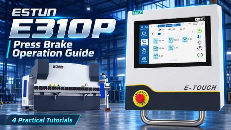
The ESTUN E310P helps operators organize the information needed for everyday press brake work: the tooling installed on the machine, the material being formed, the required bend angle, and the backgauge position. A useful setup brings those details together before the first production part reaches the tools. For a fabrication business, that preparation supports repeat orders, operator training, and more consistent handovers between shifts.
This guide follows the KRRASS E310P demonstration through four practical tasks: adding a die, setting up manual bending, creating a bending program, and adjusting angle compensation. It also explains how those tasks affect production decisions and what buyers should confirm when specifying an E310P-equipped press brake.
The central lesson is straightforward. Build an accurate tool record, enter the correct job information, verify a trial bend, and retain the approved settings. The controller makes these settings easier to manage, while the finished part still needs to be checked against its drawing. If you are evaluating a machine for this workflow, the KRRASS Essential Bend press brake range provides the relevant starting point for discussing capacity, tooling, and controller configuration.
Watch the E310P Video Tutorial
Watch the complete demonstration below, or use the timestamps to return to a specific operation while reviewing the written instructions.
Watch the ESTUN E310P tutorial on YouTube.
| Video time | Tutorial | Main task |
|---|---|---|
| 00:26 | Adding a die | Create and recall a tooling record |
| 00:56 | Setting up manual bending | Enter material, angle, and backgauge settings |
| 01:30 | Creating a bending program | Build, edit, and load a sequence of bends |
| 02:32 | Adjusting bending angle compensation | Measure a trial bend and refine the correction |
What the E310P Offers a Fabrication Workshop
KRRASS lists the E310P with a 10-inch color resistive touchscreen, direct angle programming, a tool library, and a material table. The controller supports X, Y, and R servo axes, together with mechanical or hydraulic crowning control. Its published functions also include USB backup of programs and parameters. These capabilities are described in the KRRASS E310P system introduction.
KRRASS describes the E310P option on Essential Bend as four-axis X/Y/R/C control with bend-depth calculation based on angle, material, thickness, and tooling. The installed functions depend on the machine configuration. A controller specification therefore needs to be read alongside the quotation for the actual backgauge, crowning mechanism, and machine hardware.
For an operator, angle programming provides a familiar starting point because the drawing normally specifies a finished angle. The operator enters the job data and verifies the calculated result with a trial part. Stored tooling records also allow the same die to be selected by its identifier on later jobs, instead of recreating its geometry each time.
The purchasing benefit comes from how these functions fit your work. A workshop with recurring brackets may value quick program recall. A subcontractor changing jobs frequently may place more value on clear parameter entry and an organized tool library. Compare those needs with the options in the KRRASS press brake control system guide before specifying a controller solely by screen size or axis count.
Prepare the Job Before Entering Parameters
Start with the current drawing revision and identify the material grade, thickness, bend angles, flange dimensions, and required tolerances. Check the actual stock as well as the paperwork. A material description such as “steel” does not fully identify its strength or forming behavior, and a previously successful program may need verification when the stock changes.
Confirm the punch and die physically installed on the machine. Check their identification, condition, dimensions, and permitted loading against the job. Tool installation and adjustment should follow the machine manufacturer’s procedure, including the required isolation of hazardous motion. Only trained personnel should operate the machine, with its specified guards and protective devices functioning.
Plan how the operator will support, rotate, and gauge the workpiece. A program can store a sequence of positions, but the operator must still be able to present each bend to the tools without a collision or loss of control. Pay particular attention to short flanges, large sheets, and bends that enclose access to later features.
Agree on the inspection method before the trial. Use an appropriate angle measuring instrument and a suitable method for checking flange dimensions. Record which surfaces define the measurement. Consistent measurement prevents two operators from applying different corrections to the same part simply because they are checking it differently.
Tutorial 1 Adding and Recalling a Die
The first tutorial begins at 00:26. In this context, the die is the lower forming tool. Its record tells the controller which geometry is being used for the bend calculation.
Create the Die Record
- Open Settings, then select Die.
- Select an unused row in the die list.
- Select Edit to open the die editing screen.
- Enter the required values for Height, V-width, Angle, Radius, and SafeZone.
- Check the entries against the actual tooling information, then select Confirm to save the record.
Use the dimensions supplied for the installed tool. Die height describes its vertical geometry, and V-width identifies the opening used for bending. The angle and radius fields describe additional tool geometry required by the control. The meaning and reference points for each dimension must match the applicable controller documentation and tool drawing.
Treat SafeZone as a defined setup parameter. Enter the value specified for the machine and tooling combination; do not guess a clearance or reduce it to make an interrupted operation continue. If the field is unclear, obtain the correct definition from the machine documentation or KRRASS technical support before using the record.
Recall the Correct Tooling
To call an existing die record, select the die selection button and enter the corresponding identification number. Check that the selected record matches the die actually installed. A valid number can still identify the wrong tool, so this comparison should become part of every setup handover.
Keep the tool numbering system simple. For example, the identifier in the controller can match the identifier on the storage rack and setup sheet. If your workshop uses several similar dies, record the opening and other distinguishing dimensions alongside the number. This practice helps a replacement operator select the intended tooling without relying on memory.
Review whether a record is shared by other jobs before changing it. A correction intended for one part should not quietly redefine a physical tool used across many programs. Where possible, maintain a controlled tool register and record who approved a geometry change.
Why Die Data Affects the Result
In air bending, the sheet is supported over the die opening while the punch moves into it. The penetration depth influences the resulting angle. The relationship also depends on the material and tooling, which is why a saved angle cannot be separated from the setup that produced it. TRUMPF’s explanation of bending methods describes this relationship between punch travel, angle, and tool geometry.
For business buyers, this makes tool management a useful demonstration item. Ask the supplier to create a record, recall it in another job, and show how operators verify that the correct die is selected. A clear routine is easier to train and audit than a collection of unlabelled settings.
Use Material and Force Data to Check the Setup
Thickness deserves careful attention because its effect on forming load is substantial. SSAB’s published force-estimation equation includes thickness squared, bend length, and tensile strength, together with a denominator accounting for die width and tool radii. See the bending-force section on page 5 of SSAB’s Bending of Strenx guide, available here as a manufacturer-authored PDF hosted by a fabricator.
The following calculations illustrate that relationship while holding all other inputs constant. They are relative comparisons, not tonnage settings or evidence that a particular tool can accept the changed job.
| Change in one input | Calculation | Estimated force change |
|---|---|---|
| Thickness increases from 2.0 to 2.2 mm | 1.1 multiplied by 1.1 | 21% higher |
| Thickness increases from 2.0 to 3.0 mm | 1.5 multiplied by 1.5 | 125% higher |
| Bend length increases from 1,000 to 2,000 mm | 2,000 divided by 1,000 | 100% higher |
For an actual job, check machine capacity, tooling load limits, material data, and the chosen geometry together. A controller entry alone does not establish that a bend is within the equipment’s permitted loading.
Use this discussion when preparing a quotation request. Give the supplier both the material thickness and the maximum length bent at that thickness. A request stating only “3 mm steel” leaves out information needed to assess capacity. Include the steel grade and intended tooling where known, and ask for a documented review of representative parts.
Tutorial 2 Setting Up Manual Bending
The second tutorial begins at 00:56 and uses the Single panel. This mode provides a practical way to prepare one bend and verify its settings before building a longer sequence.
Enter the Bending Parameters
Open Single and select the material. Enter the sheet thickness, recall the appropriate die, and set the target bend angle. The demonstration uses 90 degrees. Enter the required X-axis value for the backgauge position, then review the complete set of parameters before enabling the machine.
The X-axis setting relates to the position of the backgauge in the front-to-back direction. The finished flange dimension must still be verified on the part. Tool geometry, the selected gauging surface, and the way the part is presented all affect the relationship between a gauge position and the drawing dimension.
Avoid changing multiple fields simply to make a trial part look closer to the drawing. If the angle is wrong, first check the angle-related inputs and measurement. If the angle is correct but the flange dimension is wrong, investigate the gauge reference and X setting. Keeping these checks separate makes it easier to identify which adjustment solved the problem.
Start the Pump and Check the Ram Position
In the demonstration, the operator presses and holds the hydraulic pump start button after entering the job parameters. The control also offers single-pedal and double-pedal modes. Use the mode specified for the machine’s installed foot-control arrangement and approved operating procedure. The labels should not be interpreted as instructions to alter the safety circuit or improvise a different pedal arrangement.
If the screen displays Beam not in UDP, the demonstrated sequence requires the beam, or ram, to return to its upper dead point. With the movement area clear and the machine ready for that operation, press and hold the ram-up control until the required upper position is reached. Follow the machine’s documented procedure if the message remains present.
Once the required conditions are satisfied, the video shows pressing and holding Start to enable the bending operation. Perform the bend through the machine’s configured operating controls and foot-control sequence. Screen activation and the actual forming stroke are distinct parts of the machine’s operating logic.
Inspect the Trial Part
Make the initial trial with suitable material representative of the production job. Measure the bend after the forming load has been released and check the flange dimension against the drawing. For a long bend, take readings at more than one location so a single measurement does not hide variation across the workpiece.
Retain the accepted material, tooling, and correction information with the job. Single mode is especially useful for learning how the setup behaves, but a successful isolated bend does not yet prove that every bend in a completed component will be accessible. That sequence needs its own review when the job moves into a program.
Tutorial 3 Creating and Loading a Bending Program
The third tutorial begins at 01:30. A bending program stores the settings for successive operations so the operator can follow an organized sequence for a part.
Create a New Program
- Open Programs and select New.
- Enter a program name, then select OK.
- Set the parameters for the first bending step.
- Select the plus button at the upper right to add the next step.
- Enter that step’s parameters and repeat the process until the required sequence is complete.
Use a program name that can be connected to the production paperwork. A part number followed by the drawing revision is often more useful than a description such as “bracket.” If operators may use more than one approved tooling arrangement, record that distinction in the setup documentation as well.
Check each step individually. Similar bends can still require different gauge positions, orientations, or correction values. Also review which edge will contact the backgauge at each stage. After an earlier bend changes the shape, the same reference edge may no longer sit against the fingers in the intended way.
Review the Physical Bend Sequence
Before running the program, walk through how the blank will be turned and repositioned. Confirm that the growing shape can clear the punch, die, machine frame, and backgauge. A channel, return flange, or enclosed feature may require a particular order of operations or different tooling access.
A useful setup sheet includes a simple part sketch with numbered bends and the gauging edge identified for each step. This makes the operator’s physical actions easier to match to the stored program. It also gives supervisors a clearer basis for training someone who did not create the original job.
The video demonstrates numerical step creation. Do not assume that a program entered this way has automatically undergone a complete three-dimensional collision simulation. Validate the sequence using the capabilities and procedures supplied with the actual machine.
Delete a Step and Set Repetition
To delete a bend step, select the intended step, press the trash icon at the upper left, and confirm with Yes. Review the remaining sequence afterward. Removing an operation can change which physical bend corresponds to the next displayed step.
The demonstration also uses the repetition icon at the upper left to enter a repeat value. Confirm what that field repeats in the installed software and the selected operating mode. The meaning should be established before treating it as a finished-part quantity or including it in production planning.
Load the Program and Monitor the Current Step
To recall a saved job, open Programs, select the required program, and press Load. Verify the program name and revision before starting. Compare the loaded tooling and material settings with the current setup instead of assuming they remain correct from the previous run.
During operation, monitor CurrStep, the current step indicator. Match it to the bend being presented to the tooling. This check is particularly useful after a pause, a rejected trial part, or a shift change, when an operator could otherwise resume at the wrong operation.
Keep a controlled copy of the approved job information. When using the documented USB backup function, follow the machine’s procedure and identify backups by machine and date. Program storage becomes more valuable when the shop can distinguish an approved production version from an unfinished trial.
Tutorial 4 Adjusting Bending Angle Compensation
The fourth tutorial begins at 02:32. It shows the practical process of making a trial bend, measuring it, adjusting the correction, and testing the result again.
Understand the Measured Error
The target angle in the example is 90 degrees, while the first measured result is 92 degrees. The angle is therefore 2 degrees more open than the target. The useful comparison is between the required finished angle and the measured, unloaded part.
A difference between the programmed angle and the finished angle can arise from the material’s elastic recovery, commonly called springback, as well as setup or material differences. SSAB’s guide to press brake bending explains springback and the role of tooling, material condition, and machine setup. The controller’s calculation is a starting point that must be checked against the actual part.
Follow the Correction Shown in the Video
In this particular demonstration, the existing compensation value is 16. The operator reduces the displayed value to 14, makes another trial bend, and measures again. The stated result meets the required angle.
| Item in the demonstration | Value |
|---|---|
| Target angle | 90 degrees |
| First measured angle | 92 degrees |
| Measured difference | 2 degrees more open |
| Previous compensation entry | 16 |
| Revised compensation entry | 14 |
This is the correction direction shown for the filmed setup. It should not be treated as a universal instruction to subtract every measured angle error. Confirm the correction field, its units, and its direction for the installed controller version and machine configuration. Retain the original value so the change can be reviewed or reversed.
Use another suitable trial piece when checking the adjusted setting. Repeatedly bending the same test area can change its forming behavior and may not represent a fresh production blank. Keep the material and tooling conditions consistent while evaluating the effect of a correction.
Distinguish an Angle Error From Variation Along the Bend
Compare measurements along the bend before choosing an adjustment. If the angle is consistently too open across the part, a general correction may be relevant after the setup has been checked. If the ends and center differ, investigate factors such as tool seating, alignment, loading, and the crowning setup.
Crowning compensates for machine deflection under load. It serves a different purpose from changing the general angle correction for a step. The KRRASS explanation of press brake crowning provides additional context for understanding variation along a long bend. The available adjustment method depends on the machine’s installed crowning system.
Record the accepted correction together with the job and its material details. If a future batch behaves differently, that record helps the operator compare conditions before making further changes. It also preserves the reason for the correction, which is more useful than retaining an unexplained number alone.
Resolve Common Setup Problems Methodically
When a recalled job produces an unexpected result, compare the current conditions with the last approved setup. Start with the program revision, selected die record, actual tooling, material grade, and measured thickness. Correct any mismatch before making compensating changes elsewhere in the program.
If the flange dimension varies while the angle is stable, check how the workpiece contacts the backgauge. Burrs, an unsuitable reference edge, or inconsistent support can prevent the sheet from sitting as intended. Check the physical presentation of the part as well as the programmed X position.
If angle measurements vary from one trial to another, review the measuring method and stock consistency. Check for damaged or contaminated tooling and incomplete seating. Keep a record of what changed between trials. A sequence of unexplained edits makes it difficult to know whether a successful result is repeatable.
If the control does not permit the next operation, read and resolve the displayed condition using the machine documentation. A position message and a safety-related stop require different investigations. Do not bypass a protective device or change restricted machine parameters merely to continue a job.
For a support request, provide the machine identification, controller version where available, active program and step, displayed message, relevant parameters, and clear photographs of the tooling and measured part. This gives the support team useful evidence and reduces the number of questions needed to understand the problem.
Measure the Business Value of Better Setup Control
The most useful commercial measures are those your workshop can record: time to the first accepted part, trial pieces used per setup, rework, and the time needed to restart a repeat job. Compare similar parts and similar operating conditions so a change in product complexity is not mistaken for a controller benefit.
Consider a clearly hypothetical example. A workshop completes six setups per day over 22 working days in a month. If an improved setup routine saves five minutes per setup, the monthly time released is 660 minutes, or 11 hours. This is arithmetic for planning, not a measured E310P performance claim.
Whether those hours become additional output depends on the rest of the factory. Material availability, downstream welding, inspection capacity, and customer demand may limit the benefit. Use your own measured change in setup time when evaluating an equipment purchase, and distinguish available capacity from actual additional sales.
First-part acceptance is another useful measure. Define it consistently, for example as a setup whose first trial part meets all specified checks without correction. Record the same definition before and after introducing a new routine. A small, reliable record of your own jobs is more persuasive than an unsupported claim that a controller improves productivity by a fixed percentage.
Program discipline also supports quotations. When the workshop can retrieve an approved setup and identify how long a comparable job took, the estimator has a better basis for planning repeat work. This does not eliminate material variation or inspection time, but it makes those allowances easier to discuss explicitly.
Specify an E310P Equipped Press Brake for Your Parts
Begin the equipment discussion with representative drawings. Include the longest bend, the thickest material, the shortest flange, and any return feature that restricts tool access. These examples reveal requirements that a general description of the workshop may miss.
Confirm the capacity for the intended combination of material strength, thickness, bend length, and tooling. Also check the working length, opening, stroke, and space needed to handle the component. Nominal tonnage is only one part of the selection.
Ask which axes and adjustments are included in the quotation. E310P controller capability does not mean that every supported axis is fitted to every machine. Confirm the installed backgauge arrangement and whether crowning is provided, how it is controlled, and what the operator can adjust during normal production.
The Essential Bend range uses torsion-bar synchronization and offers different controller and configuration options. If your parts require a different machine architecture or more extensive programming and automation functions, compare the relevant alternatives in the wider KRRASS press brake range. The choice should follow the parts and production requirements.
For a useful acceptance demonstration, ask to see a representative part made from setup through inspection. Include tool selection, parameter entry, the first measured bend, any correction, and program recall. Agree on the drawing tolerances and measuring method in advance so both parties assess the same result.
Discuss operator training, program backup, spare-parts support, and the documentation supplied with the machine. Request the specific machine configuration and applicable safety provisions in writing. These details help the purchasing team compare complete offers and prepare the workshop for installation.
Frequently Asked Questions
Is the E310P Suitable for an Operator Learning Bending
The touchscreen workflow and stored job information can support structured training. A new operator still needs instruction in tooling, workpiece handling, gauging, inspection, and the machine’s safety procedures. Use the four video tutorials as part of supervised training on the actual machine.
Can I Reuse a Program With Different Material
Review and verify the setup whenever the material grade or thickness changes. Keep the original approved program identifiable, check the new job against equipment limits, and measure a fresh trial part before releasing production.
Does Angle Programming Eliminate Trial Bends
Angle programming calculates an initial setting from the entered information. The tutorial itself demonstrates why a measured trial remains useful: the first result is 92 degrees against a 90-degree target. Acceptance depends on the measured part and the drawing requirements.
Is the Die Angle the Same as the Finished Bend Angle
They describe different things. The die angle is part of the tool geometry, while the target angle describes the required part. In air bending, punch penetration also affects the result. Select compatible tooling and enter both kinds of information correctly.
What Should I Send KRRASS for a Recommendation
Send representative drawings, material grades, thicknesses, maximum bend lengths, typical batch quantities, and required tolerances. Identify any difficult flanges or handling requirements. This gives the team a practical basis for discussing capacity, tooling, controls, and the appropriate machine configuration.
Discuss Your E310P Application With KRRASS
Use the video and this guide to define the workflow you want operators to follow. Then review that workflow against your own parts, inspection requirements, and production schedule.
Explore the KRRASS Essential Bend press brake range, or contact KRRASS for an application review and quotation. Include a representative drawing and your material information so the discussion can address the actual bending task.
You can also email [email protected] or contact the team on WhatsApp at +86 189 5208 7956. For further operating guidance, visit the KRRASS tutorials section.
Share