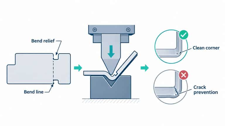
A small slot at the end of a bend can prevent a surprisingly expensive manufacturing problem. Without enough space for the material to deform, the boundary between a bent flange and an adjacent flat region may tear, wrinkle, bulge, or pull a nearby hole out of shape. Adding a relief cut usually costs very little when the blank is already being laser cut, but an incorrectly placed relief can create a new crack starter or weaken a structural part.
These sheet metal bend relief guidelines explain how to decide whether a part needs a relief, how to dimension it, which shape to choose, and how to check the result on an actual press brake. They also address a critical purchasing question: when does a part-design change solve the problem, and when do you need different punches, dies, cutting equipment, or a more capable bending process?
Quick answer: A bend relief is a controlled cutout, usually located where a bend terminates beside an edge, a tab, a cutout, or an unbent section. For conventional sheet-metal work, start with a clearly dimensioned slot whose width and depth are compatible with material thickness, inside bend radius, the flat-pattern geometry, the cutting process, and the fabricator’s validated rules. Do not assume that every material and manufacturer uses the same minimum. Check that the relief actually clears the deformed bend region, that its end geometry does not concentrate excessive stress, and that the finished part still meets strength, appearance, and assembly requirements.
For context, SendCutSend’s bend-relief guide publishes a minimum relief width of half the sheet thickness and a depth calculated from thickness, bend radius, and an additional 0.5 mm allowance under its stated convention. Protolabs’ bend-relief guidance describes a different way of measuring how far a notch extends beyond the end of the bend radius. Fictiv’s fabrication specifications list still another supplier-specific starting point. These references are valuable because they reveal that the measurement datum is as important as the number. A relief depth measured from the theoretical bend line cannot be copied blindly into a drawing that measures depth from the bend tangent or a free edge.

What Is Bend Relief in Sheet Metal?
Bend relief in sheet metal is the deliberate removal of material at a location where a formed region must move differently from the material next to it. Imagine an L-shaped flange that stops partway along a panel. The flange rotates around the bend line, while the neighboring panel must remain flat. Without a small separating cut, material near the stopping point is pulled and compressed in a complicated three-dimensional pattern. A narrow slot lets the two regions deform with less interference.
A relief is not a guarantee against cracking. It does not remove the need to select a bendable grade, an appropriate inside radius, a compatible die opening, or a sound bend orientation. Instead, it handles a local geometric constraint that an otherwise correct bending process may not overcome.
The term is sometimes used loosely to describe several different features. A bend-end relief separates a terminating bend from the unbent sheet. A corner relief provides space where two or more bends approach the same corner. A hole or feature relief helps keep mounting or locating features outside the most severely deformed material. A rip or seam gap permits a folded enclosure to close without unwanted overlap. Each feature removes material for a different geometric reason, so its inspection criteria should not automatically be the same.
The distinction also matters to a purchasing engineer. A bracket with a small relief can often be produced by ordinary flat laser cutting followed by air bending. A part with multiple intersecting folds, a sealed corner, a visible cosmetic face, and no allowable opening may instead require welding, redesigned flange sequencing, special forming tools, or a different manufacturing method.
Why Sheet Metal Tears, Bulges, or Distorts Near a Bend
A press brake typically forms a bend by driving a punch against sheet metal supported by a lower die. The inner part of the curve is primarily compressed; the outer part is primarily stretched. The material between these regions experiences a strain gradient, and the effective neutral-axis location varies with the forming method, geometry, and material. This is why the flat length cannot be calculated from outside dimensions alone.
In the middle of a long, uninterrupted bend, material can distribute deformation along a relatively consistent section. At the end of that bend, the stress field changes. A nearby straight edge, corner, tab, or hole may not be free to follow the bending material. Deformation becomes less uniform, and several visible failures can result.
Tearing or cracking often begins at an abrupt inside corner or a cut edge near the transition from bent to unbent material. Bulging occurs when material that cannot move into the intended geometry is pushed sideways or upward. Twisting and warping appear when the geometry is asymmetric or one region resists rotation more than another. Hole elongation occurs when a precision feature sits partly in the bend-affected zone. A sharp protrusion can remain where a small unrelieved fragment is dragged during forming.
The location and appearance of the defect are diagnostic clues, not definitive proof of a single cause. Cracks distributed along the outside of a bend may indicate inadequate radius, poor bend direction, excessive hardness, or damaged edges; adding a notch at the bend end will not cure the whole bend. A single crack starting precisely where a short bend meets a stationary edge points more directly toward a missing, shallow, or poorly finished relief.
Protolabs’ sheet-metal fabrication guidelines explicitly discuss feature deformation near bend lines and the use of local material relief to isolate critical areas. In that context, the relief is part of a wider design-for-manufacturability decision, not a substitute for inspection or material selection.
Where a Relief Is Needed—and Where It Is Not
Not every bend should receive a notch. Cutting unnecessary reliefs increases blank-program complexity, creates edges that may require finishing, and can reduce strength or sealing performance. The correct question is whether the bend is geometrically restrained near its termination.
Typical situations that merit review include a partial-length flange along a panel, a tab cut into a larger sheet, a U-shaped bracket whose bends meet adjacent material, a box corner with intersecting flanges, a narrow web between a bend and a slot, and a housing with a mounting hole close to a formed edge. A tightly specified electrical enclosure may also need clearance to prevent corner interference when the folds close.
By contrast, a full-width flange with free ends and no nearby interacting features may form correctly without a separately drawn relief. A tiny cosmetic notch added to such a part may have no practical benefit. A hemming operation has a different deformation pattern from a conventional 90-degree air bend and must be reviewed under its own process rules. A welded and sealed box corner can also justify a different relief form from an open ventilation bracket.
An effective drawing review asks four questions. Does the bent section need to move independently of nearby material? Is the planned opening wide and deep enough after realistic manufacturing tolerances? Does the removal of material compromise the part’s service requirements? Can the proposed machine and tooling reach the bend without collisions or loss of support? The answers are interdependent. A perfect relief on paper is not useful if the part collides with the punch halfway through the required sequence.
Bend-End Relief, Corner Relief, and Rip Gap Compared
| Feature | Primary purpose | Typical location | Common design mistake | Inspection focus |
|---|---|---|---|---|
| Bend-end relief | Isolate the end of a flange from adjacent flat material | Termination of a bend line near a sheet edge or tab | Slot ends inside the deformed bend region | Cracks, bulges, actual slot depth |
| Two-bend corner relief | Allow adjacent flanges to fold without corner interference | Intersection of two bends | Corners overlap or create a sharp, fragile point | Flange clearance, assembled corner shape |
| Three-bend corner relief | Accommodate complex intersecting folds | Three converging bends | Applying a simple two-bend rule to three-way movement | Collision, local strain, material remnants |
| Rip or seam gap | Separate edges that must move or close independently | Enclosure seams or folded sections | Insufficient gap after forming or coating | Seam clearance and final fit |
| Feature-isolation cutout | Protect a nearby hole, slot, or insert zone | Near a mounting feature or formed lip | Removing too much material around a fastener | Feature geometry and residual edge distance |
The Autodesk Fusion sheet-metal rule reference distinguishes ordinary bend reliefs from two-bend and three-bend corner reliefs. That separation is a useful CAD-modeling discipline: do not let one global relief parameter control features with genuinely different functions.
Sheet Metal Bend Relief Guidelines: Critical Dimensions and Drawing Conventions
Before choosing a slot size, define the variables and where they are measured. In a fabrication drawing, an unlabeled relief depth is an invitation to error.
Let t denote actual sheet thickness; Ri denote the intended inside bend radius; w denote the relief opening width in the flat pattern; d denote relief depth measured from a specified datum; and c denote any additional depth or clearance required beyond the geometric bend-affected zone. The bending angle, the intended bend direction, and the blank edge geometry must also be known.
There are at least three possible depth datums in practice: the theoretical centerline of the bend in the flat pattern, the tangent boundary of the formed region, and the original sheet edge from which the notch is cut. These are not equivalent. If a supplier says the notch should reach 0.5 mm beyond a defined bend boundary, that does not mean the entire notch depth should equal 0.5 mm. Similarly, a formula involving t + Ri may represent an engineering model measured from a certain line, not an absolute CAD slot length from every external edge.
For consistent use of these sheet metal bend relief guidelines, a robust production print should show the notch endpoints relative to a named drawing datum or dimensioned bend line, the flat-pattern width, its end radius if applicable, and the accepted tolerances. For a stamped or laser-cut blank, verify how the cut width, kerf compensation, material thickness variation, and later finishing affect the opening that is actually delivered.
What Different Published Guides Recommend
| Reference | Published width guidance | Published depth guidance | How to use it |
|---|---|---|---|
| SendCutSend | At least 0.5t | t + Ri + approximately 0.5 mm, measured from the supplier’s stated bend-line convention | A process-specific starting rule; confirm its drawing datum |
| Protolabs bend-relief guidance | At least 0.030 in (0.762 mm) | Extend at least 0.015 in (0.381 mm) beyond the end of the bend radius, per the illustrated convention | Useful for understanding clearance beyond the actual bend region |
| Fictiv sheet-metal specifications | At least t or 0.030 in, whichever is greater | At least 1.5t under its published specification | More conservative for width in many thicknesses; check exact part geometry |
| Actual contracted fabricator | Per validated tooling, material, laser/stamp process, and acceptance criteria | Per validated flat-pattern and forming process | Governing production rule after approval |
Do not average these values. They are not multiple measurements of one universal physical constant. Differences may reflect how a provider defines the bend region, which materials it accepts, and how it cuts and forms parts. Start with the rules of the company that will make the product, then validate anything that falls outside the normal envelope.
Preliminary Relief-Width Screening Table
The next table is pure arithmetic for four common sheet thicknesses. It compares two alternative published width approaches, not two tested product performance levels. Values are expressed in millimeters; the Fictiv column also applies its 0.762 mm minimum.
| Sheet thickness t (mm) | 0.5t (mm), SendCutSend approach | max(t, 0.762 mm), Fictiv approach | Design implication |
|---|---|---|---|
| 0.8 | 0.4 | 0.8 | Thin sheet still needs a cut width the chosen process can reproduce |
| 1.0 | 0.5 | 1.0 | Width choice can materially change local appearance |
| 1.5 | 0.75 | 1.5 | Check blank-cut quality and edge distance |
| 2.0 | 1.0 | 2.0 | A wider opening may be more forgiving but removes more material |
| 3.0 | 1.5 | 3.0 | Review stiffness and fastener proximity |
| 4.0 | 2.0 | 4.0 | Heavy-gauge applications may need additional structural review |
The table deliberately does not prescribe a single recommended width. A manufacturer may approve a narrower opening under a proven process, while a cosmetic or highly constrained design may require a round-ended or wider opening. In drawings with extremely small slots, also check the laser system’s achievable quality, cutting strategy, and the feasibility of deburring the inside end.
How to Calculate an Initial Relief Depth
A useful first-pass procedure within sheet metal bend relief guidelines is to choose the fabricator’s depth convention, enter the measured thickness and the intended inside bend radius, apply the relevant clearance, and then inspect the result in both the flat and formed CAD models. Never measure from whichever line is easiest to see on the screen; measure from the line specified by the rule being applied.
For illustration, the SendCutSend formula can be written as:
Preliminary relief depth = t + Ri + 0.5 mm
This is a supplier-published rule expressed in metric units, with its own definition of the bend line. The following calculations show only how the formula behaves. They are not approved values for a KRRASS machine, a particular aluminum temper, or an arbitrary fabricator.
| Scenario | Thickness t | Assumed inside radius Ri | Added allowance | Calculated preliminary depth |
|---|---|---|---|---|
| Thin panel | 1.0 mm | 1.0 mm | 0.5 mm | 2.5 mm |
| Cabinet bracket | 1.5 mm | 1.5 mm | 0.5 mm | 3.5 mm |
| General-purpose steel bracket | 2.0 mm | 2.0 mm | 0.5 mm | 4.5 mm |
| Heavier mounting bracket | 3.0 mm | 3.0 mm | 0.5 mm | 6.5 mm |
| Plate component | 4.0 mm | 4.0 mm | 0.5 mm | 8.5 mm |
In each scenario, the inside radius is assumed to equal the sheet thickness strictly for demonstration. In air bending, the real inside radius often emerges from the relationship among die opening, material, punch, and bending method. It should not be treated as a fixed input independent of tooling. For critical work, obtain the intended radius and bend allowance from a qualified trial or an established process database before releasing the blank.
If the corner is dimensioned from a different flat-pattern reference than the one in this equation, convert the geometry rather than reusing the numbers without modification. Compare the result against the actual bend tangent region in the formed model. A relief that just touches the theoretical boundary may become insufficient when sheet-thickness variation, cut tolerances, radius variation, and forming variation occur together.
Why Deeper Is Not Always Better
Additional depth can give a manufacturing margin and may reduce local distortion, but too much depth can create a narrow ligament of material, reduce load-carrying area, expose a visible opening, or compromise enclosure sealing. A long, narrow slot with a sharp internal terminus may also encourage crack initiation when the bracket experiences vibration or fatigue.
For that reason, the ideal depth is not the longest slot that fits inside the panel. It is the shortest geometry that reliably clears the bend-affected region with an appropriate process margin and preserves the mechanical and cosmetic requirements of the part. If the required relief would cut through a fastener land or leave a weak web, it may be wiser to reposition the bend, increase part size, use a different joint, or choose a separate welded component.

Choosing Relief Shapes: Rectangular, Obround, Round, and Corner Cutouts
The shape of a relief influences how easily the blank can be cut, how much material is removed, how the folded part looks, and where strain concentrates. The common options are not interchangeable merely because their overall dimensions match.
Rectangular or Straight Relief
A straight-sided rectangular slot is intuitive to draw and easy to dimension. It is common for simple tabs and non-cosmetic brackets. Its potential weakness is an abrupt inner end, particularly if the cut leaves sharp corners. If the part sees repeated loading, the designer should review whether a radiused end is preferable and whether any remaining burr or heat-affected defect will influence service life.
Obround or Round-Ended Relief
An obround slot has relatively straight sides and a rounded terminal end. This reduces the abruptness of the notch geometry, although it does not eliminate stress concentration or guarantee a fatigue rating. It is often attractive for repeated production, where a small extra design effort can make blank inspection more consistent. Check that the end radius is practical for the laser, punching, or milling process being specified.
Round Corner Relief
Where two bends approach a common corner, a circular opening can create space for both flanges to move. The hole size, center, and proximity to both bend regions matter. A round hole placed at the wrong point may leave the interfering material untouched or expose a large unnecessary opening in the finished enclosure.
Square and Specialized Corner Relief
A square corner opening may suit open, non-sealed fabrication, but the remaining corner and nearby edge distances should be checked for strength, aesthetics, and contact safety. Some CAD tools provide specialized corner-relief shapes intended to preserve useful material while allowing two- or three-way folding. These are modeling options, not automatic proof that the formed part will meet its design constraints.
The SOLIDWORKS 2026 Auto Relief documentation lists rectangular, obround, and tear configurations, while Autodesk Fusion’s rules separately manage straight, round, and corner-specific forms. When selecting CAD defaults, match the options to your real machining capability and design standards instead of assuming the factory’s software will make the correct choice automatically.
| Relief shape | Strong practical advantage | Main limitation | Typical application |
|---|---|---|---|
| Rectangular | Simple dimensions and straightforward cutting | Sharp inside corners can be undesirable | Standard non-critical tabs |
| Obround | Smooth terminal profile; clear visual inspection | Needs appropriate end-radius definition | Repeat-production brackets |
| Circular corner cut | Useful at intersecting flanges | Can create a visible corner opening | Open box and enclosure corners |
| Square corner cut | Simple removal of interfering corner material | May remove more metal or leave sharp transitions | Non-cosmetic folded housings |
| Tear/no-cut option | Preserves nominal blank shape | Can intentionally permit tearing and is unsuitable wherever a controlled edge is required | Only where specifically engineered and accepted |
The last row deserves emphasis. CAD software may offer a feature called tear relief. That does not mean uncontrolled tearing is a sound default for a customer-facing metal product. It is a special modeling or forming convention to be used only when the downstream manufacturing and acceptance requirements allow it.
Bend Relief Sheet Metal Design by Material and Temper
A relief addresses geometry, but material behavior determines how much local strain the part can tolerate. Generic categories such as “aluminum” and “stainless steel” are not enough to qualify a bend. The actual grade, temper, stock thickness, rolling direction, heat-treatment history, and supplied mechanical properties all matter.
Low-carbon steel: Many common mild-steel sheet grades are relatively forgiving in ordinary air bending, but edge condition, minimum inside radius, material variation, and tooling setup still influence cracking. A missing relief can produce a local tear even when the rest of the bend is sound. Galvanized or coated material adds concerns about coating cracking and the appearance of cut edges.
Stainless steel: Austenitic grades such as 304 may be suitable for many forming applications, but springback, work hardening, surface appearance, and higher forming loads require attention. A relief should not be used to justify an excessively tight radius. Protect the visible finish where the punch and die contact the sheet, and inspect whether the cutting process leaves rough edges at the slot end.
Aluminum: Alloy and temper are essential. For example, fabrication data commonly distinguish formable 5052 from harder 6061-T6 in bending operations. Protolabs’ bend-radius discussion notes that 6061-T6 may need a larger inside radius to avoid cracking. A generous bend-end relief cannot rescue an inappropriate radius along the full flange, nor can it change the supplied temper.
High-strength and wear-resistant steels: Depending on grade, these materials can demand larger radii, more force, specialized tooling, careful cutting, and validated bend orientation. Avoid copying relief and flange rules from low-carbon sheet without engineering review. An apparently minor notch can become important in a fatigue-loaded or safety-critical structure.
Copper and other ductile alloys: Formability can be good, but surface marking and dimensional stability may be commercially important. The correct relief shape and manufacturing route should be chosen for the final assembly requirements rather than only to avoid visible cracking.
Material Review Matrix
| Material family | Principal bending concern | Relief-design focus | Other controls to verify |
|---|---|---|---|
| Low-carbon steel sheet | Local end tearing and variable springback | Slot reaches the transition zone without weakening a tab | Radius, die opening, edge burr |
| Stainless steel sheet | Springback, appearance, higher load | Avoid sharp slot ends on exposed or stressed parts | Actual grade, finish protection, tooling load |
| 5052 aluminum, specified temper | Distortion and cosmetic damage | Smooth edge transitions and controlled clearance | Correct temper, bend radius, grain direction |
| 6061-T6 aluminum | Cracking at tight bends | Do not mistake relief for a bend-radius correction | Larger qualified radius where necessary |
| High-strength sheet | Ductility, edge sensitivity, load | Engineer the residual material around the relief | Material data, cutting quality, approved method |
These qualitative comparisons are selection prompts, not a substitute for material-specific test data. Fictiv’s published bending specifications provide examples of how permissible radii differ by material family, but their ranges describe the provider’s service rules and should not be represented as universal certification of every grade and temper.

Rolling Direction, Cut-Edge Quality, and Other Hidden Variables
The same nominal drawing can perform differently when the material coil, plate source, or blank orientation changes. Rolled sheet frequently exhibits direction-dependent forming behavior. Depending on alloy and temper, arranging the bend line across the rolling direction can improve bendability compared with a less favorable orientation. The effect is not equal in every material; consult the material supplier and establish a qualified orientation when cracking is a risk.
This is particularly important when a production planner rotates blanks to improve nesting yield. A 90-degree rotation may save sheet area yet change the orientation of every subsequent bend. If the process has only a small margin against cracking, the material savings may be outweighed by higher scrap. Nesting rules should therefore include a grain-direction constraint for sensitive grades, not simply maximize the number of parts per sheet.
Cutting can also change the starting condition. A punched slot may have rollover, a burnished zone, a fracture zone, and a burr whose geometry depends on punch-to-die clearance. A laser-cut slot may have taper, striations, dross, or local thermal effects that depend on the alloy, gas, optics, parameters, and machine condition. An abrasive-waterjet cut or a machined slot has different edge characteristics. No one process is automatically perfect, and no generic statement that “laser cutting prevents cracking” is defensible.
Where a bend relief is small, the last millimeter of cut quality can become the first millimeter of a crack. Inspect the terminal end and remove unacceptable dross or burrs according to the part specification. Do not leave a sharp, protruding cutting defect facing the tensile region of the bend. If a finishing process removes significant material, include its dimensional effect in the accepted width and residual-wall dimensions.
For finished products, also consider coating. Powder coating may soften the visual contrast of a notch, but it cannot restore missing structural material. Plating and corrosion-protection systems may require edge preparation, drainage, or corner access. For an electrical enclosure, a relief opening can alter the intended ingress-protection strategy. The correct solution might be a welded seam, fitted cover, or seal design rather than simply making the notch smaller and hoping it remains closed after folding.
Integrating Bend Relief with Bend Allowance and the Flat Pattern
A relief should be designed in the manufacturing flat pattern, not added as an afterthought on an attractive folded rendering. The finished 3D model expresses the desired part. The flat pattern tells the cutting machine what to remove, while the calibrated bend deduction or allowance tells the fabricator how much material belongs in the curved region.
For a bend angle A in degrees, one common bend-allowance model is:
BA = (π × A / 180) × (Ri + K × t)
Here BA is bend allowance, Ri is inside radius, K is the dimensionless neutral-axis factor, and t is material thickness. This equation is a geometric model that requires an appropriate K-factor. It is not a stand-alone formula for the width or depth of a bend relief.
For a 90-degree bend whose dimensioning convention supports the usual outside-setback construction, the outside setback can be represented as OSSB = Ri + t, and the bend deduction as BD = 2 × OSSB − BA. These formulas help establish the blank size, but their result changes when the radius, material, K-factor, or method changes. A shop that uses experimentally measured bend tables may obtain more dependable production flat patterns than a generic K-factor alone.
Suppose a 2.0 mm sheet has a validated inside radius of 2.0 mm and a provisional K-factor of 0.40 for a 90-degree bend. The illustrative bend allowance is π/2 × (2.0 + 0.40 × 2.0) = 4.398 mm. The outside setback is 2.0 + 2.0 = 4.0 mm, and the corresponding bend deduction is 8.0 − 4.398 = 3.602 mm. These figures describe the assumed bend, not the relief geometry and not the verified process settings for every press brake.
If the shop changes the die opening or adopts a different forming method, the inside radius and bend deduction may change. A previously correct flat pattern may then move the relative location of a relief, hole, or corner feature. That is why bend-table revisions should trigger a check of relief placement and not merely a new overall blank dimension.
For a detailed explanation of neutral-axis calculations, consult the KRRASS guide to bend allowance and K-factor. The Autodesk Fusion sheet-metal rules documentation also shows how unfold methods, material thickness, bend radius, and relief dimensions are stored as related—not identical—parameters.
Practical CAD Workflow: From 3D Part to Laser-Ready Blank
Applying sheet metal bend relief guidelines in CAD requires a disciplined workflow that avoids the most common error: designing the bend in one tool, exporting a flat pattern, and then manually adding a notch without checking how the edited blank will fold.
Step 1 — Establish the part specification. Identify the material grade and temper, nominal and permitted thickness, bend angle, minimum acceptable inside radius, surface requirements, important hole locations, and the edges that must meet after forming. Mark the cosmetic faces, grain direction if controlled, and dimensions that drive the assembly.
Step 2 — Set a realistic sheet-metal rule. In the CAD system, select the material thickness and a bend-radius or bend-table approach that corresponds to the intended shop process. Treat default K-factors as provisional unless the manufacturer has validated them. Include the actual cutting and bending tolerances in the design review.
Step 3 — Identify the constrained transitions. Inspect every termination of a bend line, intersecting fold, nearby cutout, tab, and narrow web. Rotate the 3D part to understand which region must rotate and which must remain flat. Distinguish a bend-end relief from a two-bend corner relief instead of applying one generic notch everywhere.
Step 4 — Choose the relief shape and datum. Select rectangular, obround, circular, or a justified custom shape. Define the width, terminal radius if relevant, and the depth measurement reference. Prefer explicit flat-pattern dimensions for customer-critical geometry over ambiguous screenshots of CAD property panels.
Step 5 — Unfold and inspect the blank. Check whether the relief ends beyond the required deforming region under the chosen supplier rule. Confirm that it does not merge unintentionally with a hole, cut through a locating tab, or leave an impractically narrow ligament. Review minimum laser-cut feature capabilities and whether the inside end will be accessible for inspection or deburring.
Step 6 — Refold and check collisions. Confirm that the flanges can rotate without material overlap. Then review punch access, die support, backgauge contact, and the intended bending sequence. CAD refolding confirms basic geometry but does not prove force, springback, tool collision, or process capability unless those properties are modeled and validated separately.
Step 7 — Release controlled manufacturing data. Deliver a revision-controlled 3D model, a flat-pattern DXF or approved cutting file, a drawing with bend and relief datums, material details, and inspection requirements. If the part is critical, include an approved first-article requirement and reference sample.
The SOLIDWORKS automatic-relief controls and Autodesk Fusion flange overrides are useful examples of why a designer should inspect the feature rather than rely on a global default. Different bends may require different reliefs even within one sheet-metal component.
Laser Cutting, Shearing, Punching, and Bending as One Production Route
Good relief design starts upstream of the press brake. In a typical fabrication sequence, an engineer releases the blank, a cutting process makes the outer profile and slots, operators remove unacceptable edge defects, and the press brake forms the part. If the relief is wrong at the cutting stage, downstream bending corrections may be limited or impossible.
Fiber laser cutting is well suited to many variable shapes and low- to medium-volume sheet-metal blanks because the cutting path can include a relief without a dedicated physical punch for each outline. However, achievable slot size and edge quality depend on material thickness, assist gas, thermal behavior, optics, machine capability, and job setup. A tiny theoretical slot that is narrower than the cutting process can reliably produce should be redesigned or qualified, not merely programmed at a slower speed.
Turret punching or dedicated stamping can make repeated notch geometries efficiently at suitable volumes, but tool clearance, edge burr, tool wear, and available profiles matter. A round-ended slot may require an appropriate tool set or multiple hits. In a production die, the cost of the tooling should be compared with the recurring cycle-time benefit.
Guillotine shearing is effective for straight cuts but usually cannot make a closed interior slot or an intricate bend-end cutout by itself. A shop may shear the overall blanks and then add local reliefs through punching, milling, nibbling, or another cutting operation. Such a route can be competitive for simple parts, but the planner must count the secondary handling and its dimensional risks.
Press brake forming is where a relief’s value becomes visible. The operator needs correct punch and die profiles, stable material support, suitable force, appropriate gauging, and a tested sequence. Even if the flat blank is accurate, an unsuitable V opening can make a flange too short to hold on the die shoulders or produce an inside radius that differs from the drawing.
A purchasing discussion should therefore cover the whole line. KRRASS supplies a press brake equipment range and publishes a detailed press brake tooling selection guide. When proposing a cutting-and-bending workflow, suppliers should be asked to demonstrate the same representative relief-bearing part across both operations instead of quoting each machine in isolation.
How Press Brake Tooling Changes the Outcome
For conventional air bending, the lower V opening supports the blank at two die shoulders while the upper punch applies force. As a practical matter, that opening influences bending load, the inside radius, and the minimum usable flange. Relief geometry alone does not decide whether the flange can be supported.
The widely used preliminary force relationship shown in the KRRASS press brake reference is:
P (kN) = 650 × t² × L / V
For this particular mixed-unit empirical model, t is thickness in millimeters, L is bend length in meters, and V is lower-die opening in millimeters; the base case assumes mild steel with an ultimate tensile strength of about 450 MPa. The formula estimates air-bending force under its stated assumptions and is not an approved tooling load chart. It is not interchangeable with coining, bottoming, hemming, or unusual forming processes. Actual material properties, off-center loading, machine ratings, and tool ratings still govern.
Consider a 2.0 mm mild-steel sheet with a 1.0 m continuous bend. Under those assumptions, a V16 die yields 650 × 2² × 1 / 16 = 162.5 kN, or approximately 16.57 metric tonnes-force. A V12 die yields 216.67 kN, or approximately 22.09 metric tonnes-force. Reducing the die opening from 16 to 12 mm increases the estimated force by about 33.3% for this modeled case.
The smaller opening might permit a shorter flange, but it also changes the expected radius and tool-contact conditions. Using a rough preliminary estimate of Ri ≈ 0.16V for a suitable mild-steel air-bending case, V16 implies approximately 2.56 mm and V12 approximately 1.92 mm. If the fabricator’s relief-depth method includes Ri, the chosen die can change the intended relief geometry. These radii are screening numbers, not measured values or promises for any particular material.
The KRRASS minimum flange length design guide provides a further check. Its approximate 90-degree screening limits of 0.70V and 0.77V illustrate why a small notch cannot magically make an unsupported short flange safe or accurate. The actual die shoulders and dimensioning convention need to be checked. The KRRASS press brake tonnage calculator can help estimate force before a final machine-and-tooling quotation.
Tooling Questions Specific to Relief-Bearing Parts
Ask whether the relief is close to the end of a short tool segment, whether the remaining material will be supported adequately, and whether the workpiece can be located repeatedly against the backgauge. For a box or pan, check whether a gooseneck punch or segmented upper tooling is needed to clear the already formed sides. For delicate finished panels, discuss protective die materials or film and how their use affects tooling geometry and bending results.
Segmented tooling can help accommodate interrupted flanges, but tools must still be clamped and loaded according to the maker’s rules. A very narrow tab between adjacent reliefs can rotate or distort when formed. An advanced controller with a tool library and bend sequence planning can help reduce setup errors, yet no controller can eliminate missing metal support or an impossible mechanical collision.
For higher-mix manufacturing, KRRASS’s StandardBend CNC press brake line describes configurable tooling and control options. Final suitability must be verified against the exact quoted machine, installed tooling, rated force, and the customer’s representative part rather than inferred from a family-page description.
Worked Design Example: A Two-Millimeter Steel Bracket
Assume a hypothetical customer needs a mild-steel mounting bracket made from 2.0 mm sheet with a partially interrupted 90-degree flange. The adjacent flat strip must remain planar to support a fastener. The planned bend is about 1.0 m long across the relevant region. The part is laser cut, deburred, and then air bent.
The drawing initially shows a sharp interior termination at the end of the flange and no cutout. A first design review predicts that the rotating flange could pull material from the stationary strip, deforming the fastening area. This is a geometric risk identification, not an observation from an actual shop trial.
For the first layout, suppose V16 is under consideration and a preliminary radius estimate is 0.16 × 16 = 2.56 mm. If the chosen fabricator were using SendCutSend’s published convention as a screening example, the depth calculation would be 2.0 + 2.56 + 0.5 = 5.06 mm, measured from the specified bend-line datum. The width would be at least 0.5 × 2.0 = 1.0 mm under that particular provider’s guide. An alternative provider rule might require a wider slot or a different depth datum. None of these theoretical values should be released without confirmation.
Next, the designer chooses a rounded-ended notch instead of leaving an abrupt internal corner. The notch is dimensioned on the flat pattern and checked in the folded CAD view. The residual distance to the nearby fastener hole is inspected, as is the final corner opening. A trial blank is cut with the intended laser program, its edges are inspected, and the part is formed with the recorded tool identifiers.
The forming engineer measures the bend angle, flange dimensions, flat-strip distortion, fastener location, and slot-end condition. If a crack appears outside the relief region, the team must investigate material direction, bend radius, and edge quality; simply extending the notch may be ineffective. If the hole shifts even though the relief remains intact, the designer may need to move the hole or change how the strip is supported.
A hypothetical switch to V12 changes the estimated force from 162.5 to 216.67 kN and the radius estimate from 2.56 to 1.92 mm. It also changes minimum-flange screening. The change must therefore trigger a repeat check of force, radius, bend deduction, relief placement, and tool capacity. The point of this example is the controlled decision process, not that a specific relief size is guaranteed to work.
Example Review Sheet
| Item | Initial assumption | Verification required before release |
|---|---|---|
| Material | 2.0 mm mild steel, assumed 450 MPa UTS | Grade, certification, thickness tolerance, grain direction |
| Bend | Interrupted 90° air bend | Correct angle convention, final radius and allowed tolerances |
| Die option A | V16; approximate Ri 2.56 mm | Actual shoulder geometry, loading and support |
| Initial depth calculation | 5.06 mm using one supplier convention | Exact flat-pattern datum and approved fabricator rule |
| Width screening | 1.0 mm using the same guide | Laser quality, residual web, chosen provider minimum |
| Surface condition | Cut then deburred | No unacceptable burr or crack initiation at notch end |
| Inspection | Flatness, angle, hole position, relief | Agreed first-article report and approved sample |
This kind of transparent review is more valuable to a buyer than a large table of unexplained “standard” slot sizes. It exposes the assumptions that actually affect production and records what the supplier must prove.
Troubleshooting Guide: Identify the Defect Before Changing the Slot
Even when sheet metal bend relief guidelines are followed, a formed part can fail inspection. The most effective response is to classify the defect by location and likely mechanism. A fast guess can waste the next batch of blanks.
| Observed problem | Possible contributors | First diagnostic action | Potential corrective direction |
|---|---|---|---|
| Tear begins at the end of an interrupted bend | Missing or short relief, sharp notch end, burr | Examine crack origin and compare formed model to blank | Correct relief geometry and edge finishing; validate bend |
| Cracks run along much of the bend’s outer surface | Inadequate radius, material hardness/temper, grain orientation | Check material, radius, and crack distribution | Requalify radius, material or orientation |
| Bulge beside an unbent strip | Insufficient isolation between moving and fixed zones | Check local fold movement and relief clearance | Modify cutout or part layout |
| Fastener hole becomes oval | Hole within the deformed region | Measure hole location relative to bend tangent | Move hole or design a protected feature zone |
| Two adjacent flanges interfere | Incorrect corner relief or bend sequence | Simulate and inspect corner closure | Revise corner opening or sequence |
| Visible notch opening is too large | Over-deep or poorly positioned relief | Compare formed gap to drawing requirements | Reduce opening only after checking strain clearance |
| Tab twists during forming | Narrow residual web, asymmetric support, tooling setup | Check blank symmetry and die-shoulder support | Revise tab width, gauging, or forming route |
| One batch cracks but another passes | Material variation, burr direction, tooling wear | Compare certificates and manufacturing records | Control incoming material and process settings |
A strong troubleshooting record photographs the flat blank before bending, the setup at the press brake, and the final defect. It records material grade, actual thickness, cut-program revision, tooling, bend sequence, and measurements. When feasible, a cross-section or magnified view of the crack origin may help distinguish a cutting-edge defect from excessive strain in the base material.
Do not normalize cracks as acceptable simply because a CAD system has an option named “tear relief.” If a design intentionally permits a slit to open during bending, the drawing and acceptance criteria must explicitly define the permissible result. For fatigue-loaded, safety-relevant, pressure-retaining, or sealed parts, the final decision belongs to the responsible engineer and the applicable product requirements.

Quality Control: What to Measure on the First Article
A first-article inspection should confirm that the as-cut geometry and the as-formed part both meet the agreed specification. Merely checking overall dimensions after forming can miss a small notch-end defect that later becomes a field failure.
In the flat state, check thickness, relief width, depth from the stated datum, end shape or radius, burr condition, position relative to adjacent holes, and sufficient material remaining around the cut. When cutting a repeated batch, examine the effects of thermal distortion and cutting order where relevant. If the relief width is close to the process limit, inspect a representative set rather than trusting the nominal program value alone.
After forming, inspect the bend angle, inside radius where required, flange dimensions, corner opening, surrounding flatness, hole shape, and any visible surface cracking. Check both sides of the material if access allows. For a cosmetic panel, use controlled lighting and surface criteria rather than leaving acceptance to a subjective last-minute opinion.
A useful acceptance plan separates critical, major, and cosmetic requirements based on product function. For example, a crack crossing a loaded flange could be a rejection criterion, while a small approved corner opening on a non-sealed bracket may be acceptable. The categories and tolerances must be agreed by the customer and manufacturer; they should not be invented from a generic online article.
Suggested First-Article Record
| Field | What to record | Why it matters |
|---|---|---|
| Material identification | Grade, temper, heat/lot, certificate reference | Traceability and formability |
| Actual thickness | Measured range and measurement locations | Radius and forming variation |
| Flat-pattern revision | File name, revision, cut-program identification | Prevents use of an obsolete notch |
| Relief geometry | Width, depth, shape, measurement datum | Confirms the design was cut as intended |
| Edge quality | Burr, dross, abnormal roughness, visible damage | Potential crack starters |
| Press brake setup | Machine ID, punch, die, V opening, sequence | Reproducibility |
| Finished geometry | Angle, radius as specified, flange and hole dimensions | Functional conformity |
| Local defect check | Crack, tear, bulge, twisting, corner interference | Validates relief performance |
| Disposition | Accepted, corrected, rejected, with authorization | Audit trail |
For machine operation itself, suitable safeguarding is essential. The U.S. Occupational Safety and Health Administration’s press-brake guidance identifies point-of-operation hazards and the need for protective measures. A designer’s proposal for a smaller or more intricate part should never become an informal instruction for an operator to place fingers closer to the moving punch and die.
Production Cost: When a Small Relief Saves Money
Relief design has a commercial consequence, but credible savings require a transparent baseline. The cost of a part includes raw material, cutting time, handling, deburring, setup, forming cycles, inspection, rework, scrap, and delivery risk. In some processes, adding a simple relief to an existing CNC cutting path has only a modest incremental cutting cost. In others, a secondary punching or milling operation may be significant.
Consider a purely illustrative annual requirement of 10,000 blanks. Suppose a difficult unrelieved design has a 3% total nonconformance rate attributable to the relevant forming issue and an approved redesign is projected to reduce that to 1%. The reduction would be 10,000 × (0.03 − 0.01) = 200 parts. If the incremental unrecoverable material and production cost of each rejected part were US$12, the theoretical avoided loss would be US$2,400 per year. If a revised cutting program added 0.8 seconds per blank, that is about 2.22 extra cutting hours across 10,000 parts, before including repositioning, tool wear, maintenance, or machine-specific cycle effects.
These are constructed planning assumptions, not KRRASS factory test data, supplier quotations, or measured savings. A real cost model must establish which rejects are truly caused by the missing relief, whether the redesigned cutout meets strength and assembly needs, and whether extra programming, cutting, inspection, or finishing outweighs the benefit.
The broader commercial value may also come from reducing last-minute engineering changes and stabilizing delivery dates. A well-defined relief enables more reliable quotations because the supplier can evaluate the actual cut path, bend sequence, tooling, and quality criteria. Conversely, aggressive reliefs chosen only to make a part easy to bend can shift cost into welding, sealing, cosmetic repair, or field failure. The aim is not the cheapest individual notch. It is the lowest credible total cost for a conforming finished part.
Design for Manufacturing Checklist Before Requesting a Quote
To translate sheet metal bend relief guidelines into a reliable quotation, a buyer should send enough information for the equipment and fabrication supplier to evaluate the whole job. A clean 3D rendering without material, tolerances, or a representative flat pattern is seldom sufficient for an accurate production commitment.
- Provide the actual material grade and temper. Include standards or purchase specifications, relevant certificates if available, and required grain-direction control.
- Confirm thickness and finished tolerances. State nominal gauge and allowable variation, and distinguish dimensions measured before and after bending.
- Identify every required bend. Include angle, inside-radius requirements, direction, order restrictions, and critical flange or mounting dimensions.
- Define relief geometry. Specify shape, width, depth, end radius if applicable, dimensioning datum, and which openings are cosmetic or functional.
- Supply production files. Provide a revision-controlled folded model, drawing, and approved flat-pattern file where the purchasing workflow requires them.
- Show nearby functional features. Highlight inserts, PEM-type fasteners, slots, seal areas, weld zones, and narrow load-carrying webs.
- Specify surface requirements. Identify visible faces, coating sequence, burr limits, permissible die marks, and edge finishing expectations.
- Describe expected production. State annual quantity, batch size, product mix, expected changeovers, and delivery requirements.
- Request a tooling and process review. Ask the supplier to confirm die opening, punch shape, available machine load, backgauge strategy, and collision-free sequence.
- Agree on proof of capability. For difficult components, arrange a trial or first article with documented measurements before full production.
At this stage, the machine supplier should also know whether the customer needs only one standard V-die arrangement or frequently makes narrow flanges, multi-sided enclosures, special radii, and cosmetic panels. That distinction influences the economic case for segmented tooling, advanced CNC controls, protective accessories, automated handling, and a flexible cutting system.
Selecting the Right Press Brake for Relief-Intensive Parts
For shops implementing sheet metal bend relief guidelines, a machine purchase should start from a family of representative parts, not from nominal tonnage alone. A relief-bearing component may demand ordinary tonnage but complicated gauging and tool access. Another part may be geometrically simple yet need high force because it is long, thick, or made from strong material.
For straightforward brackets and limited product variation, a suitably configured machine with correct punches, dies, backgauge, and guarding may be entirely sufficient. When a factory processes many variants of cabinets, housings, trays, and multi-bend brackets, a higher-function CNC system can make sequence management and tooling setup easier. The benefit should be demonstrated against actual drawings and expected production volumes, not assumed from the term “CNC.”
Compare the following features in a purchase evaluation: the physical available bending length; usable force at the intended load distribution; die and punch compatibility; segmented-tool options; backgauge axis configuration; daylight and throat access; ram accuracy and repeatability under agreed conditions; crown compensation; program storage and tool libraries; protective devices; available support arms; commissioning; spare parts; and training.
The KRRASS CNC versus NC press brake comparison explains why synchronization and installed control functions matter more than a controller label. For an actual purchase, request an itemized configuration and a sample-part test. A machine with a larger rated force is not automatically the better machine for a short flange or a complicated box corner. Tool contact and physical access remain decisive.
For multi-step sheet-metal fabrication, the KRRASS press brake range provides a starting point for equipment exploration. A representative quote package should include not just the machine, but the specific punches, dies, holders, protective accessories, and process support required for the customer’s product mix. Verify options and tolerances in the current written quotation, because not every accessory is standard on every model.

Frequently Asked Questions About Sheet Metal Bend Relief
What is the purpose of bend relief in sheet metal?
Bend relief gives adjacent regions of a blank room to move differently as one region is formed. It can reduce local tearing, bulging, edge distortion, and interference near the termination of a bend. It is particularly relevant to partial-length flanges, tabs, intersecting corners, and features close to the bend. It does not replace correct material, inside radius, tooling, or process setup.
How wide should a sheet metal bend relief be?
There is no single universal width. A published SendCutSend starting rule is at least half the material thickness, whereas Fictiv lists the thickness or 0.030 in, whichever is larger, for its service. These rules use different provider assumptions. Choose the validated rule for the intended fabricator, then check cut quality, end geometry, remaining material, and finished-part requirements. A narrow slot that cannot be produced consistently is not a sound production design.
How deep should a bend relief cut be?
The required depth depends on thickness, inside radius, actual bend geometry, and the datum from which the rule is measured. Some published rules use a thickness-plus-radius construction and additional clearance; others specify extension beyond a bend tangent or formed-radius boundary. Identify the supplier’s datum before transferring any formula to CAD. Verify the unfolded and folded models and qualify the result with a trial on the actual process.
Is bend relief the same as corner relief?
No. Bend-end relief generally isolates the termination of one bend. Corner relief allows two or more bends to approach the same corner without unwanted overlap or concentrated deformation. Their shapes and measurement methods may differ. CAD tools often maintain separate rules for ordinary bend relief, two-bend corners, and three-bend corners for exactly this reason.
Is a round-ended slot better than a square-ended slot?
A rounded end avoids an abrupt geometric corner and can be a sensible choice where local stress concentration matters. But performance depends on slot dimensions, actual cut quality, material, bending strain, and service load. A rounded slot is not a certified fatigue solution by itself. For structural or safety-related applications, use the responsible engineer’s approved geometry and validation method.
Does every 90-degree bend need a relief?
No. An uninterrupted full-width flange with free ends may form without a separate notch. Relief becomes important where neighboring material constrains local deformation, bends intersect, or a nearby feature must remain dimensionally stable. Unnecessary relief can weaken a component, expose an unwanted gap, and create extra finishing work.
Can I eliminate aluminum cracking by adding a bend relief?
Only if the cracking is caused by the local geometry that the relief addresses. If the outside surface cracks along a large portion of the bend, the cause may be an unsuitable temper, insufficient radius, unfavorable orientation, or defective cut edge. For example, 6061-T6 often requires more generous bending conditions than more formable sheet alloys. Investigate the complete bending process rather than treating the relief as a universal cure.
Should bend relief be cut before or after bending?
For many laser-cut or punched sheet-metal parts, the relief is created in the flat blank before forming. That sequence provides convenient access and repeatable geometry. Some special parts require post-forming machining, trimming, or a different route, but this introduces different handling, fixturing, and cost. The best sequence depends on precision, geometry, equipment, and the planned production volume.
Can a press brake controller automatically fix a bad relief design?
No. A controller may help store tool data, program bend sequences, and adjust positions or angles, but it cannot restore material that should have been removed or provide physical support that the tooling lacks. Correct the flat pattern, radius, machine setup, or tooling arrangement as required. If the shape is fundamentally infeasible with the installed equipment, redesign the part or use a more suitable forming process.
What if a mounting hole is too close to the bend?
First assess whether the hole enters the bend-affected region or changes shape during forming. Depending on function and available space, the designer may move the hole, add a strategically placed isolation cutout, form the part before machining the hole, or revise the mounting method. Retain adequate material around any press-fit or self-clinching fastener and follow its manufacturer’s edge-distance requirements. Do not sacrifice structural integrity merely to protect a nominal hole diameter.
Can bend relief affect the appearance or sealing of an enclosure?
Yes. A relief can become a visible gap after folding, and a corner opening can affect dust, moisture, light, or electromagnetic enclosure design depending on the product. Cosmetic and sealed applications may need different corner details, a subsequent weld or seal, or a different sequence of fabrication steps. Establish the finished-corner acceptance criteria before choosing the notch size.
How do I know whether my relief dimensions are correct?
Use the same validated material, cutting route, tooling, and bending process planned for production. Check the flat dimensions and cut quality, make a controlled first article, then measure the finished angle, flange, local flatness, critical holes, visible gaps, and signs of tearing. Document the machine and tool configuration. The acceptance criterion is a conforming finished part, not merely a CAD feature that looks plausible.
What should I send KRRASS when requesting a machine recommendation?
Provide a selection of real part drawings or STEP files, flat patterns where available, material grades and thicknesses, critical bend radii and flanges, maximum bending lengths, expected quantities, surface requirements, and current production problems. Identify which reliefs and corner openings are critical. These inputs let the supplier review force, tool access, gauging, production sequence, and the equipment configuration rather than proposing a machine from tonnage alone.
Final Recommendations: Design the Relief, Then Validate the Process
The most reliable sheet metal bend relief guidelines connect three disciplines: part design, blank production, and forming. The designer identifies which areas must move independently. The cutting operation makes a clean and correctly positioned opening. The press brake and tooling then form the part with sufficient support, capacity, and access. Only a controlled inspection of the finished component confirms whether these choices work together.
Start with a known fabricator’s bend-relief rules and adopt its dimensioning conventions. Use material thickness, a realistic inside radius, and a suitable slot shape to create a preliminary flat pattern. Confirm that the relief clears the actual bend-affected area without unnecessarily weakening the part. Treat corner intersections, mounting features, cosmetic surfaces, and sealed joints as separate engineering questions. Do not rely on a generic formula to decide every one of them.
For production, maintain revision control from CAD through cutting and bending. Inspect the relief as cut, record tool settings, and use a first article when the geometry or material lies near the process limit. A small and thoughtfully designed cutout can prevent scrap and rework, but its value comes from an approved, repeatable manufacturing process rather than the mere presence of a slot.
If your project involves repeated flange-end tearing, corner bulging, short flanges, or complex cabinet geometry, explore KRRASS press brake machines, review the press brake tooling guide, and estimate your required force using the KRRASS tonnage calculator. For a configuration discussion based on actual parts, contact the KRRASS team with your drawings, grades, thicknesses, tolerances, and production requirements.
Editorial methodology and limitations (November 6, 2026): This guide compares publicly available fabrication guidelines and CAD documentation, then develops transparent illustrative calculations and review procedures. Supplier-specific relief dimensions are attributed to the corresponding provider. Arithmetic examples are hypothetical and are not presented as KRRASS laboratory measurements, approved production recipes, certified failure rates, or guaranteed machine capabilities. Actual application requires the contracted fabricator’s rules, current tool and machine ratings, material data, safety requirements, and appropriate first-article validation. Readers should not interpret the article as structural certification or a replacement for an engineering drawing.
Share