¿Busca una alternativa moderna a las herramientas de corte mecánicas convencionales? Máquinas de corte por láser de fibra ¡Son la mejor opción! Estas máquinas de vanguardia cortan diversos materiales con precisión y rapidez gracias a un haz láser de alta densidad de potencia. La tecnología de corte por láser de fibra está reemplazando rápidamente las técnicas tradicionales de corte de metales debido a sus modos de corte versátiles, el ahorro automático de material y los bajos costos de procesamiento. Además, los componentes mecánicos de las máquinas de corte por láser de fibra nunca entran en contacto con la pieza de trabajo, evitando así cualquier lesión que pueda ocurrir durante el funcionamiento.
El corte por láser es rápido, produce cortes limpios y no requiere posprocesamiento adicional. Puede cortar piezas grandes de material de la lámina completa sin necesidad de herramientas adicionales, lo que le ahorra mucho tiempo y dinero. El corte por láser de fibra puede procesar todo tipo de materiales, ya sea acero inoxidable, titanio, plástico, madera o cerámica.
A pesar de la mayor inversión en equipos de corte por láser de fibra, este se puede utilizar para el corte de precisión de diversos materiales con un espesor inferior a 12 milímetros.
Por lo tanto, si necesita alta precisión y un corte rápido, ¡es hora de considerar la posibilidad de adquirir una máquina de corte por láser de fibra!
¿Qué es una máquina de corte por láser de fibra?
A máquina de corte por láser de fibra Representa una herramienta de vanguardia para el corte de precisión. ¿Cómo funciona? Veámoslo juntos.
Una máquina de corte por láser de fibra utiliza un rayo láser para cortar materiales. El generador láser emite el haz, y el sistema de trayectoria óptica lo enfoca en un rayo láser de alta densidad de potencia.

Al interactuar el rayo láser con la superficie de la pieza, calienta el material hasta su punto de fusión o ebullición, y un gas a alta presión elimina el metal fundido o vaporizado resultante. El tejido se puede cortar manipulando el rayo láser y ajustando la posición de la pieza para lograr el corte deseado.
Las máquinas de corte por láser de fibra ofrecen numerosas ventajas como alternativa moderna a las herramientas de corte mecánicas tradicionales. Entre sus características destacan la alta precisión, la rapidez de corte, la posibilidad de crear patrones de corte ilimitados, el ahorro automático de material, los bordes de corte lisos y los bajos costes de procesamiento.
Además, las máquinas de corte por láser de fibra están mejorando continuamente y reemplazando los equipos tradicionales de corte de metales.
- Los componentes mecánicos de la máquina de corte por láser no entran en contacto directo con la pieza de trabajo, evitando así arañazos durante el funcionamiento.
- El corte por láser es rápido, produce bordes de corte lisos y no requiere ningún procesamiento adicional.
- El corte por láser tiene una zona afectada por el calor reducida, lo que minimiza la deformación del material y forma ranuras estrechas (de 0,1 mm a 0,3 mm).
- El corte por láser no genera tensiones mecánicas ni rebabas.
- Ofrece una alta precisión de procesamiento y una buena repetibilidad, sin dañar la superficie del material.
- Las máquinas de corte por láser utilizan programación CNC para procesar cualquier forma plana.
- Se pueden cortar piezas grandes de material de una lámina completa sin necesidad de herramientas, lo que ahorra tiempo.
Las máquinas de corte por láser de fibra encuentran amplias aplicaciones en diversas industrias debido a su eficiencia, precisión y capacidad de corte fiable.
Principio de funcionamiento de las máquinas de corte por láser

El corte por láser utiliza un haz láser como fuente de calor, al igual que la soldadura láser, para realizar un proceso de corte térmico. Durante este proceso, la temperatura del haz láser supera los 11 000 °C, lo que provoca la vaporización del material, un proceso crucial en el corte, además de la fusión. El corte por láser implica la vaporización de ciertos materiales, como el carbono y la cerámica.
Los láseres de CO2 de onda continua de alta potencia son la opción habitual para el corte láser de metales. Durante el proceso de corte, los operarios utilizan un flujo de gas inerte para expulsar el metal fundido, logrando un corte limpio y recto. Al introducir un flujo de oxígeno, se puede mejorar aún más la velocidad de corte.
El corte por láser ofrece un ancho de corte reducido, dimensiones precisas y un acabado superficial liso, lo que se traduce en una calidad de corte superior en comparación con otros métodos de corte térmico. Los láseres pueden cortar una amplia gama de materiales metálicos, con espesores que varían desde unos pocos micrómetros hasta 50 milímetros.
A pesar de la mayor inversión requerida, el equipo de corte por láser se utiliza principalmente para cortar con precisión materiales de menos de 12 milímetros de espesor. Esto incluye acero inoxidable, titanio, aleaciones de titanio, metales refractarios y metales preciosos. Además, el corte por láser también se emplea para cortar materiales no metálicos como plásticos, madera, telas, grafito y cerámica. Por ejemplo, la industria de la madera utiliza el corte por láser para el contrachapado y el aglomerado, mientras que la industria textil se beneficia de su uso para el corte de telas.
El corte por láser también se aplica en usos especializados, como la perforación de cojinetes de piedra y procedimientos quirúrgicos que utilizan láseres como herramientas. La eficiencia y la calidad del corte por láser dependen directamente de los parámetros del haz láser, el rendimiento y la precisión de la máquina de corte por láser, y la calidad del sistema CNC.
Componentes de una máquina de corte láser
Una máquina de corte láser de control numérico (CNC) consta de varios componentes principales, entre ellos la unidad central, el sistema de control, la fuente láser, el enfriador y el regulador. Cada componente tiene su propio manual o instrucciones de funcionamiento, pero aquí proporcionaremos una descripción detallada de la estructura de la unidad central y la composición del sistema de control eléctrico.
Estructura anfitriona
El cabezal de la máquina de corte láser es la parte más crucial del proceso de corte, ya que es responsable de lograr la precisión y la funcionalidad del corte.
Como componente principal de la máquina de corte láser CNC, la unidad principal incluye el cabezal de corte láser, la mesa de trabajo, el sistema de transmisión y la base. El cabezal de corte láser es el dispositivo de salida del haz láser, que lo enfoca con precisión sobre la pieza de trabajo para el corte. La mesa de trabajo proporciona una plataforma estable para colocar el material a cortar. El sistema de transmisión controla el movimiento del cabezal de corte láser sobre la pieza de trabajo, lo que permite operaciones de corte precisas. La base es la estructura de soporte de la unidad principal, que garantiza la estabilidad de todo el equipo.
Mediante el proceso coordinado de los componentes principales, la máquina de corte láser CNC puede lograr operaciones de corte de alta precisión y eficiencia, y se aplica ampliamente en el procesamiento de metales, la fabricación y la producción artesanal, entre otros campos.
Sistema de control eléctrico
El sistema de control eléctrico desempeña un papel fundamental en la máquina de corte láser, ya que garantiza la versatilidad de las trayectorias gráficas. Incluye el controlador, el servomotor, la fuente de alimentación y los sensores.
El controlador actúa como la inteligencia central del equipo, recibiendo y procesando las instrucciones del usuario y controlando el funcionamiento de la máquina de corte láser. El sistema de control numérico utiliza el software CYPCUT en la plataforma WINDOWS XP, lo que garantiza un funcionamiento estable y fiable. El diseño incorpora una interfaz de comunicación Ethernet y un microprocesador de 32 bits, lo que permite un cálculo de interpolación rápido, un funcionamiento intuitivo, un rendimiento dinámico excepcional y una gran capacidad de carga. La sección de control del sistema eléctrico de baja tensión se encuentra dentro del armario de control, sirviendo como interfaz para el control eléctrico. Se utilizan componentes eléctricos de marcas reconocidas a nivel mundial para garantizar un funcionamiento estable y un rendimiento óptimo.
El sistema de servocontrol controla las distintas partes móviles de la máquina, garantizando precisión y estabilidad en el corte. Los servomotores de CA integrados en el sistema accionan el pórtico del eje X y el carro del eje Y de la máquina de corte láser. Ofrecen una excelente aceleración y una rápida respuesta, con una velocidad de posicionamiento máxima de hasta 50 m/min. El eje Z de la máquina de corte láser funciona como eje de avance, accionado por un servomotor de CA. El cabezal de corte del eje Z presenta una respuesta dinámica excepcional y permite el control mediante servocontrol y control numérico.
El sistema de alimentación eléctrica proporciona la energía eléctrica para la fuente láser y otros dispositivos electrónicos.
Los sensores detectan y monitorizan diversos parámetros durante el corte, garantizando así la precisión y la seguridad.
Mediante el funcionamiento coordinado de la estructura principal y el sistema de control eléctrico, la máquina de corte láser CNC puede lograr operaciones de corte de alta precisión y eficiencia, encontrando amplias aplicaciones en el procesamiento de metales, la fabricación y la producción artesanal, entre otros campos.
Tipos de máquinas de corte por láser de fibra

Si clasificamos las máquinas de corte por láser según el generador láser que utilizan, se pueden categorizar de la siguiente manera:
- Las máquinas de corte por láser de estado sólido incluyen máquinas de corte por láser de rubí y YAG.
- Máquinas de corte láser de semiconductores.
- Máquinas de corte por láser líquido.
- Máquinas de corte por láser de gas.
Además, las máquinas de corte por láser también se pueden clasificar en función de otros aspectos estructurales:
Las máquinas de corte láser CNC se pueden clasificar en diferentes tipos según cómo se mueven el cabezal de corte y la mesa de trabajo entre sí. Estos tipos incluyen:
- Configuración de haz fijo (trayectoria óptica fija).
- Configuración del movimiento del haz (óptica móvil).
- Diseño híbrido semifijo y semimóvil.
Una configuración de transmisión de haz óptico móvil fijo con brazo articulado también se conoce como trayectoria de vuelo constante.
En el caso de las máquinas de corte láser que utilizan óptica móvil, solo el cabezal de corte láser se mueve en las direcciones X e Y, mientras que la mesa de trabajo permanece fija. Las características de este tipo de máquina de corte láser son las siguientes:
- Puede procesar materiales en láminas de gran tamaño y peso.
- Ocupa poco espacio.
- Las piezas se pueden procesar sin necesidad de sujeción, lo que facilita las operaciones de carga y descarga.
- Esta máquina ofrece una buena aceleración y una alta precisión de posicionamiento.
Como resultado, este tipo de máquina de corte por láser está considerada como un modelo de referencia internacional en el mercado.
En las máquinas de corte por láser modernas se suelen encontrar varias estructuras típicas, entre ellas:
- Estructura móvil de pórtico para óptica aérea.
- Óptica voladora de haz progresivo.
- Óptica móvil de haz invertido.
- Estructura óptica portátil en voladizo.
- Estructura robótica y óptica de vuelo híbrida de gran formato.
- Sistema de procesamiento flexible por láser.
En cuanto a la estructura de los equipos de corte por láser, el bastidor de la máquina puede estar compuesto por lo siguiente:
- Estructura de fundición.
- Estructura soldada.
- Estructura de mármol.
- La viga transversal puede estar hecha de piezas fundidas de aleación de aluminio, estructuras soldadas o perfiles.
Otros componentes están fabricados con plásticos de ingeniería, fibra de vidrio, acero inoxidable y otros materiales.
El generador láser necesario para las máquinas de corte por láser debe seleccionarse en función del rendimiento de procesamiento del usuario, los materiales y los requisitos dimensionales.
Entre los generadores láser disponibles se incluyen láseres de flujo axial de CO2, láseres de placa de radiofrecuencia, láseres de vórtice, láseres de estado sólido y láseres de fibra.
Según el modo de conducción, se pueden clasificar de la siguiente manera:
- Los ejes X e Y utilizan servomotores de un solo lado con sus correspondientes reductores y transmisión de cremallera de alta precisión.
- El eje X emplea un servomotor con un reductor correspondiente, accionado por engranajes y cremalleras de alta precisión. La presencia de dos engranajes ayuda a eliminar el juego.
- Utilizan husillos de bolas de alta precisión accionados directamente por servomotores. La máquina de corte por láser emplea un motor de disco de alta inercia para la transmisión directa por engranajes y cremallera.
- Accionamiento directo mediante motores lineales.
Las máquinas de corte láser CNC suelen tener guías lineales de alta precisión y dispositivos de lubricación automática.
Un método consiste en utilizar guías lineales de un solo lado con una estructura de columna de rodillos, lo que resulta una solución económica y práctica.
Otra estructura es la unidad de accionamiento, que combina los rieles de accionamiento y de guía en una sola unidad, lo que facilita la instalación, la depuración y mejora la precisión, aunque a un coste ligeramente superior.
Instalación y depuración de la máquina de corte por láser de fibra

La instalación y puesta en marcha de la máquina de corte láser son esenciales para cualquier fábrica, por lo que le rogamos que lea atentamente el siguiente contenido detallado antes de ponerla en funcionamiento:
Lista de envíos
Notas sobre el desembalaje
- Abra la caja de madera siguiendo las instrucciones que aparecen en el exterior del embalaje rígido para evitar dañar la máquina de corte láser que se encuentra en su interior.
- Para evitar arañazos en la superficie o daños en los componentes eléctricos, absténgase de utilizar objetos afilados para retirar la película protectora.
- Aquí está la oración reescrita en inglés sin voz pasiva: Nuestra empresa no reemplazará la máquina de corte si se daña debido a razones del cliente.
Verificación de contenido
- Tras abrir el paquete, confirme que se trata de la máquina de corte láser que ha comprado.
- Compruebe si la máquina de corte láser ha sufrido daños durante el transporte.
- Verifique, consultando la lista de comprobación, que todas las piezas estén presentes y en buen estado.
- Póngase en contacto con nuestra empresa inmediatamente si se producen situaciones anómalas, como modelos de máquinas de corte láser inconsistentes, accesorios faltantes, daños durante el transporte, etc.
Requisitos del entorno de instalación
Consulte el diagrama de cimentación de fábrica del equipo para la instalación y fijación de la máquina de corte láser. Asegúrese de transportar el dispositivo a una posición que permita elevarlo o bajarlo.
Los electricistas profesionales deben encargarse del cableado de distribución eléctrica según los requisitos, evitando dañar la máquina durante la instalación.
Métodos e instrucciones para la depuración de máquinas de corte láser
El proceso de puesta a punto de la máquina de corte láser debe ser realizado por profesionales experimentados que sigan estrictamente la normativa aplicable.
Antes de iniciar el proceso de depuración, es recomendable familiarizarse con el funcionamiento de la máquina y revisar detenidamente la documentación técnica proporcionada. Una depuración precisa es fundamental para garantizar el correcto funcionamiento de la máquina.
No dude en ponerse en contacto con nosotros si necesita ayuda; le ofreceremos soluciones satisfactorias con prontitud.
Conexión de componentes en el armario de distribución
En primer lugar, determine los componentes necesarios. Después de la instalación de las funciones, conecte el armario de distribución de la siguiente manera:
(1) Compruebe si los cuatro conectores del extremo extendido del eje Y sufrieron daños durante el transporte. Los cuatro conectores son el conector de carga, el conector de aviación, el conector del codificador y el conector del amplificador, como se muestra en la figura:
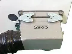
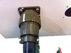
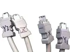
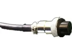
Imagen anterior
Siguiente imagen
(2) Inserte los conectores en sus posiciones correspondientes (cada posición es única). Inserte el conector del codificador en el servomotor adecuado según la numeración y el conector del amplificador en el ajustador de altura.
(3) Conecte el cable de alimentación del enfriador de agua dentro del armario de distribución en la posición designada, como se muestra en la figura:
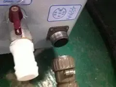
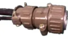
Imagen anterior
Siguiente imagen
(4) Encienda la alimentación principal. Se trata de un sistema trifásico de cuatro cables, donde el cable amarillo-verde es el de tierra y los tres restantes son los de fase. Con esto, se completa la conexión eléctrica del circuito externo. A continuación, veamos cómo conectar el enfriador de agua.
Precaución: Asegúrese de que el cable de tierra del cable de alimentación esté conectado a tierra de forma segura para evitar interferencias con las señales internas dentro del gabinete y minimizar el riesgo de fugas eléctricas.
Método de conexión del enfriador de agua
Requisitos de instalación
Asegúrese de que el dispensador de agua esté ubicado en un área estable, manteniendo una distancia adecuada de la pared. La ubicación de instalación del dispensador debe contar con suficiente espacio para la circulación del aire, a fin de evitar una refrigeración deficiente y temperaturas excesivas dentro del gabinete de distribución.
Inspección de equipos
Antes de la instalación, revise el tanque de agua limpia para asegurarse de que no haya residuos y que el agua esté libre de impurezas. Luego, inspeccione las juntas del sistema de tuberías para verificar que estén bien ajustadas y seguras.
Procedimiento de instalación
Siga las marcas en el exterior del dispensador de agua para conectar las tuberías de entrada y salida a los puertos de entrada y salida del láser. Asegúrese de que la dirección de los puertos de entrada y salida de las tuberías esté correctamente alineada. Antes de conectar las tuberías, verifique que no haya residuos ni objetos extraños en el exterior del dispensador.
Normas de calidad del agua
Compruebe y cierre la válvula de drenaje, luego llene el depósito de agua. El nivel del agua debe estar entre 30 mm y 50 mm por debajo de la altura del depósito para evitar desbordamientos. Está estrictamente prohibido usar agua del grifo para el enfriador de agua. Utilice agua purificada de alta calidad, agua destilada o agua desionizada. Está estrictamente prohibido añadir cualquier líquido corrosivo.
Depuración de arranque
Un interruptor neumático situado detrás del dispensador de agua controla la bomba. Tras conectar correctamente el circuito de agua, encienda la bomba para comprobar su funcionamiento. Una vez que la bomba arranque, revise todas las conexiones para detectar posibles fugas. Si encuentra alguna fuga, apague inmediatamente la bomba, repárela y, a continuación, intente reiniciarla y comprobar el sistema.
Ajuste de la temperatura del agua
En una habitación con aire acondicionado, la temperatura del agua suele ser de 22 a 24 grados Celsius. En habitaciones sin aire acondicionado, la temperatura del agua debe ser de 2 a 5 grados Celsius inferior a la temperatura ambiente. Si se observa condensación en las paredes de las tuberías, significa que la temperatura del dispensador de agua está configurada demasiado baja.
Ajuste láser de la boquilla y el puerto de la boquilla

Movimiento y ajuste de la boquilla
1) Boquilla
El diseño de la boquilla y las condiciones del flujo del chorro afectan directamente a la calidad del corte. La precisión de fabricación de la boquilla está estrechamente relacionada con la calidad del corte.
2) Funciones principales de la boquilla:
- Evite que la suciedad y otros objetos extraños entren en el cabezal de corte y dañen la lente de enfoque.
- The nozzle can modify the discharge of the cutting gas, controlling the size and area of gas diffusion and influencing the cutting quality.
The following image shows the situation when the nozzle is installed and not installed:

Steps to adjust the laser passing through the nozzle center
In contrast to CO2 laser cutting machines, fiber laser cutting machines do not rely on an optical path and only necessitate laser adjustment at the nozzle.
Apply ink (or transparent tape if not using ink) to the end of the nozzle and affix the white paper to it.
Adjust the laser output power between 30W and 50W, open the mechanical shutter, and quickly switch the electronic shutter once while observing the phenomenon.
Close the mechanical shutter, and remove the white paper, ensuring not to change its relative position.
If there is a significant difference between the nozzle position and the laser center, the paper will not align with the center hole. Since the laser center is fixed, adjust the nozzle center to match the laser center by rotating the adjustment screw on the cutting head handle.
Continue repeating the steps until the laser hole on the white paper aligns precisely with the center of the nozzle, confirming the proper alignment between the laser center and the nozzle center.
As shown in the following image:

The Influence of Nozzle on Cutting Quality and Selection of Nozzle Size
Relationship between Nozzle and Cutting Quality
When the center of the nozzle does not align with the laser center, it has the following impacts on cutting quality:
Cutting Section
Uneven gas distribution occurs when cutting gas is ejected, leading to a stepped appearance on one side of the cut section while the other side remains unaffected. This effect is minor when cutting materials below 3mm but becomes more significant for materials above 3mm, and in some cases, cutting may not be possible.
Sharp Angles
When cutting workpieces with sharp or small angles, localized over-melting can occur, making it challenging to cut thick plates.
Perforación
Piercing becomes unstable and challenging to control, leading to melting during the piercing of thick plates. The stability of piercing conditions is less critical for smaller workpieces.
In summary, the concentricity between the center of the nozzle and the laser is a crucial factor for cutting quality, particularly for thicker workpieces. Therefore, it is necessary to align the center of the nozzle with the laser to achieve better-cutting results.
Nota: Nozzle deformation or scaling can have the same impact on cutting quality as mentioned above. Therefore, the nozzle should be handled carefully to avoid deformation, and dirt should be cleaned promptly. The manufacturing precision of the nozzle requires high standards and must follow the correct installation methods. If poor nozzle quality results in changes in cutting conditions, the nozzle should be replaced promptly.
Selection of Nozzle Aperture
The differences in nozzle diameter are shown in the following table:
| Nozzle Aperture | Air Flow | Liquid Melt Removal Capacity |
| Pequeño | Rápido | Fuerte |
| Grande | Lento | Weak |
The nozzle diameter options include φ1.0mm, φ1.4mm, φ2.0mm, φ2.5mm, φ3.0mm, as shown in the diagram below:

Currently, the commonly used nozzle diameters are φ1.4mm and φ2.0mm, and their differences are as follows:
For thin sheets below 3mm
- Utilizing a nozzle with a diameter of 4mm will yield a reduced cutting area.
- Opting for a nozzle with a diameter of 2mm will result in a thicker cutting surface and an increased likelihood of molten residue accumulation at corners.
For thick plates above 3mm
- The higher the cutting power, the longer the heat dissipation and cutting time.
- Using a φ1.4mm nozzle may lead to a smaller gas diffusion area, which can cause instability during usage, although it is generally still usable.
- A φ2mm nozzle provides a larger gas diffusion area and slower gas flow, resulting in more stable cutting.
A 2.5mm diameter nozzle is suitable for cutting plates with a thickness greater than 10mm.
In summary, the nozzle size significantly impacts cutting and piercing quality. Laser cutting machines mostly use nozzle apertures of φ1.4mm and φ2mm.
Nota: The larger the nozzle aperture, the higher the possibility of sparks and molten splatters damaging the lens and shortening its lifespan.
Beam Focus Adjustment
The cutting quality is significantly influenced by the relationship between the beam focus and the material's surface during the laser cutting process. Correctly adjusting the focus position is crucial. This is usually accomplished by testing and adjusting the focus through cutting. The focus is positioned perfectly when the steel plate exhibits minimal slag and is the smallest size.
If there are changes in the relative position between the cutting head and the plate, the cutting head's and the sensor's zero points must be adjusted. Fine-tuning can be done by changing the cutting height in the software.
When significant adjustments are needed, the position of the sensor and its bracket may need to be adjusted to set the focus correctly.
Exercise caution when performing these adjustments, as mistakes could result in the cutting head hitting the surface and damaging the parts.
Relationship between Beam Focus Position and Cutting Effect
| Name and focus position | Cutting material and section properties |
| Zero focus: focus on the cut surface of the workpiece | Acero carbono Cutting Instructions |
| Focus on the surface of the cutting bow and arrow, the upper surface is smooth, and the lower surface is not smooth | |
| Positive focal length: focus is on the inner side of the cutting bow | Aluminio Cutting Instructions |
| The focus is in the center, so there is a larger smooth surface, the cutting width is wider than the zero focus, the airflow is larger when cutting, and the perforation time is longer than the zero focus | |
| Negative Focus: The focus is lower than the cutting bow | Acero inoxidable Cutting Instructions |
| Stainless steel high-pressure nitrogen cutting, blowing away the slag to protect the cutting section, the cutting width increases with the thickness of the workpiece |
Choosing the Cutting Speed
Choosing the appropriate cutting speed is vital for laser cutting machines and is determined by the material and thickness of the workpiece. The cutting speed plays a crucial role in determining the quality of laser cutting.
Choosing the appropriate cutting speed improves the efficiency of the laser cutting machine and ensures high-quality cutting.
The following are the effects of different cutting speeds on the cutting quality:
Effects of Excessive Cutting Speed on Cutting Quality
- It may result in non-cutting and splattering sparks.
- Some areas may be cut while others may not.
- It leads to an overall increase in the thickness of the cutting section without fusion.
- The excessive cutting speed causes the material to be insufficiently cut, resulting in an inclined cutting section with melted residues at the bottom. Refer to the diagram:

Effects of Insufficient Cutting Speed on Cutting Quality
- It leads to excessive melting and rough cutting sections.
- The width of the kerf increases, causing the entire area to melt into smaller rounded or sharp corners, resulting in poor cutting quality.
- The cutting efficiency could be higher, affecting productivity.
- Observe the cutting sparks to determine the appropriate cutting feed speed: if they spread from top to bottom and slope, the cutting speed is too fast. If the sparks condense without diffusing, the cutting speed is too slow. With the correct cutting speed, the cutting surface will have smoother lines, and the lower part of the material will not fuse. Refer to the diagram:

Selection Guide for Laser Cutting Gas and Pressure
The cutting gas chosen for laser cutting depends on the material being cut, and it plays a crucial role in determining the cutting quality. The selection of cutting gas and the appropriate pressure significantly impact the overall cutting performance and the resulting quality of the cut.
The main functions of cutting gas are to assist combustion and heat dissipation, blow away residues, and prevent them from damaging the focusing mirror in the nozzle.
Influence of Cutting Gas and Pressure on Cutting Quality
- Proper cutting gas helps in combustion and heat dissipation, improving cutting quality.
- Insufficient cutting gas pressure affects the cutting process due to residue accumulation, and the cutting speed may not meet production requirements.
- High cutting gas pressure leads to rough cutting surfaces, wider kerfs, and diminished cutting quality.
Impact of Cutting Gas Pressure on Perforation
- If the pressure is too low, the laser will have difficulty penetrating the cutting plate, leading to prolonged drilling time and reduced productivity.
- Excessive gas pressure causes the melting point to melt and form more prominent molten spots, affecting cutting quality.
- Higher pressure is generally used for sheet metal for laser punching, while lower pressure is suitable for punching thick plates.
- When cutting ordinary carbon steel, the thicker the material, the lower the cutting gas pressure.
- High cutting gas pressure is required when cutting stainless steel, regardless of material thickness.
In summary, the selection of laser-cutting gas and pressure must be adjusted based on specific conditions and requirements for each application.
Most laser-cutting devices are equipped with two gas pipelines: one for oxygen and air and the other for high-pressure nitrogen. Both gas channels are connected to pressure-reducing valves, as shown in the diagram:

Explanation of Pressure Reducing Valves in the diagram: The left gauge indicates the current pressure, while the correct gauge displays the remaining gas capacity.
Advertencia:
- The nitrogen supply pressure should not exceed 20 Kg.
- The oxygen supply pressure should not exceed 10 Kg to prevent the bursting of the gas pipeline.
The Impact of Laser Cutting Machine Power on Cutting Quality
The cutting quality of a laser cutting machine is influenced by its power. It is crucial to select the appropriate cutting power according to the material and thickness of the workpiece. More than sufficient laser power can lead to poor cutting outcomes.
- Insufficient laser power may lead to the inability to cut through the material.
- Setting the laser power too high can cause excessive melting of the cutting surface, wider kerfs, and inferior cutting quality.
- Insufficient laser power can result in cutting residues and scars on the cutting section.
Therefore, setting the appropriate laser power and suitable cutting gas and pressure will yield excellent cutting quality without forming melt spots.
Maintenance and Troubleshooting of Fiber Laser Cutting Machine
Regular maintenance is required to ensure the laser cutting machine's proper operation. Due to the machine's use of high-precision components, handling them carefully and strictly following the operating procedures during maintenance is crucial. It is also recommended to designate a dedicated person for care to prevent damage to the components.
It is recommended that users keep the following spare parts readily available:
- Acetone (purity of 99.5%, water content below 0.3%, 500ml capacity)
- Degreasing cotton (5 packs, medical-grade or optical-grade)
- Alcohol (500ml, with a purity of 99.5% or higher)
- Dropper (medical-grade)
- Cotton swabs (two packs)
- Multimeter (one)
Installation or Replacement Steps for Cutting Head Internal Lens

(1) Before installing the optical lens, it is essential to wear clean clothing, wash hands with soap or more sanitary, and put on sterile white gloves. Do not touch any part of the lens with bare hands, and handle the lens from the side without directly touching the coated surface.
(2) When assembling the lens, avoid blowing on it with your mouth. Place the lens on a clean tabletop and a few sheets of professional paper underneath.
To ensure proper care of the lens and prevent damage, it is advised to handle it cautiously, avoiding any scratches or accidental drops. To ensure the lens remains in optimal condition, it is essential to exercise caution when taking it to prevent scratches or accidental drops. Avoid exerting pressure on the coated surface of the lens. Before installing the lens, it is advisable to thoroughly clean the lens holder with a clean air gun to eliminate any dust or debris. Subsequently, gently place the lens into the lens holder.
(3) When installing the lens onto the lens holder, avoid applying excessive force when securing the lens, as it may cause deformation and affect the quality of the beam.
(4) Precautions when replacing the optical lens:
- Handle the lens carefully when removing it from the packaging to avoid scratching it.
- Before removing the packaging paper, avoid exerting any pressure on the lens.
- Wear clean gloves when removing the protective and focusing lenses from the packaging, and handle them from the side.
- Avoid dust or other debris falling on the lens when removing the packaging paper.
- Use a clean air gun to blow off dust from the lens, and then place it on an optical lens paper.
- Clean the lens holder and bracket to remove dust and dirt, to prevent foreign objects from falling on the lens during assembly.
- Do not apply excessive force when installing the lens onto the holder to avoid deformation.
- After lens assembly, use a clean air gun to remove dust or foreign objects from the lens.
Cleaning Procedure for Laser Cutting Machine Lens
First, use a clean air gun to blow off the dust from the lens.
Próximo, employ a clean cotton swab to eliminate any dirt or debris. Dip the cotton swab into fresh, high-quality alcohol or acetone and gently glide it in circular motions, commencing from the center of the lens and gradually progressing toward the outer edges.
Continue performing this procedure until the lens is immaculate, ensuring that you replace the cotton swab with a fresh, clean one after each iteration. Employ a clean cloth to remove any residual traces from the lens, avoiding scratching. Inspect the lens under adequate lighting conditions to assess its reflection quality. A good reflection indicates that the lens is clean. If the review is unsatisfactory, proceed with the cleaning process.
Finally, use the same method to place the cleaned lens into the holder. Do not use the same cotton swab for cleaning again.
Storage of Optical Lenses
- Proper storage of optical lenses is crucial for maintaining their quality.
- It is essential to store the lenses within a temperature range of 10-30°C (50-86°F). Avoid placing the lenses in a freezer or any other environment that can lead to condensation, damaging the lenses.
- The storage environment temperature should not exceed 30°C to avoid affecting the lens surface coating.
- When storing the lenses in a box, they should be placed in a vibration-free environment to prevent lens deformation and maintain performance.
Electrical Inspection
Maintenance primarily involves:
- I was checking the stability of the daily power supply voltage.
- We are keeping the machine's electrical cabinet clean and adequately ventilated.
- We are ensuring the integrity and safety of each electrical component.
Maintenance Cycle
- The maintenance cycles for the laser, water chiller, and air compressor should follow the timetable specified in the user manual.
- The machine should undergo its initial maintenance after 24 hours of operation, followed by a subsequent maintenance session after 100 hours. A comprehensive overhaul should be conducted after six months. After that, regular maintenance should be scheduled every six months or annually, tailored to each customer's specific circumstances and requirements.
Maintenance During Operation
Before operating the machine, it is essential to perform routine checks and maintenance on the laser-cutting device based on the daily inspection checklist. Stop immediately and conduct a thorough inspection if you notice any abnormal sounds during the machine's operation. After using the laser cutting machine, shut it down in the correct sequence and clean the machine table and its surrounding area. Do not leave any unrelated items on the machine table or control panel.
- Regularly check the lubrication pump oil level and refill as necessary to ensure sufficient lubrication of the X-axis and Y-axis rails, maintaining machine accuracy and extending the lifespan of the X-axis and Y-axis rails.
- Clean the Z-axis linear guide and lead screw weekly, removing dust and applying machine oil.
- Check the water and air pipes weekly for any damage and promptly notify company personnel for repairs if any damage is found.
- Clean the air weekly to filter out debris and dust.
- Check the internal cooling water level of the water chiller weekly and refill it if necessary.
- Inspect the contamination of the focusing lens every two weeks and clean it if required to ensure its lifespan.
- Daily inspection of the protective lens to maintain cutting effectiveness.
- Monthly review of the air path to eliminate any potential hazards.
- Regularly check for external cable damage and loose connections in the distribution cabinet wiring interface.
- Adjust the machine's level after six months to ensure cutting precision.
Maintenance During Idle Periods
When the machine is not used for an extended period, apply a protective coating such as machine oil or grease to the moving parts. Wrap them with rust-proof paper and regularly check for rust, removing it promptly and applying rust prevention measures where necessary. (Consider adding a dust cover if the budget allows.) Regularly clean and inspect the machine.
Appendix: Common Troubleshooting Methods
| Problema | Causa | Solución |
| Parts processing without auxiliary gas output | Lack of pressure | Check air pressure |
| Solenoid or wire is broken | Check the solenoid valve or solenoid valve circuit | |
| There is abnormal noise in the shaft movement | No lubricant on moving parts | Add lubricant |
| Check if the motion path is safe | Check that moving parts paths are safe | |
| The cutting head has no laser or the light is weak | No light signal | Check the PWM signal line |
| Laser or fiber is broken | Check if the laser is alarming | |
| Nozzle block, optical path part | Replace the nozzle, adjust the optical path | |
| Crop pattern does not match paper size | Program error | Read the instructions and check for correct operation |
| Positioning accuracy suffers | Check whether the machine accuracy is qualified | |
| Damaged steering gear | Replace or Repair Servos |
The world's top fiber laser cutting machine manufacturers
The leading manufacturers of laser cutting machines worldwide include:
- Alemania: Trumpf
- Italia: Prima
- Suiza: Bystronic
- Japón: Amada, Mazak, NTC
- Australia: HGLaserLab
- Porcelana: KRRASS
Nota: No "best" choice exists, only a "better" option. Choose what suits you best. Laser cutting is a mature manufacturing process, and the performance of top-tier laser cutting machines is comparable. The selection of a high-quality laser cutting machine mainly depends on the production materials. The following factors need to be considered:
- Cutting width: Typical laser cutting widths range from 0.10mm to 0.20mm.
- Smooth cutting surface: The cut surface should be free of burrs.
- Low thermal deformation: Laser cutting is characterized by thin cuts, high speeds, and concentrated energy, which minimizes heat transfer and reduces deformation.
- Suitable for processing large products: Laser processing does not require molds for manufacturing large products, resulting in lower production costs and improved product quality.
- Laser processing is highly advantageous for new product development as it allows for immediate implementation after the completion of product design, significantly reducing development cycles.
- Material savings: Laser processing utilizes computer programming to cut products into different shapes, maximizing material utilization.
Remember to consider these factors when choosing a laser-cutting machine.
Operation of fiber laser cutting machine
To ensure both machine performance and personal safety, it is crucial to have a comprehensive understanding of the components and operating procedures of a laser cutting machine before utilizing it. Before commencing its use, conduct the following checks:
- Inspect the oil level of the device and, if required, replenish it to keep it within the designated normal range.
- Check for any leaks in the water and air circuits to ensure proper air and water quality without contamination.
- To verify the coaxial alignment of the laser and nozzle, ensure that the laser beam is emitted precisely from the center of the gas nozzle.
- Ensure that the nozzle of the cutting gas is suitable for the cutting process and replace it if necessary.
- Check the connection of the cutting assist gas and adjust the gas pressure to an appropriate level if needed.
Safety precautions and safety signs before and during use
Common signs on fiber laser cutting machines include:

Sign indicating "Caution": Failure to follow proper procedures may result in personal injury or equipment damage.

Sign indicating the presence of a laser beam: Do not pass through the shaft, as it can cause burns or life-threatening injuries.

Sign representing high-voltage power danger: Keep away from high voltage to avoid electric shock or life-threatening situations.
It is essential to be aware of and adhere to these safety precautions and signs when operating a fiber laser cutting machine.
Precautions when using a laser cutting machine
- Avoid direct eye contact with the laser, including the red light.
- Ensure you and any non-work items are positioned away from the laser beam path when the shutter is open.
- Operators must wear protective goggles and stay present during the entire operation of the laser cutting machine.
- If any problems arise during operation, it is crucial to immediately press the emergency stop switch or shut off the main power.
- Regularly monitor the cooling water temperature and working gas pressure while the machine operates.
- Only operate the machine if properly trained and following safety procedures. Unauthorized personnel are strictly prohibited from using the device.
- The laser cutting machine's laser is a Class 4 laser product. The invisible laser beam, lens reflection, and scattered light can harm the human body, especially the eyes. Personnel must take necessary precautions to prevent fire accidents.
- The waste gas generated during laser cutting can injure the operator. Therefore, ensure that the machine's dust extraction function is functioning correctly.
- Keep the laser cutting equipment clean and orderly, lubricate as instructed, and manage tools and accessories properly to avoid loss. If malfunctions occur and the operator cannot resolve the issue, immediately stop the machine and inform the relevant engineers.
- To prevent electric shock damage, only allow professional technicians to inspect or repair the electrical control part of the laser cutting machine.
Sequence for turning on/off a fiber laser cutting machine
The sequence of turning on the machine:
- First, power the control cabinet from the external power supply.
- Ensure the water chiller switch is in the on position (do not turn off the water chiller switch after use).
- Check if the emergency stop switch is in the released position.
- Rotate the key switch to the "on" position.
- Power on the computer.
- Finally, switch on the laser power on the left side.
To turn off the laser cutting machine, reverse the order of these steps.
Software usage and programming
To obtain detailed instructions on utilizing the software, please consult the accompanying manual accompanying the device. The manual contains comprehensive information regarding the specific details that pertain to the software's usage and functionality. You will thoroughly understand how to operate the software effectively by referring to the manual.
Automatic calibration of the height sensor
If the height sensor needs to be calibrated when replacing the nozzle or if the distance of the servo is inaccurate, calibration can correct the height of the follow-up component. Follow these steps:
- Move the cutting head downward to approximately 5mm above the sheet's surface.
- Select "Calibration" → "Floating Head Calibration" → "Confirm" on the height adjustment torch.
- During the process, the cutting head will descend twice, taking about 10 seconds. Check the position of the sheet during this time.
- After calibration, the calibration curve will be displayed on the height adjustment torch. For a typical calibration result, the angle should be smooth. If the calibration result is unsatisfactory, it will affect the cutting effect, and recalibration is required.
Several factors may affect the calibration result, including:
- The unstable surface of the sheet.
- The vibration of the Z-axis slider.
- Severe external electrical interference.
The calibration result is divided into A, B, C, and D categories. The laser cutting machine can be used generally if the calibration result is at "C" or above. If the result is "D," recalibration is necessary to eliminate interference.
Safety of laser cutting machines
Every laser-cutting machine operator must know and adhere to safety measures to ensure their safety.
Safety measures for laser cutting machines
- Appoint a safety administrator to determine their responsibilities and provide training to laser processing operators.
- Define laser safety management areas and post warning signs at the entrances. The symptoms should include information about machine power, laser type, prohibition of unauthorized entry, and the importance of eye protection. They should also include the name of the safety manager.
- Laser processing machine operators must undergo specialized training and can only operate the machine with permission from the safety administrator.
- When the laser processing machine is unused, the key switch must be unplugged and locked to prevent accidental operation and injury.
- Ensure that smoke, dust, and laser working gases generated during manufacturing are exhausted outdoors through an exhaust pipe. The required gas cylinders for machine operation should be stored in an organized and secure manner.
The knowledge that was laser-cutting machine operators should be aware of
- Laser-cutting machine operators must undergo specialized training and reach a certain level of proficiency before operating the machine with the approval of the safety administrator.
- Operators or personnel should wear appropriate laser safety goggles and protective clothing when using or near a laser. Adequate indoor lighting should be provided where protective goggles are required to ensure smooth operation.
- Providing a designated processing area or protective screen is essential to safeguard operators. Additionally, safety devices must be implemented to prevent the scattering of laser beams and ensure the well-being of the operators.
- When opening the processing room door, the laser shutter should be closed.
Safety precautions for laser cutting machines
Laser radiation poses primary risks to the eyes and skin. Laser exposure can cause burns on any part of the body. Therefore, it is essential to avoid placing any part of the body in the laser beam path to prevent accidental injuries.
Protecting the eyes and skin
During laser processing, commonly used lasers include CO2 and YAG lasers, each with different levels of harm to the human body. YAG lasers pose more significant hazards as their wavelength has high transmittance through the human eye, potentially damaging the retina. On the other hand, CO2 lasers primarily cause corneal burns to the eyes. Both types of laser exposure carry risks of cataracts and skin burns. Hence, it is crucial to take appropriate protective measures based on the type of laser being used during the adjustment process.
Fire safety precautions
Laser cutting often involves using oxygen and sparks during the cutting process, increasing the risk of fire. Therefore, the work area should be free of flammable and combustible materials, and necessary protective measures should be in place.
Electrical safety
To minimize the risk of electric shock, you should refrain from touching switches while your hands are wet.
Moreover, operators need to exercise caution around areas of the laser cutting machine designated by illumination signs, as they indicate the presence of high voltage or electrical components. This caution should be extended when approaching these components or performing maintenance tasks. Examples of such areas include protective covers for servo motor locations, junction boxes positioned behind columns, transformer cabinets of the laser-cutting machine, and the doors of electrical cabinets.
Familiarity with functions and buttons
It is essential to thoroughly read the machine manual and electrical schematics to become familiar with the functions and buttons of the laser cutting machine.
Prohibition of unauthorized changes to machine parameters
Do not easily open electrical doors and prohibit unauthorized changes to machine parameters, servo parameters, and potentiometers (matching with the calibration table). If changes are necessary, they must be done after receiving training from the laser cutting equipment manufacturer and obtaining approval from a professional. Remember to record parameter values before making any changes to facilitate restoration to the original state if needed.
Protection against high voltage and X-ray hazards
Laser cutting machines operate at power voltages ranging from several thousand to tens of thousands of volts, so it is essential to prevent exposure to high voltage and X-rays generated by electron tubes under high voltage.
Avoid contact with energized components in electrical cabinets
When the electrical cabinet is energized, do not touch energized components such as CNC devices, servo devices, transformers, fans, etc.
Advertencia: Wait 5 minutes before touching the terminals after a power outage. After the power is cut off, high voltage may be between the power line terminals. To avoid electric shock, do not touch them immediately.
Fiber Laser Cutting Thickness and Speed Chart
Here is a chart of laser-cutting thicknesses that may be helpful to you:

If you need to choose a Fiber Laser Cutting Machine suitable for you, enter our Máquina de corte láser de fibra página


