Press brake tooling is the direct interface between the press brake and the sheet metal part. A press brake may have a rigid frame, a precise CNC controller, a stable hydraulic or servo drive system, and an accurate backgauge, but the final bend quality still depends on the punch and die that touch the workpiece. The right punch and die can reduce trial bending, protect material surfaces, improve angle consistency, and make production more predictable. The wrong tooling can create cracked bends, excessive marking, angle variation, long setup time, damaged tools, or even unsafe overload conditions.
For buyers, engineers, and production managers, press brake tooling should not be treated as a small accessory purchased after the machine. It is part of the bending system. When a factory plans a new листогибочный пресс, the tooling plan should be discussed together with machine tonnage, bending length, controller capability, crowning, clamping, backgauge travel, material type, and production mix. This is especially important for manufacturers that handle different materials, short batches, cabinets, enclosures, brackets, panels, frames, HVAC components, electrical boxes, and custom sheet metal parts.
This guide explains how to choose the right punch and die in a practical, business-oriented way. It combines core bending principles, industry rules of thumb, safety considerations, and procurement logic. The goal is not to make tooling selection look complicated. The goal is to help you ask the right questions before purchase, so that your press brake tooling supports real production instead of becoming a hidden bottleneck.
Оглавление
What press brake tooling means in real production

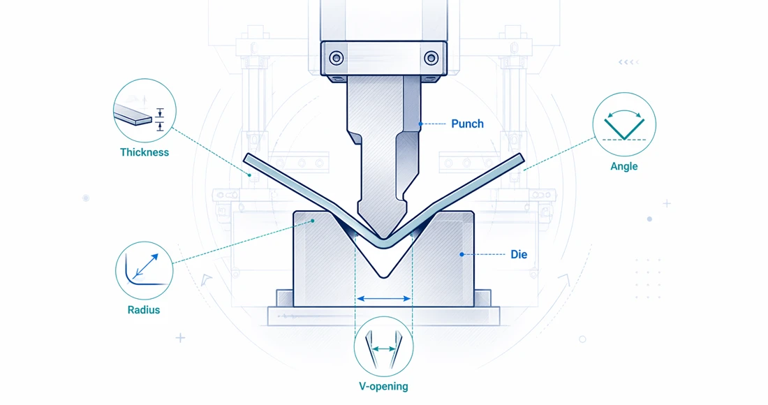
Press brake tooling normally refers to the upper punch and lower die used to bend sheet metal on a press brake. The punch descends into the die opening and forces the material to deform. Depending on the setup, the bend may be produced by air bending, bottoming, or coining. In modern production, air bending is very common because it offers flexibility across angles and materials when the punch, die opening, CNC depth control, and bend allowance are managed correctly.
KRRASS explains in its press brake tooling chart guide that tooling selection is linked to material type, thickness, bend angle, machine compatibility, and the desired forming result. That is the right way to think about tooling. A punch and die are not selected only by appearance. They are selected because they support a specific bend geometry, inside radius, flange length, tonnage requirement, material behavior, and production method.
In a factory environment, tooling affects several cost centers at the same time. It affects setup time because operators must install, align, clamp, and segment tools. It affects scrap because incorrect tooling changes angle, radius, and flat pattern results. It affects machine utilization because unsuitable tools may require repeated test bends. It affects safety because tool load limits and press brake tonnage must be respected. It also affects quote accuracy because bend feasibility, tool availability, and setup complexity influence production cost.
Core tooling elements
| Tooling element | What it does | Why it matters commercially |
|---|---|---|
| Upper punch | Pushes the sheet into the die and defines clearance around the bend | Determines reach, bending shape, inside access, and risk of collision |
| Lower die | Supports the sheet and provides the V opening or forming cavity | Strongly affects inside radius, required tonnage, minimum flange, and surface marking |
| Tool holder or clamping | Secures the punch and die to the press brake | Affects setup speed, alignment, operator workload, and repeatability |
| Segmented tooling | Allows short tool sections to be combined for different part lengths | Helps produce boxes, pans, return flanges, and short-batch parts |
| Crowning and tool alignment | Compensates for deflection across the bending length | Helps maintain angle consistency from left to right |
This table is simple, but it explains why tooling is a production investment rather than only a consumable purchase. A low-price tool set that slows every setup or marks every cosmetic part can cost more than a well-selected tooling package.
Punch and die selection starts with the part, not the catalog
A common mistake is to open a tooling catalog first and choose a punch or die that looks standard. The better method is to start from the part drawing. The drawing tells you the material, thickness, bend angle, inside radius, flange dimensions, part length, hole positions, return flanges, and cosmetic requirements. Tooling selection is then a process of matching these requirements to the available machine and forming method.
Before choosing press brake tooling, gather the following information:
| Required information | Why it matters |
|---|---|
| Material grade | Mild steel, stainless steel, aluminum, high-strength steel, and coated sheet bend differently |
| Толщина материала | Thickness controls die opening, tonnage, radius, and flange limit |
| Длина изгиба | Longer bends require more total force and more attention to deflection |
| Required angle | Acute, 90-degree, and obtuse bends may need different punch angles |
| Inside radius | Must be compatible with material ductility, die opening, and punch radius |
| Minimum flange | Determines whether the part can sit safely over the selected V opening |
| Part shape | Boxes, channels, and return flanges may require gooseneck punches or segmented tools |
| Surface requirement | Visible panels may require larger radii, clean dies, protective film, or anti-marking tooling |
| Quantity and repeatability | High-volume work may justify dedicated tooling or faster clamping systems |
This approach is especially important when purchasing a machine and tooling package together. For example, if a customer plans to bend long stainless steel panels, the tooling plan should address tonnage, surface protection, and crowning from the beginning. If a customer mainly produces electrical cabinets, the tooling plan should include segmented punches, gooseneck punches, and dies suitable for typical enclosure flanges. If a customer produces heavy brackets, tool load capacity and die width become more important than cosmetic surface protection.
Choose the bending method before choosing the tool profile
The same sheet metal part can often be bent by different forming methods, but each method changes tool selection. The three most discussed methods are air bending, bottoming, and coining. Air bending is common in CNC press brake production because one punch and die combination can produce multiple angles by changing ram depth. Bottoming and coining use more force and more tool contact, but they may be selected for specific accuracy or forming requirements.
Он KRRASS press brake basics guide describes press brake operation, bending processes, components, and safety as connected topics. That connection matters. Tooling selection is not separate from the bending method. If the method changes, the punch angle, die angle, die opening, forming pressure, and expected springback can all change.
| Bending method | Typical tooling logic | Main advantages | Main limitations |
|---|---|---|---|
| Управление воздухом | Sheet contacts punch tip and two die shoulders; bend angle is controlled by ram depth | Flexible, lower tonnage, good for varied angles and materials | More sensitive to material variation and springback |
| Дно | Material is pressed closer to the die angle with more contact | Better angle stability than air bending in some cases | Requires more tonnage and more specific tooling |
| Монетизация | Material is compressed heavily into the die to reduce springback | High angle control for specific applications | Very high tonnage, high tool stress, less flexible |
For most modern general-purpose fabrication, air bending is the practical starting point. It allows one setup to cover different angles when the CNC controller, punch, die, and material data are well managed. However, air bending requires disciplined tool selection. A poor V opening choice can create an oversized inside radius, excessive springback, unstable flanges, or high tonnage. A punch tip that is too sharp can concentrate stress and increase cracking risk, especially on hard or less ductile material.
V-die opening: the most important die selection decision

The V-die opening is one of the most important choices in press brake tooling. It affects the inside radius, required tonnage, minimum flange length, angle stability, and marking level. Many fabricators use a general starting rule: select a V opening around 6 to 8 times the material thickness for air bending mild steel. WILA also describes 6 to 8 times sheet thickness as a common rule of thumb for air bending steel, while noting that changing the V opening influences radius, required force, marking, and minimum leg length.
The widely used “rule of eight” is useful because it gives buyers and operators a quick starting point. However, it should not be treated as a universal law. Thin material, thick plate, stainless steel, aluminum, high-strength steel, cosmetic sheet, and very short flanges may require adjustment. The practical rule is simple: use the 6x to 8x range as a first estimate, then check the required radius, minimum flange, tonnage, and material behavior.
Typical V-opening starting points for air bending
| Толщина материала | Common V opening at 6x | Common V opening at 8x | Practical note |
|---|---|---|---|
| 1.0 mm | 6 мм | 8 мм | Small V openings need careful tool alignment and clean material support |
| 1,5 мм | 9 mm | 12 мм | Often used for cabinets, light enclosures, covers, and panels |
| 2,0 мм | 12 мм | 16 мм | Common range for general sheet metal fabrication |
| 3,0 мм | 18 mm | 24 мм | Check flange length and tonnage before production |
| 4,0 мм | 24 мм | 32 мм | Larger radius and higher force become more visible in the part result |
| 6,0 мм | 36 mm | 48 мм | Machine capacity and tooling load rating must be verified |
| 8,0 мм | 48 мм | 64 мм | Heavy bending needs serious tonnage and deflection planning |
| 10.0 mm | 60 mm | 80 мм | Confirm material grade, bend length, and machine limits before quoting |
These numbers are not a substitute for a tooling chart or bending calculation. They are a planning table for early discussion. For a real job, the final die selection should be confirmed against the part drawing, machine tonnage, tooling load rating, material grade, and whether the customer accepts the resulting inside radius.
How V opening changes radius, tonnage, and flange length
A wider V opening generally creates a larger inside radius, reduces required tonnage, and requires a longer minimum flange. A narrower V opening generally creates a smaller inside radius, increases tonnage, and allows a shorter flange. This trade-off is central to press brake tooling selection.
For example, a 3 mm mild steel part might be air bent on a V24 die as a normal starting point. If the drawing requires a smaller flange or tighter inside radius, the operator may consider V18. That narrower die may help the geometry, but it increases bending force and may increase tool marking. If the part has a visible surface, a narrower die may be unacceptable unless protective methods are used. If the part is stainless steel, the increased force and springback must also be considered.
| Die-opening choice | Effect on inside radius | Effect on tonnage | Effect on minimum flange | Effect on marking risk |
|---|---|---|---|---|
| Narrower V opening | Smaller radius | Higher force | Shorter flange possible | Higher marking risk |
| Standard V opening | Balanced radius | Balanced force | Normal flange requirement | Normal marking risk |
| Wider V opening | Larger radius | Lower force | Longer flange needed | Lower marking risk |
This table is useful for sales and engineering discussions because it shows why there is no single “best” die. The best die is the one that balances the drawing requirement, material, available press brake capacity, and production goal.
Tonnage calculation: why tooling selection must respect force limits
Press brake tooling must be selected with tonnage in mind. If the die opening is too small, the required bending force rises quickly. If the bend length is long, the total force rises again. If the material is stronger than standard mild steel, the required force rises again. This is why tonnage calculation is not only a machine-sizing issue. It is a tooling-selection issue.
A common simplified air-bending formula for mild steel is:
Tonnage per meter ≈ 1.42 × tensile strength factor × material thickness² / V opening
In many practical shop charts, the principle is more important than the exact formula version: thicker material, longer bends, stronger material, and smaller V openings increase required force. The KRRASS tooling page also shows that tooling has maximum tonnage ratings. Those ratings must be respected. A press brake may have enough nominal machine capacity, but the selected tool may not be rated for the load.
Example tonnage comparison for mild steel air bending
The table below uses a simplified proportional comparison. It is designed for planning discussion, not final certification. Always confirm with the machine manual, tooling supplier data, and a reliable bending force calculator before production.
| Толщина материала | Длина изгиба | V-образное отверстие | Relative force trend | Practical interpretation |
|---|---|---|---|---|
| 2 мм | 1 m | 16 мм | Baseline | Normal light-gauge bending setup |
| 2 мм | 1 m | 12 мм | Выше | Smaller radius and flange may cost more force |
| 3 мм | 1 m | 24 мм | About 2.25x thickness effect before V adjustment | Thickness has a strong force effect |
| 3 мм | 2 m | 24 мм | About 2x the 1 m force | Bend length multiplies total tonnage |
| 4 мм | 1 m | 32 мм | Much higher than 2 mm | Confirm machine capacity and tool rating |
| 6 мм | 1 m | 48 мм | Heavy bending range | Requires careful tonnage, deflection, and safety planning |
For KRRASS customers, this is where a калькулятор изгибающей силы or machine-specific calculation support becomes valuable. The buying question should not only be “Can the machine bend this thickness?” A better question is: “Can this machine, this tooling, this die opening, and this bend length safely and repeatedly produce this part?”
Material behavior: mild steel, stainless steel, aluminum, and high-strength sheet

Different metals behave differently under bending. Mild steel is often used as the baseline because it is common and relatively predictable. Stainless steel normally requires more force and may show more springback. Aluminum is often more sensitive to cracking across certain tempers and grain directions. High-strength steel requires careful radius and tonnage review because it can exceed assumptions based on ordinary mild steel.
Official material testing standards show why mechanical properties matter. ISO 6892-1:2019 covers tensile testing of metallic materials at room temperature, while ISO 7438 specifies a bend test method for metallic materials. These standards are not tooling catalogs, but they explain the engineering basis: bending performance depends on material properties, ductility, and deformation behavior.
Practical material factors for tooling selection
| Группа материалов | Tooling concern | Practical recommendation |
|---|---|---|
| Низкоуглеродистая сталь | Usually predictable, but grade and thickness still matter | Start with standard V-opening rules, then confirm radius and tonnage |
| Нержавеющая сталь | Higher springback and higher force than mild steel | Use suitable die opening, consider larger radius, and verify tonnage margin |
| Алюминий | Some tempers crack more easily; surface marking may be visible | Avoid overly sharp punch tips and confirm grain direction where needed |
| Galvanized or pre-painted sheet | Surface damage can create quality complaints | Use clean dies, protective film, larger shoulders, or anti-marking solutions |
| Высокопрочная сталь | Higher yield strength and springback | Increase radius where required and avoid assuming mild-steel tooling rules |
A practical tooling conversation should include the exact material grade, not only the word “steel” or “aluminum.” For instance, 304 stainless steel and low-carbon mild steel may both be 2 mm thick, but they do not bend the same way. Aluminum 5052-H32 and 6061-T6 also behave differently. For parts with critical bends, sample testing is often more reliable than guessing from a generic category.
Punch selection: angle, tip radius, height, and shape
The punch is the upper tool that contacts the inside of the bend. Punch selection affects clearance, inside radius, bend angle, and collision risk. For simple open bends, a standard straight punch may work well. For deeper boxes, return flanges, channels, and cabinet components, a gooseneck punch may be required to avoid part collision. For acute bends, an acute punch may be needed. For soft or cosmetic materials, a larger punch nose radius may reduce cracking or marking risk.
Main punch types and use cases
| Punch type | Common use | Selection concern |
|---|---|---|
| Straight punch | General 90-degree bends and simple profiles | Check height, angle, and tip radius |
| Acute punch | Acute angles and pre-bending operations | Confirm die compatibility and tool strength |
| Gooseneck punch | Boxes, pans, return flanges, and deep profiles | Check throat clearance and load rating |
| Radius punch | Large-radius bends | Confirm target radius and springback behavior |
| Hemming punch | Flattening or hemming operations | Usually requires staged forming and proper dies |
| Segmented punch set | Short sections combined for part length and box work | Improves flexibility but requires organized setup management |
The punch angle must support the target bend. For air bending a 90-degree final angle, a punch angle smaller than 90 degrees is often used to allow overbending and springback compensation. For example, an 88-degree punch may support common air-bending work. Acute punches are used where the final part angle or process requires deeper overbending. However, sharp punches are not automatically better. A punch nose that is too sharp relative to material thickness and ductility can create high stress concentration.
Punch nose radius and cracking risk
The punch nose radius should be chosen with the material and required inside radius in mind. If the punch nose is too small for the material, the bend may crack, especially on hard aluminum, high-strength steel, or parts bent against the grain. If the punch nose is too large, the part may not achieve the required inside geometry or may need a different flat pattern.
A practical rule is to avoid forcing a radius smaller than the material can tolerate. The drawing may call for a tight radius, but the material may not support it without cracking. In such cases, the correct business response is not to force the bend. The correct response is to review the design, material, bend direction, and radius requirement with the customer before production.
Die selection: V dies, multi-V dies, acute dies, hemming dies, and adjustable dies
The die is the lower tool that supports the sheet. In air bending, the V die is the most common die type. It may be a single-V die, multi-V die, or adjustable die. The correct die depends on thickness range, production volume, part length, surface requirements, and bending force.
The KRRASS инструменты для листогибочного пресса page shows examples such as multi-V dies and adjustable dies. Multi-V dies can be convenient for factories that process a range of thicknesses because one die body may offer multiple openings. Adjustable dies are useful for larger V openings or changing material thickness without replacing the entire die. However, convenience must be balanced against precision, tool height, rigidity, and the bending task.
Die types and purchasing logic
| Die type | Best fit | Commercial advantage | Caution |
|---|---|---|---|
| Single-V die | Repeated production with known thickness | Stable setup and clear process control | Less flexible across thickness ranges |
| Multi-V die | General fabrication with varied material | Flexible and economical for mixed jobs | Requires careful orientation and handling |
| Acute die | Acute bends and staged forming | Enables special angle work | More specific use case |
| Hemming die | Closed hems and flattened edges | Supports safe edges and product stiffness | Usually needs staged forming |
| Adjustable die | Thick plate or varied large openings | Reduces need for many large dies | Must confirm rigidity and load capacity |
| Urethane or anti-marking die support | Cosmetic or soft materials | Reduces marking | May affect angle behavior and tool life |
For a factory producing a wide variety of custom sheet metal parts, a combination of standard V dies, segmented tooling, a gooseneck punch set, and selected special dies often provides a practical starting package. For a factory producing one high-volume part family, dedicated tools may produce better speed, consistency, and cost per part.
Minimum flange length: the often-forgotten constraint

Minimum flange length is one of the most common reasons a selected die fails in real production. In air bending, the sheet must sit safely across the die shoulders. If the flange is too short for the V opening, the material may fall into the die, become unstable, or produce an inaccurate bend. This is why a wider die opening is not always better, even though it reduces tonnage and marking.
A simplified planning rule is that minimum flange length is often around 70% of the V opening, depending on tooling geometry and process conditions. This is only a starting estimate. The actual value depends on die shoulder radius, material thickness, bend angle, punch geometry, and machine setup.
Minimum flange planning table
| V-образное отверстие | Approximate planning flange at 70% of V | Typical concern |
|---|---|---|
| 8 мм | 5.6 mm | Very small parts require careful handling |
| 12 мм | 8.4 mm | Common thin sheet work |
| 16 мм | 11.2 mm | Suitable for many 2 mm sheet applications |
| 24 мм | 16.8 mm | Check cabinet and bracket flange dimensions |
| 32 мм | 22.4 mm | Short flanges may require a narrower die |
| 48 мм | 33.6 mm | Heavy parts need support and safe handling |
| 64 мм | 44.8 mm | Long minimum flange may affect design feasibility |
| 80 мм | 56.0 mm | Thick plate bends often need design review |
This table can be very useful in quoting. If the drawing shows a very short flange but the material thickness suggests a larger V opening, the part may require a smaller V opening, higher tonnage, a radius discussion, or a design adjustment. Solving this before accepting the order protects both the buyer and the manufacturer.
Inside radius, outside radius, and bend allowance
Press brake tooling selection affects the inside radius of the bend. The inside radius then affects bend allowance, bend deduction, and the flat pattern. If the tooling changes after the flat pattern has already been calculated, the final part dimensions may change. This is why engineering, programming, and production must use the same tooling assumptions.
In air bending, the inside radius is influenced strongly by the V opening and material behavior. The punch nose matters too, especially if the punch tip is larger than the naturally formed radius. For many common air-bending situations, the material forms a radius related to the die opening rather than simply copying the punch nose. However, in bottoming or coining, tool geometry may control the radius more directly.
Why the radius matters to business results
A small radius can help compact designs, but it can increase cracking risk and required force. A large radius can reduce cracking and marking, but it may change the flat pattern and visible appearance. If a customer requires interchangeability across batches, the radius must be controlled, documented, and repeated. If the part is cosmetic, radius consistency also affects visual quality.
This is a practical reason to standardize tooling where possible. If every operator chooses a different die opening for the same part, the shop may produce inconsistent flat-pattern results. A CNC press brake can store bending programs, but the program is only reliable if the tooling used on the machine matches the tooling data in the program.
Tooling compatibility with the press brake
Press brake tooling must match the press brake clamping system, tool style, machine tonnage, bending length, open height, stroke, throat depth, and controller setup. A tool that fits one press brake may not fit another without adapters. Common tooling styles include European precision-style tooling, American-style tooling, and systems associated with fast clamping platforms. KRRASS notes in its tooling chart content that tooling compatibility includes the machine size, tonnage capacity, and mounting system.
When buying press brake tooling, confirm these compatibility factors:
| Compatibility factor | Question to ask |
|---|---|
| Tooling style | Is the punch tang compatible with the press brake clamping system? |
| Tool height | Does the machine have enough open height and stroke for the part? |
| Tool load rating | Is the tool rated for the required tonnage per meter or per foot? |
| Tool length | Does the tool match the bending length and segmentation requirement? |
| Clamping method | Is setup manual, quick-clamp, hydraulic, or mechanical? |
| Crowning system | Is the lower tooling compatible with the crowning table or holder? |
| Controller data | Can the tooling dimensions be stored accurately in the CNC controller? |
Compatibility is not only a mechanical issue. It also affects workflow. Quick clamping can reduce setup time in short-batch production. Segmented tooling can reduce part collision and support flexible bending lengths. Accurate tool libraries in the CNC controller can reduce operator errors and make offline programming more reliable.
Segmented tooling and box bending

Segmented tooling is essential for many sheet metal factories. Instead of using only one long punch, the operator can combine shorter sections to match the bend length or leave spaces for previously formed flanges. This is very important when producing boxes, pans, drawers, electrical enclosures, stainless steel cabinets, and parts with multiple return bends.
A segmented punch set usually includes a mix of short and long sections. The operator combines these sections to match the required bend length. For example, an 835 mm segmented set may include sections such as 10, 15, 20, 40, 50, 100, 200, and 300 mm depending on the supplier configuration. The exact set should match the factory's common part sizes.
When segmented tooling creates value
Segmented tooling creates value when production requires frequent changes, short parts, box shapes, or varied bend lengths. It reduces the need to purchase many dedicated full-length tools and improves part access. However, it also requires organization. Tool segments should be stored properly, labeled clearly, and inspected regularly. Damaged or mixed-height segments can produce poor angle results.
For factories focused on custom fabrication, segmented tooling is often a better investment than a large number of rarely used special tools. For factories focused on one product family, segmented tooling may still be useful for maintenance, prototypes, and design changes.
Surface marking and cosmetic parts
Surface marking occurs when the sheet slides or presses against the die shoulders during bending. It is especially important for stainless steel, aluminum, pre-painted sheet, brushed panels, and visible covers. Press brake tooling selection can reduce marking, but it cannot be separated from material handling, cleanliness, protective film, die shoulder condition, and operator practice.
Ways to reduce marking
| Метод | Выгода | Trade-off |
|---|---|---|
| Wider V opening | Lower pressure at die shoulders | Larger radius and longer minimum flange |
| Polished or clean die shoulders | Less scratching | Requires maintenance discipline |
| Protective film | Protects visible surface | May change friction and handling |
| Urethane film or pads | Reduces die marks | Consumable cost and possible angle variation |
| Larger punch radius | Reduces stress concentration | May change inside geometry |
| Proper material support | Prevents dragging and uncontrolled movement | May require support arms or helpers |
For buyers, cosmetic quality should be stated before tooling selection. A part that is hidden inside a machine frame and a brushed stainless visible cover should not be treated the same way. If the surface requirement is clear, the tooling plan can include anti-marking methods from the beginning instead of fixing complaints after production starts.
Tooling accuracy, wear, and maintenance
Even correctly selected press brake tooling will eventually wear. Die shoulders can become rounded or damaged. Punch tips can chip. Segments can be dropped, mixed, or misaligned. Dirt or scale can accumulate on tool surfaces. These small issues can produce visible defects, angle changes, and inconsistent bending results.
Tooling maintenance should include regular cleaning, inspection, load tracking, and safe storage. Operators should remove debris before setup. Supervisors should remove damaged tools from production instead of allowing operators to “work around” defects. High-value tools should be stored in racks or cabinets, not stacked loosely where precision surfaces can be damaged.
Practical tooling maintenance checklist
| Maintenance item | Частота | Why it matters |
|---|---|---|
| Clean punch and die contact surfaces | Daily or before setup | Prevents scratches, indentation, and angle errors |
| Inspect punch nose and die shoulders | Before critical jobs | Finds chips, dents, or uneven wear |
| Confirm tool segments are matched | Every segmented setup | Prevents height mismatch and angle variation |
| Check clamping surfaces | Weekly or after heavy work | Maintains alignment and secure tool holding |
| Lubricate or maintain clamping system as specified | Per machine manual | Protects quick-clamp function and operator safety |
| Store tools in dedicated racks | Всегда | Prevents collision damage and improves setup speed |
Maintenance is also a commercial issue. Tooling damage creates rework, delivery delays, and customer complaints. A good tooling plan should include storage and maintenance habits, not just purchase quantities.
Safety: tooling selection is also a risk-control decision

Press brake tooling selection must respect machine safety. OSHA has identified ANSI B11.3 as a relevant consensus standard for power press brake safeguarding in relation to OSHA machine guarding requirements, and the newer ANSI B11.3-2022 standard is a machine-specific safety standard for power press brakes. Safety is not only about light curtains or laser guards. It also includes correct tooling installation, tool load limits, safe handling, clamping security, operator training, and keeping hands away from pinch points.
Tooling-related safety risks include overloaded tools, unsecured segments, wrong tool style, cracked tools, unstable workpieces, incorrect die opening, poor lifting practice, and unsafe attempts to hold small parts near the bending line. For heavy tooling, safe lifting devices and proper storage are essential. For small parts, tooling and process planning should reduce the need for fingers near the point of operation.
Safety questions before bending
| Safety question | Причина |
|---|---|
| Is the tool rated for the required tonnage? | Prevents tool failure and machine damage |
| Is the tool fully seated and clamped? | Prevents tool movement during bending |
| Is the die opening suitable for the flange? | Prevents unstable workpiece behavior |
| Are safeguards adjusted for the setup? | Reduces point-of-operation risk |
| Is the part supported safely? | Prevents dropping, swinging, or operator strain |
| Has the operator confirmed the program and tooling? | Prevents wrong-depth or wrong-tool accidents |
A press brake is a powerful forming machine. Good tooling selection makes production faster, but safe tooling selection makes production sustainable.
Tooling selection for common product categories
Different products require different tooling priorities. A factory producing electrical enclosures has different needs from a factory producing heavy base plates. A general-purpose fabrication factory may need balanced flexibility. A manufacturer focused on visible stainless components may need surface protection and radius control.
Practical tooling recommendations by product type
| Product category | Typical materials | Tooling priority | Useful tooling choices |
|---|---|---|---|
| Electrical cabinets and enclosures | Mild steel, galvanized sheet, stainless steel | Box bending, return flanges, visible surfaces | Segmented punches, gooseneck punches, V dies, anti-marking film |
| HVAC duct and covers | Galvanized sheet, aluminum | Light-gauge speed and long bends | Standard punches, multi-V dies, support arms |
| Machine frames and brackets | Mild steel, thicker plate | Tonnage and strength | Heavy-duty punches, wider V dies, rated tooling |
| Stainless kitchen or medical panels | Нержавеющая сталь | Surface protection and angle consistency | Polished tooling, protective film, larger radii, careful handling |
| Aluminum panels | Aluminum sheet | Crack prevention and appearance | Larger punch radius, correct grain direction, anti-marking methods |
| Custom fabrication | Mixed material | Flexibility and setup speed | Segmented tool sets, quick clamps, multi-V dies, tool library management |
This table can help sales teams discuss tooling packages with customers. Instead of offering one generic tool set, the conversation can be matched to the customer's actual production profile.
Procurement logic: standard tooling, special tooling, or a mixed package
Tooling procurement should match the factory's order pattern. A standard tooling package is often enough for basic bending, but it may not support special parts efficiently. Special tooling can solve specific problems, but it can become expensive if ordered without a clear production case. A mixed package is usually best for growing factories.
Standard tooling package
A standard package may include a straight punch, a gooseneck punch, several V dies, and segmented sections. It is suitable for general fabrication, training, and early production. The advantage is lower initial cost and broad usability. The limitation is that special forms, tight boxes, hemming, large radii, and cosmetic requirements may need additional tools.
Special tooling package
Special tooling may include radius tools, hemming tools, offset tools, custom punches, special dies, or tools designed for a specific product. The advantage is process efficiency for a repeated part. The limitation is cost and lower flexibility. Special tooling should be justified by volume, quality requirement, labor savings, or reduced scrap.
Mixed tooling package
A mixed package combines standard flexibility with targeted special tools. This is often the most practical route for manufacturers that handle both standard jobs and recurring product families. When buying a KRRASS press brake, customers can discuss tooling together with machine capacity and production goals so the package supports real work from day one.
How to match tooling to machine tonnage and bending length

Machine tonnage is often advertised as a headline specification, such as 100 tons, 160 tons, or 220 tons. However, tooling selection requires more detailed thinking. The available force must be distributed across the bend length and must not exceed the tool rating. A short bend can concentrate force in a small tool section. A long bend can require high total force and may introduce deflection issues.
If a machine has 100 tons of capacity, that does not mean every tool section can safely handle 100 tons at any location. Operators must understand the rated load of the tool and the machine's load distribution rules. Some press brakes also have restrictions on off-center loading. When a short part is bent near one side of the machine, the load may affect ram and frame behavior differently than a centered full-length bend.
Practical matching process
- Confirm material grade and thickness.
- Choose a preliminary V opening based on thickness, radius, and flange length.
- Calculate bending force for the full bend length.
- Check whether the machine has enough tonnage with a safety margin.
- Check whether the tooling is rated for the required load.
- Confirm that the part can be positioned without collision.
- Store the tool data in the CNC controller if available.
- Perform controlled test bending before releasing production.
This process reduces expensive surprises. It also helps buyers understand why a low-cost machine or low-cost tooling package may not be the best choice for demanding production.
CNC tool libraries and digital bending setup
Modern CNC press brakes can store tool data, including punch height, punch angle, punch radius, die height, V opening, die angle, and tool position. This improves repeatability because the controller can calculate bending depth, collision conditions, and backgauge positions based on known tool geometry. However, the data must be accurate. A digital tool library with incorrect tooling dimensions can create wrong bends just as quickly as a manual setup error.
For production teams, tool library discipline should include naming rules, tool codes, measured dimensions, load ratings, and storage location. Operators should not rename tools randomly or use approximate values for critical tooling. When new tools are purchased, they should be measured, entered into the controller, and tested before being used for important orders.
KRRASS offers CNC press brake solutions and related tooling support. Customers comparing machine options can review what a CNC press brake is and then connect the controller discussion with tooling selection. The value of CNC control increases when tooling data, bending programs, and production procedures are managed as one system.
Tooling and crowning: why straight tools do not guarantee straight angles
Press brake bending force causes deflection in the ram and bed. Over long bends, this can create angle variation from the center to the ends if not compensated. Crowning systems are used to compensate for deflection and improve angle consistency along the bending length. Tooling must work correctly with the crowning system.
If the lower die is not seated properly, if tool segments are mismatched, or if the die holder is damaged, crowning cannot fully correct the problem. Similarly, if the tool is worn more in one area than another, the bend may vary even when the machine is correctly calibrated.
A professional bending setup therefore includes machine calibration, crowning adjustment, clean tooling, matched segments, and correct bending force. This is why buyers should not judge a press brake only by tonnage and price. The machine, tooling, clamping, crowning, controller, and operator workflow all contribute to the final part.
A practical punch-and-die selection workflow
The following workflow can be used by sales engineers, process engineers, and production supervisors when selecting press brake tooling for a new part.
| Шаг | Decision | Output |
|---|---|---|
| 1 | Review drawing and material | Confirm thickness, grade, radius, angle, flange, and quantity |
| 2 | Choose bending method | Air bending, bottoming, coining, hemming, or staged forming |
| 3 | Select preliminary V opening | Use thickness rule, radius target, flange check, and tonnage estimate |
| 4 | Select punch type | Straight, acute, gooseneck, radius, hemming, or segmented punch |
| 5 | Check collisions | Confirm part can rotate and clear punch, die, ram, and backgauge |
| 6 | Calculate force | Check machine capacity and tool load rating |
| 7 | Confirm surface plan | Decide whether anti-marking film or special die support is needed |
| 8 | Program and test | Store tool data, run test bend, measure angle and dimensions |
| 9 | Standardize | Save setup sheet, tooling list, and bend sequence |
This workflow is easy to understand, but it prevents many common mistakes. It also makes quotation more accurate because tooling feasibility is reviewed before the job reaches the press brake.
Common mistakes when choosing press brake tooling

Many tooling problems repeat across factories. They usually come from treating tooling as a simple accessory instead of a process variable.
Mistake 1: using one V opening for too many materials
A single V opening cannot solve every job. It may work for quick bending, but it may create poor radius control, high tonnage, or unstable flanges on other materials. A factory should build a practical die range based on the thicknesses it actually bends.
Mistake 2: ignoring minimum flange length
A die may look suitable by thickness rule but fail because the flange is too short. This creates unstable bending and may force last-minute process changes.
Mistake 3: choosing a punch without checking collision
A straight punch may work for the first bend but collide with the part after the second or third bend. Box and pan parts often need gooseneck or segmented punches.
Mistake 4: overlooking tool load limits
Machine tonnage and tool tonnage are different. A tool can fail even when the machine has enough nominal capacity. Tool ratings should always be checked.
Mistake 5: ignoring surface requirements
If the buyer needs a cosmetic surface, tooling and handling must be planned before production. Die marks are easier to prevent than to remove.
Mistake 6: failing to document successful setups
When a good setup is found, it should be saved. Otherwise, the factory repeats the same trial-and-error process for the next order.
Commercial buying guide: what to ask before ordering tooling
When purchasing press brake tooling, the cheapest offer is not always the lowest-cost solution. Buyers should compare tool quality, compatibility, load rating, delivery time, segmentation, surface treatment, support, and whether the supplier understands the application.
RFQ checklist for press brake tooling
| RFQ item | What to specify |
|---|---|
| Machine model | Brand, tonnage, bending length, clamping system, tool style |
| Диапазон материалов | Common grades and thicknesses |
| Product types | Enclosures, brackets, panels, frames, HVAC parts, or custom fabrication |
| Bending method | Air bending, hemming, large-radius bending, or special forming |
| Tooling style | European precision, American style, or other system |
| Required tools | Punch type, die openings, segmentation, special tools |
| Load requirements | Maximum expected tonnage per meter or per foot |
| Surface requirement | Standard, cosmetic, stainless, pre-painted, or anti-marking |
| Documentation | Tool drawings, hardness, material, load rating, and inspection records |
| Поддерживать | Selection advice, installation guidance, and after-sales service |
This checklist helps buyers avoid vague requests such as “send press brake tooling price.” A clear RFQ helps the supplier recommend the right punch and die package and reduces the chance of buying tools that do not match production.
Why tooling quality affects return on investment
Press brake tooling quality affects ROI through setup time, scrap rate, operator confidence, part consistency, and machine utilization. A tool that costs less at purchase may cost more if it causes repeated trial bends or fails early. A tool that clamps quickly, aligns accurately, and maintains its geometry can reduce nonproductive time every day.
For high-mix production, setup time is often a major cost. If a factory changes jobs many times per day, quick clamping and organized segmented tooling can produce meaningful savings. For high-volume production, repeatability and durability become more important. For cosmetic products, surface quality can determine whether the part is accepted.
ROI factors affected by tooling
| ROI factor | How tooling influences it |
|---|---|
| Setup time | Quick clamps, segmented tools, and clear tool libraries reduce changeover time |
| Scrap cost | Correct radius, angle, and die opening reduce trial parts and rework |
| Labor efficiency | Operators work faster when tools are organized and predictable |
| Machine utilization | Less setup and rework means more productive bending time |
| Quality consistency | Stable tooling geometry improves batch repeatability |
| Safety and downtime | Correct ratings and maintenance reduce failure risk |
A business-oriented tooling decision therefore compares lifecycle value, not only the quotation line item.
How KRRASS can support press brake tooling selection
KRRASS manufactures and supplies sheet metal forming equipment including press brakes, hydraulic shearing machines, fiber laser cutting machines, ironworker machines, and related production solutions. For customers planning new bending capacity, tooling selection can be discussed together with the machine configuration, controller, backgauge, crowning, and production application.
Customers can start by reviewing KRRASS press brake products и инструменты для листогибочного пресса page. For teams still learning the process, the press brake tooling chart guide и Основы работы на листогибочном прессе для начинающих provide useful background. For production teams already operating a machine, the practical question is how to build a tooling package that matches the real part portfolio.
A KRRASS tooling discussion can cover:
- machine and tooling compatibility;
- material thickness range;
- common product families;
- punch and die style;
- segmented tooling needs;
- standard and special die openings;
- large-radius or hemming requirements;
- surface-protection requirements;
- tonnage and load checks;
- operator setup and tooling storage.
This makes the purchase more practical. Instead of buying a machine first and discovering tooling gaps later, the customer can plan a complete bending solution.
Example tooling packages for different factories
The right tooling package depends on the factory's work. The following examples can help buyers think through their own needs.
Package A: general sheet metal fabrication
A general fabrication factory handles mixed materials, short batches, and varied part sizes. The tooling package should emphasize flexibility.
| Recommended tooling | Цель |
|---|---|
| Standard straight punch set | General 90-degree bending |
| Gooseneck segmented punch set | Boxes, pans, and return flanges |
| Multi-V die | Flexible thickness range |
| Several single-V dies | Stable production for common thicknesses |
| Tool storage rack | Faster setup and better maintenance |
| Anti-marking film or pads | Occasional cosmetic work |
Package B: electrical cabinet and enclosure production
Cabinet production often needs repeatable bends, return flanges, and visible panels.
| Recommended tooling | Цель |
|---|---|
| Segmented gooseneck punches | Box bending and side clearance |
| Precision V dies | Consistent angle and radius |
| инструменты для подшивания | Safe edges and stiffened flanges |
| Anti-marking solutions | Visible painted or stainless panels |
| CNC tool library setup | Repeatable programs across batches |
Package C: heavy bracket and structural part production
Heavy parts require tonnage capacity, tool strength, and stable handling.
| Recommended tooling | Цель |
|---|---|
| Heavy-duty punches | Higher load capacity |
| Wider V dies | Reduced tonnage for thick material |
| Adjustable dies | Flexibility for plate thickness changes |
| Front supports | Safer handling of heavy sheets |
| Crowning review | Better angle consistency over long bends |
These examples are not fixed bundles. They are starting points for engineering discussion.
Practical data summary for quick decision-making
The following summary table brings together the most important press brake tooling rules for early planning.
| Decision area | Starting point | Must verify before production |
|---|---|---|
| V-образное отверстие | 6x to 8x material thickness for many air-bending steel jobs | Radius, flange, tonnage, material grade, surface requirement |
| Minimum flange | About 70% of V opening as a rough planning estimate | Exact tooling geometry and bend angle |
| Punch angle | Often less than final angle for air bending | Springback, material, controller setup |
| Punch nose radius | Avoid too sharp for hard or crack-sensitive material | Required inside radius and material ductility |
| Die type | Single-V for repeatability, multi-V for flexibility | Load rating, alignment, and surface quality |
| Tool load | Must not exceed tool rating | Machine capacity and load distribution |
| Surface protection | Plan early for visible materials | Protective method and angle impact |
| Tool library | Store accurate tool dimensions | Real measured data and operator discipline |
This table is useful for WordPress readers because it turns a complex subject into a quick checklist. It also supports commercial conversion: customers can compare their own production needs with the tooling solution they request.
Final recommendations
Choosing the right punch and die is not only a technical decision. It is a production and purchasing decision that affects cost, quality, safety, and delivery. The best press brake tooling plan starts with the part drawing, material, thickness, bend length, inside radius, flange length, surface requirement, and production volume. From there, the factory can choose the bending method, V opening, punch type, die type, clamping method, segmentation, and support accessories.
For most general fabrication, a practical tooling system includes standard punches, gooseneck segmented punches, a useful range of V dies, safe clamping, organized storage, and reliable tooling data in the CNC controller. For special parts, dedicated radius tools, hemming tools, adjustable dies, or anti-marking solutions may be justified. For heavy bending, tonnage calculation and tool load rating are non-negotiable. For cosmetic parts, surface protection must be planned before production begins.
If your factory is evaluating a new press brake or upgrading its bending capability, tooling should be discussed at the same time as the machine. A well-selected KRRASS press brake with the right press brake tooling package can help reduce setup time, improve bending consistency, lower scrap, and support more confident production planning. To build a tooling package for your real parts, review the KRRASS решения для листогибочных прессов, check available инструменты для листогибочного пресса, and prepare your material thickness range, drawing samples, and production goals for a focused tooling recommendation.


