Fabrication de tôlerie is a crucial process in the manufacturing industry, with numerous applications in construction, automotive, aerospace, and other fields. The versatility of sheet metal and its ability to be formed into various shapes and sizes make it a popular choice for creating complex and intricate designs.
However, the success of any sheet metal fabrication project relies not only on design principles and best practices but also on the use of advanced equipment. CNC press brakes, such as those produced by our company, play a pivotal role in ensuring precise bending and forming of sheet metal components. Additionally, fiber laser cutting machines offer unparalleled precision and efficiency, enabling intricate cuts and designs that meet exacting specifications.
In this article, we will provide a comprehensive guide to sheet metal fabrication design, including tips for material selection, geometric constraints, and cost-effective design strategies. By incorporating state-of-the-art equipment like presses plieuses CNC et machines de découpe laser à fibre, manufacturers can achieve superior results in both quality and productivity.
Whether you are a seasoned engineer or a novice designer, this guide will help you create high-quality sheet metal parts that meet your project's requirements and specifications, with the support of cutting-edge fabrication technology.
Table des matières
Aperçu de la fabrication de tôlerie
For manufacturing purposes, sheet metal is classified as anything thinner than 0.25 inches. All sheet metal parts come with the requirement of having consistent width, which limits some of its applications. But ensures that the resulting part can fulfill the requirements of durability and longevity.
Sheet metal parts are common in applications like automobile chassis and other areas where the strength-to-weight ratio is important. Sheet metal has a lower thickness, and parts made of it are hollow. This means that they will weigh less but will have the same capacity to sustain greater loads.
There is no point in opting for precision processes for simple applications. However, avoiding precision sheet metal fabrication for high-value applications is also not feasible. Because it may cause damage to sensitive equipment due to wear and tear.
Le principe de fonctionnement
The working principle behind sheet metal fabrication is quite simple. It depends on the elasticity of the metal and the fact that cold-rolled metal performs better in terms of durability. Sheet metal fabrication consists of two methods, cutting and forming.
As its name suggests, cutting requires removing a part of the sheet to obtain the desired shape. On the other hand, forming is a bit difficult method consisting of three different processes. They mostly work together to create the form of the object you need. The process requires careful consideration of the design and manufacturability to minimize any waste and ensure perfection.
In most cases, manufacturers rely on CAD files in either the DXF or DWG model to ensure compliance with the available design. In most projects, the cutting and forming processes work in tandem as it allows for quicker results. Moreover, sheet metal fabrication requires no post-processing but may need some finishing and joining depending on the application.
Les 4 principales techniques de fabrication de tôles
The sheet metal fabrication process consists of two main processes: forming and cutting. These two techniques work together to create the final form of any product. While cutting is a straightforward process, forming has further classifications, namely stamping, bending, and punching.
Here are the basic details related to the main techniques for creating sheet metal parts:
1 - Cutting
The cutting process removes the excess sheet metal in a particular shape to obtain the final form. There are three main approaches when it comes to cutting sheet metal:
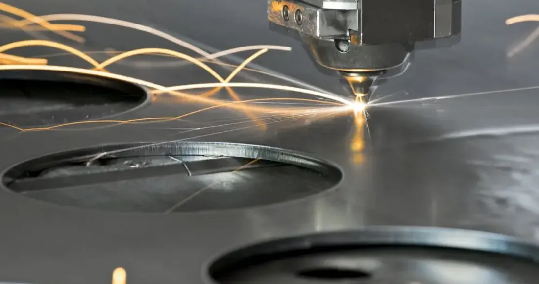
- Découpe laser
- Découpe au plasma
- Découpe au jet d'eau
2 - Bending
The bending process simply applies a great force on the sheet metal at a specific point to obtain the required shape. In some cases, the area under the bend might need some preparation. For instance, bend notches not only show the technician the location of the bend but can also facilitate the process itself.
3 - Stamping
To create a complex part in a limited time, manufacturers often select the stamping process, which is a complex form of form. The process uses a combination of different techniques using shearing, bending, and stretching to create new shapes out of sheet metal.
4 - Punching
To create a complex part in a limited time, manufacturers often select the stamping process, which is a complex form of form. The process uses a combination of different techniques including shearing, bending, and stretching to create new shapes out of sheet metal. Furthermore, some stamping processes even go as far as joining multiple pieces using different techniques as well.
Principaux avantages et limites de l'utilisation de la tôle pour la fabrication
Sheet metal parts designs are quite popular in many industries because of their perceived advantages. However, there are multiple limitations to the process as well. These advantages and limitations are among the most important design considerations for manufacturers as they determine the correct applications of the metal.
| Avantages | Inconvénients |
| Délais de production rapides comparés aux autres méthodes de fabrication. | Il est difficile de réaliser des motifs complexes avec des détails minutieux, ce qui peut limiter la gamme de formes et de modèles réalisables. |
| Pièces de haute qualité pour la production et le prototypage. | Nécessite des investissements importants en outillage et autres équipements, ce qui peut constituer un obstacle à la production à petite échelle. |
| Assez polyvalent pour travailler avec plusieurs métaux, tels que l'acier, l'aluminium et le cuivre. | Les délais de fabrication sont plus longs que pour les autres méthodes en raison des multiples étapes que comporte le processus, telles que la découpe, le formage et la finition. |
| Grâce à sa conception creuse, il offre un rapport résistance/poids élevé. | Cela nécessite une main-d'œuvre qualifiée, ce qui peut s'avérer coûteux. |
| Ne nécessite généralement aucun post-traitement. |
Directives pour la conception de la fabrication de tôles
As stated before, the design for sheet metal fabrication needs attention to some design requirements. Most of those requirements depend on the overall design of the product. For instance, a simple product would not have many requirements, but an intricate geometry would naturally need more processes to be market ready.
Sheet metal fabrication requires a series of best practices that can ensure perfection and deliver the best quality in the shortest time. The general guidelines for sheet metals include the following five categories.
Tolérances
Tolerance is one of the most important parameters for a variety of applications. The general rule of thumb states that more precision requires more resources and has additional costs. So, the tolerances should be according to the application.
The perfect example of this can be the automobile industry.
The precision required for the door, or any other part of the body would obviously be lower than the requirement for the chassis or some other integral part. Tolerance requirements depend on the project requirements, but that approach can have a lot of inconsistencies in the product.
Many manufacturers and industries prefer to set quality standards to avoid those inconsistencies. While these standards are not a one-size-fits-all solution, they are an excellent tool for maintaining consistency and performance. Furthermore, compliance with industry standards also makes it easier to fulfill industrial requirements and build consumers' trust in the brand.
For sheet metal fabrication, the prevalent standard is ISO 2768. This covers the tolerance requirements for multiple industries while maintaining the perfect balance between costs and processing capabilities.
Tolérances générales
For sheet metal fabrication, there are a few general tolerances that the industry uses everywhere. They are following international standards. However, there will be several exceptions to them in the case of sensitive applications like aerospace and automobile where precision is critical for performance.
| Fonctionnalité | Plage de tolérance prévalente | Notes complémentaires |
| Épaisseur de paroi | 0,9 mm à 20 mm | |
| Décalages | 0,3 mm à 0,7 mm | |
| Boucles | >2x material thickness | Toute dimension de courbure inférieure à celle recommandée rendrait la feuille cassante. |
| Courbes | 0.9mm – 1.2mm 1.8mm – 2.4mm 3.8mm – 5.0mm 7.5mm – 10mm 15mm – 20mm | Une tolérance de +/- degré est prévue sur tous les coudes. De plus, toute spécification supplémentaire entraînera des frais supplémentaires. |
| Ourlets | Inside die = material thickness with return length to be 4x the thickness | |
| Fraises à chanfreiner | Major die = +/- 0,254 mm Minor die > 2/3 thickness | |
| Trous et fentes | Dia > material thickness | Un diamètre inférieur à l'épaisseur du matériau provoquerait des fissures dans la tôle. |
| Encoches et languettes | Notch width > 1.5x thickness Length > 5x thickness |
Formation des bases
In this process, a flat sheet of metal is bent into a predetermined form by applying pressure. The process requirements and details change according to the type of bending process. While there are numerous ways, the following three methods of sheet metal bending are the most common.
· Brake pressing: The manual process uses a clamping bar and a plate to form the metal sheet. The process is only suitable for prototyping and small-scale productions.
· Roll bending: The same fundamentals, but the result would be in the form of cylinders, cones, or other arcs.
· Press brake bending: The most advanced bending process that uses hydraulic machines with a punch and dies. This is suitable for metal sheets up to the thickness of 6mm and can easily produce precise features.
Paramètres intégraux du pliage de tôles
When it comes to the bending process, there are multiple parameters that manufacturers and designers must consider. These design requirements are what fundamentally characterize any sheet metal bend, and it is advisable to adhere to their standards to ensure excellent results.
Voici les six paramètres les plus importants pour les opérations de pliage de tôle :
· Bend Line: The bend line is a straight line on the sheet's surface that marks the beginning to the end on both sides of the bend. The industry standard for bend lines is to keep the distance of five times the sheet thickness between the inside edge and outside of the bend.
Le rayon de courbure correspond à la distance entre l'axe de pliage et la surface intérieure du matériau, entre deux lignes de pliage. Il est généralement conseillé d'utiliser un rayon de courbure au moins égal à l'épaisseur du matériau. Un rayon de courbure supérieur est même préférable, car un rayon inférieur à l'épaisseur du matériau peut réduire la capacité de charge de la pièce.
· Bend Angle: The angle created by the bend with the imaginary perpendicular line coming from the axis. Rather than a specific number, the industry practice for bend angles is to ensure that the flange length must be four times the thickness. It is also good practice to keep all bend angles the same.
· Neutral Axis: The neutral axis is the portion of a sheet that remains at its original length because it is neither stretched nor compressed. It is an independent parameter, and there is no legal limit or guideline for its location. However, the accuracy of other factors such as bend radius and angle play a crucial role in determining the performance of the final product. Therefore, the more precise these factors are, the better the product is likely to perform.
· The K-Factor: The K-factor of a material is a measure of its location, determined by dividing the distance between the material and its thickness (t) by its T. The K-factor is subject to a range of factors, including the material type, bending process, bend angle, and others. To ensure optimal results, the K-factor should fall within the range of 0.25 to 0.50. The K metric can be calculated by the formula K = T/t.
· Bend Allowance: To make accurate and consistent bent parts, it's important to carefully measure and account for the arc length and the distance between the neutral axis and the bend lines. You should also use accurate bend allowances that are appropriate for the material and thickness to bend, as well as the type of bending process being used (e.g., air bending, bottom bending, or coining).
Bases de la coupe
Another important process in sheet metal fabrication is cutting. In many cases, it is an easier alternative that delivers fast results with acceptable precision. During the design phase, sheet metal design guidelines focus on the following five parameters.
Sélection des matériaux
During the process, the material characteristics play a key role in determining the suitable process for the specific material. Consider the example of Aluminum and Steel to understand this better. Naturally, cutting Aluminum would be simpler than dealing with steel because of steel's relative strength and durability.
For material selection, the best practice is to consider manufacturability as well. For instance, if both steel and aluminum can sustain loads of a particular operation, it is not always smarter to go for the stronger alternative (steel) without considering the manufacturing capabilities.
Diamètre du trou
When designing a product that involves drilling holes in a sheet, it is important to consider the thickness of the sheet and the diameter of the hole. A general rule of thumb is to ensure the diameter of the hole is at least equal to the overall thickness of the sheet.
If the diameter of the hole is too small in comparison to the thickness of the sheet, it can result in the formation of cracks and brittle areas around the hole. These cracks can propagate over time and lead to durability issues that can negatively impact the overall performance of the product.
Therefore, it is important to make sure the diameter of the hole is appropriate for the thickness of the sheet in order to maintain the structural integrity and long-term durability of the product.
Durcissement localisé
When materials are cut, the process can generate significant amounts of heat, which can have an impact on their properties. Specifically, the region surrounding the cut may become overheated, leading to localized hardening. To prevent this problem, it is recommended to slow down the cutting speed overall and to use coolants to regulate the temperature in the affected area. By doing so, the risk of localized hardening can be minimized.
Distorsion
Distortion in sheet metal fabrication refers to the warping, bending, twisting, or buckling of the metal sheet during the manufacturing process. This issue can occur due to a variety of factors, such as changes in temperature, stress, or pressure during the fabrication process. Distortion can cause significant problems in the final product, such as dimensional inaccuracies, poor fitment, and reduced strength.
Kerf
The kerf is related to the width of the cutting tool used and the thickness of the material being cut. It represents the width of the material that is removed by the cutting tool, and it determines how much material is wasted in the cutting process.
For example, if a laser beam has a kerf of 0.1mm, and a cut is made through a sheet of metal that is 1mm thick, then the total width of material removed from the sheet will be 0.2mm (0.1mm from each side of the cut). The kerf width may vary depending on the type of cutting process, the type of material being cut, and the thickness of the material.
It is important to consider the kerf when designing parts for sheet metal fabrication, as it can affect the final dimensions of the part. If precise dimensions are required, then the designer should take the kerf into account and adjust the design accordingly. Additionally, the kerf can also impact the cost of the fabrication process, as more material may be wasted with a wider kerf.
Caractéristiques communes des pièces en tôle
The sheet metal design deals with multiple features that allow these parts to fulfill the requirements of the industry. Here are the six main common features that sheet metal parts will often have.
Core Fillets
Les congés d'angle sont des bords ou des coins arrondis sur les pièces de tôle, créés pour éviter les arêtes vives, qui peuvent être dangereuses et provoquer une concentration de contraintes dans le métal, entraînant une rupture.
Suggestions:
- Dimensions : La largeur du congé doit être au moins égale à l’épaisseur de la tôle. Autrement dit, un congé de 2 mm est nécessaire pour une tôle d’une épaisseur maximale de 2 mm.
- Symétrie : Les congés d’une pièce doivent être symétriques. Cela signifie que les congés des angles opposés doivent avoir la même dimension.
- Uniformité : Les congés doivent être de taille uniforme sur toute la pièce. Cela signifie que les congés situés à tous les angles doivent avoir la même taille.
- Positionnement : Les congés doivent être placés aux endroits où des concentrations de contraintes sont susceptibles de se produire, notamment aux endroits où la tôle est pliée ou lorsqu’il y a un changement de forme ou de direction.
- Rayon : Le rayon du congé doit être aussi grand que possible. Cela permet de répartir les contraintes plus uniformément et de réduire le risque de concentrations de contraintes.
- Conception : La conception de la pièce doit permettre d'ajouter facilement des congés sans compromettre son intégrité.
Côtes
Les reliefs sont des éléments généralement perpendiculaires à la surface de la pièce en tôle. Ils servent à renforcer et à rigidifier la pièce sans en augmenter sensiblement le poids.
Suggestions:
- Maintenez l'épaisseur de la nervure à pas plus de 60% de l'épaisseur de la tôle pour éviter de créer des concentrations de contraintes.
- Utilisez des congés pour adoucir la transition entre la nervure et le matériau environnant, ce qui contribuera à répartir les contraintes plus uniformément.
- Évitez de placer les nervures trop près les unes des autres ou trop près des coudes, car cela peut créer des points faibles dans le matériau.
- Envisagez l'utilisation de nervures coniques ou à hauteur variable pour répartir les contraintes plus uniformément.
Gaufrage
Les alvéoles sont souvent utilisées pour diverses raisons, notamment : améliorer la rigidité et la résistance d’une pièce en tôle en la renforçant ; créer une surface lisse et plane pour la fixation d’éléments de fixation ou d’autres composants ; ménager un dégagement pour d’autres pièces ou composants.
Suggestions:
- Limitez la profondeur du gaufrage à 50% maximum de l'épaisseur de la tôle pour éviter de créer des concentrations de contraintes.
- Utilisez des congés pour adoucir la transition entre le gaufrage et le matériau environnant, ce qui contribuera à répartir les contraintes plus uniformément.
- Évitez de placer les reliefs trop près les uns des autres ou trop près des plis, car cela peut créer des points faibles dans le matériau.
- Tenez compte de l'impact du gaufrage sur l'aspect général de la pièce et assurez-vous qu'il soit conforme aux exigences de marque ou de conception.
Boss rond
Un relief circulaire en tôlerie sert à renforcer et rigidifier une pièce. Il est généralement obtenu par poinçonnage ou formage d'une dépression circulaire dans la tôle, ce qui provoque un bombement du métal sur le pourtour de la dépression et forme ainsi un relief circulaire.
Suggestions:
- Choisissez la taille et l'emplacement appropriés : réfléchissez bien à l'emplacement et à la taille du bossage afin de vous assurer qu'il fournira le soutien et la résistance nécessaires sans interférer avec d'autres composants ni créer de difficultés de fabrication.
- Utilisez l'outillage approprié : la réalisation d'un bossage rond nécessite un outillage spécialisé, tel qu'un jeu de poinçons et de matrices ou un outil de formage. Il est important d'utiliser l'outillage adapté afin de garantir un formage correct du bossage et d'éviter d'endommager la tôle.
- Tenez compte de l'épaisseur du matériau : l'épaisseur de la tôle influe sur la taille et la forme du bossage rond réalisable. Les matériaux plus épais peuvent nécessiter des bossages plus grands ou plus profonds pour garantir la résistance et la rigidité nécessaires.
Caractéristique des fossettes
Les alvéoles sont souvent utilisées pour diverses raisons, notamment : améliorer la rigidité et la résistance d’une pièce en tôle en la renforçant ; créer une surface lisse et plane pour la fixation d’éléments de fixation ou d’autres composants ; ménager un dégagement pour d’autres pièces ou composants.
Suggestions:
- Réfléchissez attentivement à la taille et à l'emplacement de la cavité. Celle-ci doit être placée aux endroits où elle sera la plus bénéfique, et sa taille doit être adaptée à l'application.
- Des alvéoles trop grandes ou trop profondes peuvent fragiliser le matériau, tandis que des alvéoles trop petites ou trop peu profondes peuvent ne pas fournir un renforcement suffisant.
- Choisissez l'outil adapté. Il existe différents outils pour créer des creux, comme les poinçons, les matrices et les outils de formage. Le choix de l'outil dépendra de la taille et de la forme du creux, ainsi que du type de matériau utilisé.
- Consider the thickness and material of the sheet metal. Diverse types of sheet metal may require different techniques or tools for creating dimples, and thicker materials may require more force or a larger tool.
- Tenez compte des limitations et restrictions de conception. Les alvéoles peuvent être utiles, mais ne conviennent pas à toutes les applications. Assurez-vous que la conception prenne en compte les problèmes ou difficultés potentiels liés à leur ajout.
Fonction de persienne
Les persiennes ont pour principal objectif d'améliorer la circulation de l'air et la ventilation dans l'enceinte ou le panneau sur lequel elles sont installées. Elles peuvent être conçues pour répondre à un besoin précis, comme diriger l'air dans une direction particulière, réduire le bruit ou protéger contre la poussière, la saleté ou l'humidité.
Suggestions:
- Dimensions : La taille des persiennes doit être soigneusement choisie en fonction du débit d’air requis et de l’espace disponible pour l’installation. Des persiennes trop petites risquent de ne pas assurer une ventilation suffisante, tandis que des persiennes trop grandes peuvent compromettre la solidité du panneau.
- Orientation : L’orientation des persiennes doit être choisie en fonction de la direction du flux d’air et de l’emplacement de toute obstruction ou obstacle potentiel susceptible d’affecter ce flux.
- Forme : La forme des persiennes influe sur l’efficacité du système de ventilation. Des persiennes profilées et aérodynamiques améliorent le flux d’air et réduisent les turbulences.
- Matériau : Le matériau des persiennes doit être choisi en fonction de l’application prévue et des conditions environnementales auxquelles le panneau sera exposé. Par exemple, l’acier inoxydable ou l’aluminium seront plus adaptés aux applications extérieures où l’exposition aux intempéries est un facteur important.
- Méthode de fabrication : La méthode de fabrication utilisée pour créer les persiennes doit être choisie en fonction de la précision, de la régularité et de la rentabilité souhaitées du processus de fabrication.
KO au round
Les poinçons ronds permettent de créer des trous de différentes tailles, selon la taille du poinçon et de la matrice utilisés. Ils sont couramment utilisés en tôlerie pour des applications telles que les boîtes électriques, les systèmes de chauffage, ventilation et climatisation (CVC) et les boîtiers.
Suggestions:
- Choisissez la bonne taille : assurez-vous d’utiliser le poinçon et la matrice adaptés au diamètre du trou souhaité. Un poinçon et une matrice de taille incorrecte peuvent entraîner un trou trop petit ou trop grand.
- Utilisez le bon matériau : les outils de découpe ronds sont généralement conçus pour fonctionner avec des types spécifiques de tôle ; assurez-vous donc d’utiliser l’outil de découpe approprié au matériau que vous utilisez.
- Veillez à ce que le poinçon et la matrice soient toujours bien affûtés : avec le temps, ils peuvent s’émousser et se déformer, ce qui peut entraîner des trous de mauvaise qualité. Maintenez-les affûtés et en bon état pour un résultat optimal.
- Tenez compte de l'épaisseur du matériau : les emporte-pièces ronds sont plus adaptés aux matériaux fins. Si vous devez percer des trous dans une tôle plus épaisse, vous devrez peut-être utiliser un autre outil ou une autre technique.
- Attention aux bavures : l’utilisation de trous prédécoupés ronds peut entraîner la formation de bavures sur le pourtour. Veillez à les éliminer à l’aide d’un outil d’ébavurage ou de papier de verre pour une finition impeccable.
Épaisseur du matériau
The recommended thickness for sheet metal depends on the specific application and the material being used. Thicker metals provide greater strength and durability, while thinner metals are more flexible and lightweight. Common thicknesses for sheet metal range from 0.5 mm to 6 mm but can vary based on the material and intended use. Here is a chart showing the recommended material thickness for some common metals used in sheet metal fabrication.
| Métal | Jauge | Millimètres | Pouces |
| Acier/Acier inoxydable/Aluminium | 22 | 0.8 | 0.031 |
| Acier/Acier inoxydable/Aluminium | 20 | 1.0 | 0.039 |
| Acier/Acier inoxydable/Aluminium | 18 | 1.2 | 0.047 |
| Acier/Acier inoxydable/Aluminium | 16 | 1.6 | 0.063 |
| Acier/Acier inoxydable/Aluminium | 14 | 2.0 | 0.079 |
| Acier/Acier inoxydable/Aluminium | 12 | 2.5 | 0.098 |
| Acier/Acier inoxydable/Aluminium | 10 | 3.2 | 0.126 |
Ce tableau fournit des indications générales, et l'épaisseur de matériau appropriée pour une application donnée peut dépendre de facteurs supplémentaires.
Erreurs courantes de conception de tôlerie à éviter
Sheet metal fabrication is a complex process that involves designing, cutting, bending, and assembling sheet metal into a final product. However, even the most skilled designers can make mistakes that can lead to costly rework or scrapped parts. To avoid these costly errors, it is important to be aware of the most common design mistakes and take steps to avoid them.
Mistake 1: A CAD File with No Bends
One common mistake to avoid is providing a CAD file with no bends. A sheet metal part without bends cannot be fabricated as a single piece and may require additional parts and labor to join multiple pieces together. It is important to include bends in the design and specify the bend angles and radii to ensure the part can be manufactured correctly.
Mistake 2: Features Too Close to a Bend
Another similar mistake includes accidentally placing features such as holes, tabs, etc. too close to a bend. What happens if you keep the features too close? You will end up with a deformed metal part that just wastes your money and time. To avoid making this mistake, you can just implement the 4T rule in all your CAD designs. The 4T rule dictates that all features should be four times material thickness away from any bend line at least.
Erreur 3 : Rayon de courbure interne parfaitement perpendiculaire
It is always tempting to use perpendicular lines in your CAD design. However, the reality is a bit different. Bending sheet metal mostly results in a rounded tip that gives your bend a radius. Attempting to achieve a perfectly sharp corner can result in material deformation and cracking, which can compromise the integrity of the final product. To avoid this issue, it is recommended to specify a minimum bend radius appropriate for the material and thickness being used. This will allow for a smooth transition in the bend and prevent stress concentrations that could lead to failure.
For your ease, you can easily find the bend radius of your metal parts by measuring the bent area's length and dividing the answer by two. While you can easily use different radii for each bent part, it is far more cost effective to use the same radius for all bends.
Erreur n° 4 : Ne pas inclure les détails matériels dans le fichier CAO
It is always best to include as many details in your CAD file as possible, including specific hardware specifications, sizes, and locations. This will ensure a smoother fabrication process and a more accurate final product.
Imagine needing a specific clinching nut such as the CLS - 440 - 2 for assembling a model but this detail was not included in the CAD file. There is nothing else to do besides waiting for other individuals to arrange the required hardware. Obviously, this delay will increase the assembly time and cost.
Mistake 5: Choose an Unsuitable Finish
Finishing is usually the last and essential step of the manufacturing process. Most people mistake finishing for only having one function, which is to make your part look better.
The type of finishing you select can also play an important part in protecting metal components against rust or corrosion. While finishing that only focuses on the aesthetics of the metal part exists, other types of finishing are designed to increase the life span of your product through their protective characteristics.
Aesthetic finishing, such as powder coating, does offer some protection. However, several finishings such as Silk Screening are only useful to add text or images to the metal parts. Chemical Conversion Finishes have the opposite function.
These finishes alter the outermost layer of your product and work as a protective coating. Besides this, you also have the Chromate Conversion finishing that gives metal parts electrical connectivity. It also provides a primer layer for painting.
It is important to understand what finishing you should use and what you should avoid. The right finish depends entirely on the application of the metal part that you are designing.
Mistake 6: Select the Wrong Sheet of Metal
You must consider the application of the part you are designing from start to finish. For example, you cannot use unfinished steel in a marine and salty environment. Doing so will leave your metal parts vulnerable to rust and corrosion.
Instead, select the right sheet metal by focusing on the flowing factors. Questions like the following are extremely important.
- What is the daily expected wear?
- Is your metal part being used in an environment prone to corrosion and rust?
- How easily can sheet metal be manufactured?
- How important is the cosmetic appearance of your metal part?
- Does your part require conductivity?
- What mechanical properties do your metal parts need to have?
Answering these questions will allow you to understand what your technical requirements are and let you make an informed design.
Erreur n° 7 : Négliger la résistance des matériaux pour les profilés en U
U channels are an important part of any product design, and their strength mostly depends on the overall strength of the material. Neglecting to take the material strength into account can result in U channels that are too weak, leading to bending or breaking under stress. To avoid this mistake, it is essential to select the appropriate material and thickness for the U channel. Based on the expected load and to factor in any additional stresses, such as vibrations or impacts, that the channel may experience in use.
Erreur n° 8 : Concevoir des exigences de soudage irréalisables
No matter how simple a design is, there are high chances that it would require some welding or other mechanical joints. Some designers make the common mistake of overestimating the welding capabilities of the unit, which in turn increases the complexity and costs.
The best way forward to avoid such issues is to implement strict design for manufacturing (DFM) practices. This ensures that all features are according to the prevalent standards.
Types de tôles
The term sheet metal is used quite widely in the industry. However, the metal used is one of the following.
- Stainless Steel: This is the most common and famous option because of its versatility and durability. Stainless steel is the first choice for applications where a cost-effective, durable, and strong option is needed.
- Cold Rolled Steel: An excellent option for application where material strength is the primary concern for the designers.
- Pre-Plated Steel: Like regular steel but comes with a special coating to prevent corrosion.
- Aluminum: A lightweight and inert option that delivers an excellent strength-to-weight ratio.
- Copper: Copper is an expensive, yet effective material. It does not react under normal conditions and delivers long-lasting performance without any chemical or biological degradation.
- Brass: An alloy of copper and Zinc that is both corrosion-resistant and hard enough to absorb multiple impacts.
Finitions courantes pour les pièces en tôle
While sheet metal works well without any processing, some applications take exception to this rule. The following processes are some of the most common post-processing steps for sheet metal products.
- anodisation
- Brossage
- Polissage
- sablage aux microbilles
- revêtement en poudre
- Placage
- Passivation
- Revêtement chromé
- Finitions personnalisées sur demande
KRRASS: Your Trusted Partner for Metal Sheet Forming Equipment
The metal sheet forming process is a critical step in modern manufacturing, requiring precision, reliability, and advanced technology. At KRRASS, we specialize in providing innovative equipment designed to meet the evolving needs of the industry and ensure compliance with the highest industrial standards.
KRRASS offers a comprehensive range of solutions for metal sheet forming, including CNC press brakes, fiber laser cutting machines, and other advanced equipment. Whether you are a startup aiming to build your production capabilities or an established enterprise seeking to upgrade your manufacturing technology, we are here to support you.
Our team at KRRASS understands the importance of precision and efficiency in the production process. With advanced tools and years of experience, we provide tailored solutions to help optimize your operations. Our CNC press brakes are engineered to deliver high-precision bending for various materials, while our fiber laser cutting machines offer exceptional speed and accuracy for complex cutting tasks.
Beyond equipment, we are committed to offering outstanding after-sales support, including training, maintenance, and technical assistance, ensuring that your machines deliver consistent performance for years to come.
When you choose KRRASS, you can rely on us to provide top-quality products that help improve productivity, reduce costs, and enhance the overall quality of your production processes.
Contact us today to explore our wide range of metal sheet forming equipment and discover how we can empower your business with advanced manufacturing solutions. You will be amazed at what our equipment can do for your sheet metal fabrication projects! We are here to help you every step of the way and make your manufacturing dreams a reality. Let us work together and create something amazing!


